
Measuring and Test Circuit
Index 48
RF_FIELD_DETECTOR
Published:2009/7/10 3:34:00 Author:May
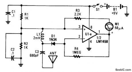
This detector is a half-wave rectifier for RF, which then feeds an op amp. U1A acts as an amplifier, driving meter M1. This circuit can detect mW RF levels from below the AM broadcast band to well above the FM broadcast band. (View)
View full Circuit Diagram | Comments | Reading(1749)
SSB_CW_PRODUCT_DETECTORS
Published:2009/7/10 3:33:00 Author:May
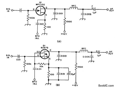
These circuits are used for product detection of single-sidebound (SSB) and CW signals. BFO injection is typically 0.5 to 1 V rms for both circuits. Frequencies can be up to 25 MHz or so. (View)
View full Circuit Diagram | Comments | Reading(1688)
PHOTO_EVENT_TIMER
Published:2009/7/10 3:32:00 Author:May
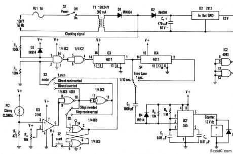
S2 is used to initiate timing. A light-to-dark or dark-to-light transition stops this timer,depending on the setting of S5. S3 offers a direct operating mode, rather than through the latch. IC3 and IC4 supply 0.1-or 1-second timing pulses. IC7 drives a time display counter, a 12-Vdc unit that draws less than 200 mA. (View)
View full Circuit Diagram | Comments | Reading(678)
UNDERVOLTAGE_DETECTOR
Published:2009/7/10 3:29:00 Author:May
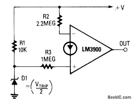
The output goes high when the supply falls below a value determined by zener diode D1. If D1 is a 5.6-V zener, the op amp will switch high when the supply voltage falls below approximately 11 V. The precise trip point can be varied by replacing R3 with an 820-kΩ resistor in series with a 470-k0 potentiometer. (View)
View full Circuit Diagram | Comments | Reading(853)
PEAK_DETECTOR
Published:2009/7/10 3:28:00 Author:May
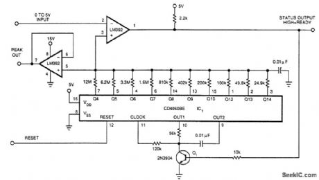
A 0-to-5 V input drives the negative input of LM392 comparator if reset (pin 12) if DC4060BE is pulled high then low, all outputs of ICF1 are forced low, forcing + input of comparator to go low. Q1 is cut off and 101's clock oscillator, running at about 775 Hz, starts counting. The Q4 through Q14 outputs con-nect to a ladder. When the counter reaches a count so that the voltage on pin 3 of the LM392 equals the peak input voltage, the counter stops. This voltage is available at the output of the voltage follower LM392 (pin 7). The maximum time to acquire a peak is 22 seconds. This circuit is slow and was originally intended for battery-charging applications. (View)
View full Circuit Diagram | Comments | Reading(0)
HALL_SENSOR_CURRENT_MONITOR
Published:2009/7/10 3:28:00 Author:May

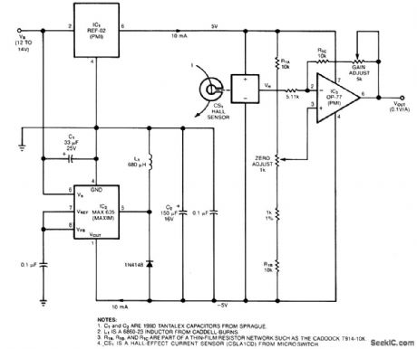
The circuit uses a Hall-effect sensor, which consists of an IC that resides in a small gap in a flux-collector toroid, to measure dc current from 1 to 40 A. Wrap the current-carrying wire through the toroid; the Hall voltage VH is then linearly proportional to the current (I). The current drain from VB is less than 30 mA.
To monitor an automobile alternator's output current, for example, connect the car's battery between the circuit's VB terminal and ground, and wrap one turn of wire through the toroid (or, you could wrap 10 turns-if they'd fit-to measure 1 A full-scale). When I=0V, the current sensor's (CS1's) VH output equals one-half of its 10-V bias voltage, VH and VOUT are zero when I is zero; you can then adjust the output gain and offset to scale VOUT at 1V per 10A (View)
View full Circuit Diagram | Comments | Reading(3610)
METAL_DETECTOR_1
Published:2009/7/10 3:26:00 Author:May
Using an oscillator running at 455 kHz, the metal-detector circuit produces an indication on the meter M1. When the oscillator frequency changes because of metal in the fteld of L1, the change will show as an increase or decrease in frequency, which produces a charge in the meter reading. The ceramic filter FILT1 produces a selective bandpass that yields this effect. L1 can be a 4 diameter coil wound on a suitable plastic form. About 10 turns of #26 wire are required. Use a frequency counter to adjust L1 and verify that Q1 is operating on or near 455 kHz. (View)
View full Circuit Diagram | Comments | Reading(0)
SCR_REPLACING_LATCHING_SWITCH
Published:2009/7/10 3:25:00 Author:May
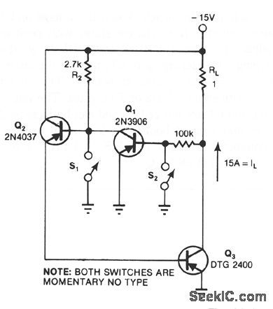
This circuit provides the turn-on characteristics of an SCR, but turns off with ease. The switch is comprised of three transistors with descending current ratings: Q3 has a high-current rating and Q2 has a medium rating. The current, I1, to be switched is 15 A. Momentarily depressing S2 removes Q1's base drive, turning Q1 off and allowing Q2 to turn on. Q2 then drives the base-emitter junction of Q3, turning Q3 on. Q3's collector-emitter voltage, which serves as Q1's base drive, is essentially zero, keeping Q1 off. To turn Q3 off, depress S1; this action momentarily shunts Q2's base current to ground, reversing the chain of events that turned Q3 on. (View)
View full Circuit Diagram | Comments | Reading(1025)
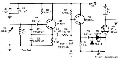
METAL_DETECTOR
Published:2009/7/10 3:24:00 Author:May
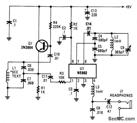
An NE602 acts as a heterodyne detector and Q1 as a sense oscillator. When L1 is brought near metal, it causes a charge in loop inductance, shifting the resonant frequency of L1 C6/C7. L1 is 5 turns #20 wire on a 9 diameter wood or plastic form. (View)
View full Circuit Diagram | Comments | Reading(0)
SWITCH_DEBOUNCER
Published:2009/7/10 3:23:00 Author:May
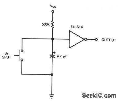
TTL inverter 74LS14 has an internal 16-KΩ,pull-up resistor that pulls the gate input high when the switch is open. As you close the switch, the 4.7-μF capacitor discharges on the ftrst contact. If the switch contacts bounce open, the internal resistor limits the capacitor's recharge to a rate sufficiently slow to prevent an undesired gate transition before the contacts again close. Note that the circuit correctly debounces the switch for both opening and closing. If you add an external pull-up resistor, you can use a CMOS Schmitt-trigger gate, 74HC14, and a smaller, 0.1-μF, capacitor. (View)
View full Circuit Diagram | Comments | Reading(2136)
FREQUENCY_METER
Published:2009/7/10 3:22:00 Author:May
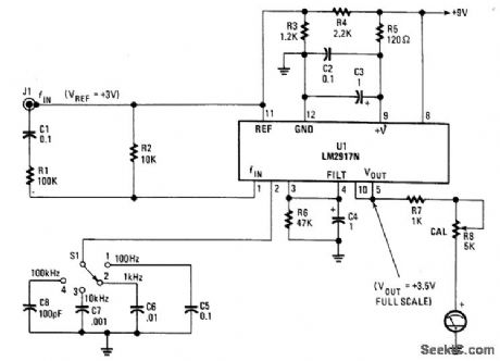
Using an LM2917N, this F/V converter-based circuit indicates the frequency on a meter. S1 selects full-scale range (up to 100 kHz). R8 is recommended to obtain the battery source. (View)
View full Circuit Diagram | Comments | Reading(4521)
TWO_SHEETS_DETECTOR
Published:2009/7/10 3:22:00 Author:May
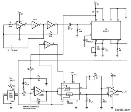
Using the principle of capacitance between two plat-es this circuit senses when more than one sheet of paper goes between the sensing electrodes ai a time. C1 is the, sensing capacitor formed of two plates. It consists of two plates 2 x15 with 0.1 spacing. A change, of capacitance causes a change in oscillator frequency of the IC1 circuit, which is detected by IC2 and IC3. (View)
View full Circuit Diagram | Comments | Reading(823)
THERMALLY_OPERATED_DIRECTION_DETECTOR
Published:2009/7/10 3:16:00 Author:May
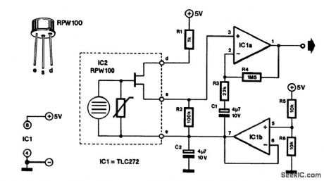
A heat-sensitive sensor can be used to construct a direction detector. Such a sensor reacts to all ani-mal heat. The one used in this design has a sensitive surface that has been divided into two. It, therefore, makes a difference, whether the heat approaches from the left or the right. The indication for cold objects is, of course, exactly the opposite.
Circuit IC1B forms a symmetric supply. Terminal s of the sensor is its output. The signal at s is ampli-fied in IC1A by a factor of about 70 before it is available at the output of the detector.
To obtain good directivity, it is best to place the sensor behind a single narrow slit, rather than behind the usual raster of a multifacetted mirror. The circuit draws a current of only a few mA from a 5-V supply. (View)
View full Circuit Diagram | Comments | Reading(1347)
SOUND_OPERATED_SWITCH
Published:2009/7/10 3:16:00 Author:May
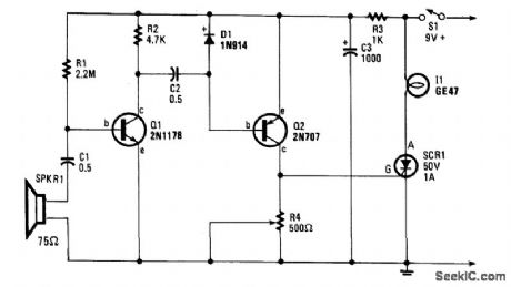
This sound-operated switch will sense the ring of the phone and translate this to a lamp that will go on and off. The amplified signal across R2 reaches D1 through capacitor C2. The rectified audio signals provide a negative bias for Q2, a pnp transistor. This causes Q2 to conduct so the current that triggers SCR1 is provided at the gate. Potentiometer R4 sets the sensitivity. R3 and C3 delay the operating voltage for Q1 so that the circuit will not be triggered on by the sound of the on/off switch, S1 or by the current surge.Set the lamp atop a TV receiver, turn it on and set the potentiometer so that a finger snap at two feet will trigger the lamp on. Place the speaker close to the telephone and give it a try. (View)
View full Circuit Diagram | Comments | Reading(673)
TRANSISTOR_TESTER
Published:2009/7/10 3:16:00 Author:May
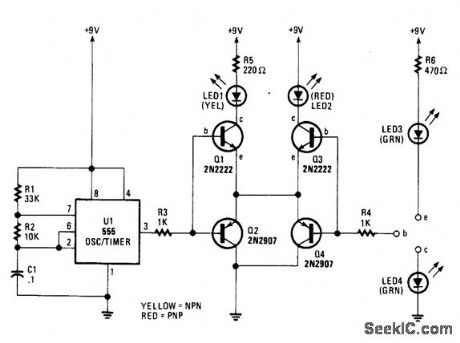
A 555 timer drives Q1 through Q4 with a square wave. LED1 and LED2 light when an npn or pnp transistor respectively, are connected to the text terminals. If LED3 and LED4 light equally as LED1 and LED2, the transistor is functional. If LED3 and LED4 are brighter than LED1 or LED2, the transistor is shorted. (View)
View full Circuit Diagram | Comments | Reading(3212)
PERMANENT_MAGNET_DETECTOR
Published:2009/7/10 3:14:00 Author:May
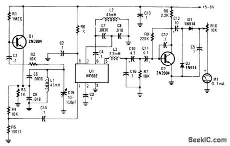
In this circuit, oscillator Q1 runs at about 15 kHz and feeds mixer U1. U1 has an internal oscillator that runs at around 15 kHz.C15 is used to zero-beat both oscillators. When a magnet is brought near L1 or L2, the magnetic field shifts the permeability of their respective cases. This changes the oscillator frequency, and the audio note is passed through ftlter L3, C16, and C10/R7 to amplifter Q2. There the audio is ampli-fied and drives meter M1 via rectiflers D1 and D2. (View)
View full Circuit Diagram | Comments | Reading(1022)
DIGITAL_TACHOMETER_COUNTER
Published:2009/7/10 3:02:00 Author:May
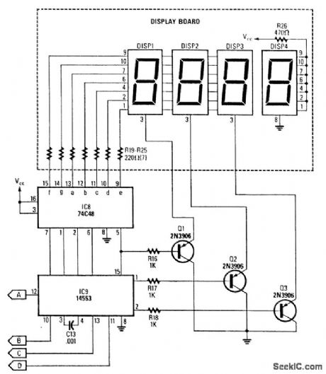
This circuit produces a readout for the digital tachometer circuit.IC9 is a 3-digit LED display driver,counter,and latch.IC8 drives the common-cathode LEDs,which are enabled by Q1,Q2,and Q3.See page 268,Fig.46-5 for the matching project. (View)
View full Circuit Diagram | Comments | Reading(10931)
DIGITAL_VOM_PHASE_METER
Published:2009/7/10 2:52:00 Author:May
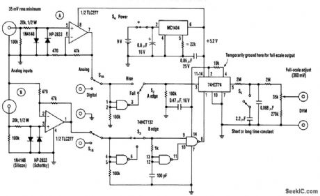
The phase-angle meter will work with either analog or digital inputs.A DVM is used as a readoutdevice.The output is 1mV per degree(360mV or degrees full-scale),The MC1404 precision regulator maintains calibration with a battery source(9V). (View)
View full Circuit Diagram | Comments | Reading(4344)
SIMPLE_DUTY_CYCLE_METER
Published:2009/7/10 2:41:00 Author:May
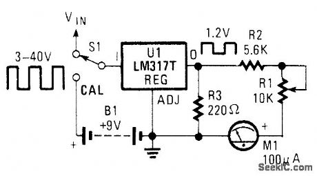
Using an LM317T as a precision clipper, this displays the duty cycle of a pulse train from 0 to 100% on a standard 100-mA analog panel meter. This circuit will work up to about 50 kHz. (View)
View full Circuit Diagram | Comments | Reading(2635)
MICROFARAD_COUNTER
Published:2009/7/10 2:39:00 Author:May
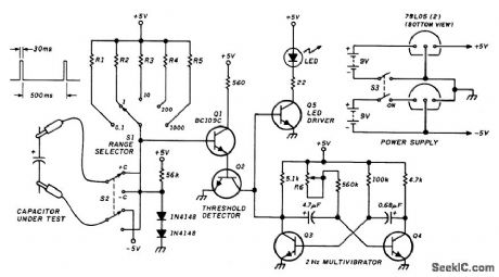
This circuit measures capacitance by the time it takes an unknown capacitor to reach 6.32 V (10V×63% or 1 RC time constant) when charged through resistor R. The LED used as a timebase is pulsed by Q3, Q4, and Q5. By counting seconds (two flashes per second) until threshold detector Q1/Q2 stops the count, you can directly read the number of microfarads. R1, R2, R3, R4, and R5 can be any convenient values, such as 1kΩ,10kΩ,100kΩ,1MΩ,10MΩ. (View)
View full Circuit Diagram | Comments | Reading(1119)
| Pages:48/101 At 204142434445464748495051525354555657585960Under 20 |
Circuit Categories
power supply circuit
Amplifier Circuit
Basic Circuit
LED and Light Circuit
Sensor Circuit
Signal Processing
Electrical Equipment Circuit
Control Circuit
Remote Control Circuit
A/D-D/A Converter Circuit
Audio Circuit
Measuring and Test Circuit
Communication Circuit
Computer-Related Circuit
555 Circuit
Automotive Circuit
Repairing Circuit