
Measuring and Test Circuit
Index 46
STEREO_AUDIO_POWER_METER
Published:2009/7/10 20:43:00 Author:May
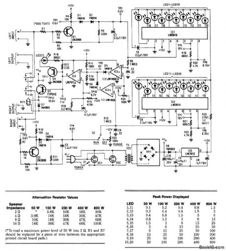
This circuit is used to meter the audio power output of an amplifier feeding a speaker. RY1 is actuated if excess power is fed to the speaker. Two channels are included for stereo applications. R1 and R2 and R3 form an attenuator. When a signal level is reached that produces a voltage across C1, comparator IC3A goes high, and IC4 and Q4produce enough drive to Q3 to trip relay 1, which cuts off the speakers. LED21 will light as well. In addition, IC1 reads the voltage across C1. IC1 is a bar-graph driver, which lights bar-graph display LED1 through LED10. (View)
View full Circuit Diagram | Comments | Reading(1126)
Decibel_measurement_circuit_using_an_AD536_true_RMS_to_DC_convener_chip_with_power_output_to_a_linear_meter_display
Published:2009/7/19 20:28:00 Author:Jessie
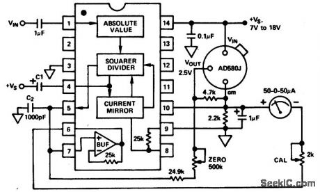
Decibel measurement circuit using an AD536 true RMS-to-DC convener chip with power output to a linear meter display (courtesy Analog Devices, Inc.). (View)
View full Circuit Diagram | Comments | Reading(2358)
SOUND_LEVEL_METER
Published:2009/7/10 20:35:00 Author:May
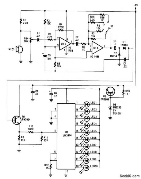
An electret microphone feeds an audio amplifier/rectifter combination. The amplifier has switchable gain. The rectifier output drives an LM3914 bar-graph generator. R14 provides fine gain control. (View)
View full Circuit Diagram | Comments | Reading(0)
DEVIATION_METER
Published:2009/7/10 20:32:00 Author:May
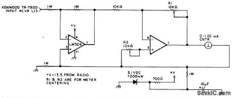
You can use this circuit in most FM VHF receivers; the hookup is off the FM discriminator.Because every signal transmitted has its own deviation signature,this can be a red plusin hunting jammers. (View)
View full Circuit Diagram | Comments | Reading(0)
1_MHz_bandpass_filter_insertion_loss_tester
Published:2009/7/17 5:24:00 Author:Jessie
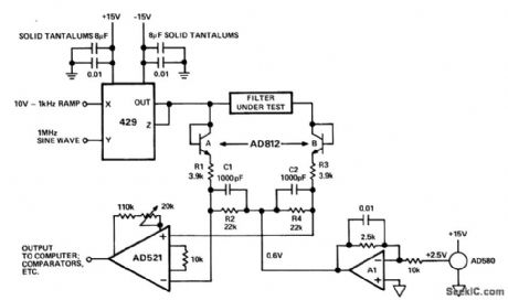
1 MHz bandpass filter insertion-loss tester. The test is performed by sweeping the amplitude of the input signal and comparing the envelopes of the input and output signals, The test signal is produced by modulating a 1 MHz sinusoidal carrier with a 10-volt 1 kHz ramp using a 429 multiplier. The test signal is demodulated by the diode-connected AD812A and network R1-R2-C1.The signal coming out of the filter under test is passed through an identical network consisting of AD812B, R3, R4 and C2. The AD521 compares the two demodulated outputs (courtesy Analog Devices, Inc.). (View)
View full Circuit Diagram | Comments | Reading(1027)
FREQUENCY_COUNTER
Published:2009/7/10 5:32:00 Author:May
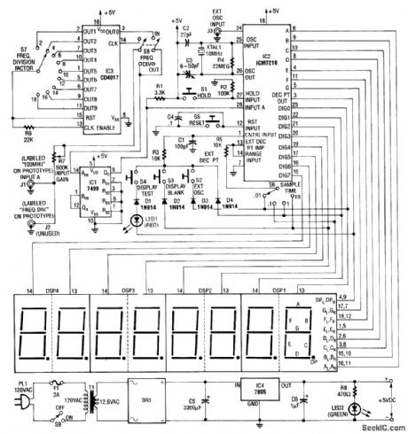
Built around an Intersil 7216 frequency-counter IC, this counter has a basic range of 10 MHz, a 100-MHz prescaler, and an extra frequency divider (IC3). This divider divides 'oy an extra factor, as marked on S7 (see schematic), to extend the range of the counten The display is multiplexed. MAN6710 2-digit red common anode 7-segment LED displays were used on the prototype. (View)
View full Circuit Diagram | Comments | Reading(0)
MODULATION_MONITOR
Published:2009/7/10 5:25:00 Author:May

Suitable for AM transmitters, this circuit uses neon lamps to indicate 50%, 85%, and 100% mod-ulation on negative peaks. (View)
View full Circuit Diagram | Comments | Reading(0)
BANDSWITCHED_GRID_DIP_METER
Published:2009/7/10 5:20:00 Author:May

For checking resonances,tuned circuits,antennas,etc.this circuit covers the 2-to 20-MHz range.Q1 serves as an oscillator tunable over this range vta C1 and bandswitched coils L1 through L8.When theprobe is coupled to a circuit resonant at the oscillation frequency,some RF power will be absorbed andtheoscillator output will drop,Q2,D2,D3,and Q3 form an RE detector and dc amplifier to drive meter M1,which will show the drop in Rf level,indicating resonance.R2 is a sensitivity control. (View)
View full Circuit Diagram | Comments | Reading(1297)
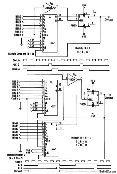
1__GHz_DIVIDE_BY_N_COUNTER
Published:2009/7/10 5:08:00 Author:May
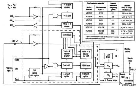
Counter speeds for CMOS- and TTL-programmable counters are limited to under 100 MHz. ECLtype devices can approach a few hundred MHz, but with significant current requirements. However, coupling the dual-modulus-prescaling technique with the available phase-locked-loop synthesizer chips that control the prescaler circumvents these frequency and power-drain constraints.
With this approach, designers can also choose various counter-programming schemes (serial, parallel, or data bus), in addition to achieving higher frequency capabilities. Low-power drain (less than 75 mW) and low-cost devices can also be selected. Moreover, only two ICs are necessary to achieve divide values above 131000.
Maximum input frequency and dividing range for the counter are controlled by choosing an appropriate 8-pin dual-modulus prescaler. The counter's output appears at synthesizer pin FV (see the figure). The total input-to-output divide value is governed by the equation:
NTOTAL=NxP+A
N and A represent the value programmed through the serial port into the divide-by-JV and divide-by-A counters. P is the lower dual-modulus value that is established by the synthesizer's modulus-control signal.
Typically, A varies from zero to P-1 to achieve steps within the system's divide range. N must be equal to or greater than A. N>A then sets a lower limit on jVTOTAL, which is dictated by AMAX=P-1. (View)
View full Circuit Diagram | Comments | Reading(1113)
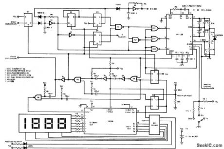
31_2_digit_DVM_using_an_IC_dual_ramp_system
Published:2009/7/19 20:59:00 Author:Jessie
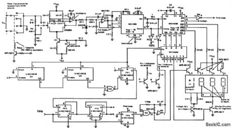
31/2-digit DVM using an IC dual-ramp system. Three input ranges allow the DVM to measure DC voltages of 0 to 1.9999 volts, 0 to 19.99 volts and 0 to 199.9 volts(courtesy Motorola Semiconductor Products Inc.). (View)
View full Circuit Diagram | Comments | Reading(1591)
Five_digit_accumulator_elapsed_time_and_indicator
Published:2009/7/19 20:56:00 Author:Jessie
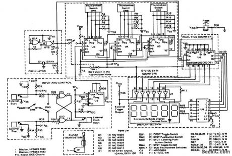
Five-digit accumulator/elapsed time and indicator. The elapsed time indicator has a maximum event of 9999.9 seconds. The accumulator has a maximum count of 99.999 times N, where N is a prescaler number from 1 to 999 (courtesy Motorola Semiconductor Products Inc.). (View)
View full Circuit Diagram | Comments | Reading(1771)
31_2_digit_autoranging_multimeter_using_an_MC14433
Published:2009/7/19 20:54:00 Author:Jessie
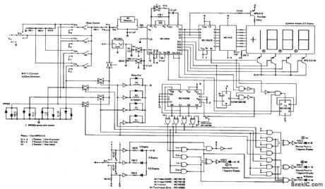
31/2-digit autoranging multimeter using an MC14433. The multimeter includes ranges from 200 millivolts 200 volts, AC and DC ampere ranaes from 2 milliamperes to 2 amperes full scale and resistance ranges from 2k to 2M full scale(courtesy Motorola semiconductor Products Inc.). (View)
View full Circuit Diagram | Comments | Reading(4312)
2_1_2_diigit_DVM_using_a_binary_D_A_convener_to_accomplish_conversion_of_the_BCD_input_signal
Published:2009/7/19 20:51:00 Author:Jessie
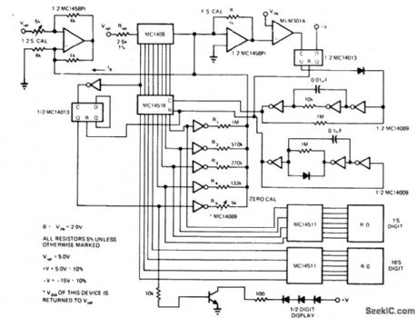
21/2-diigit DVM using a binary D/A convener to accomplish conversion of the BCD input signal (courtesy Motorola Semiconductor Products Inc.). (View)
View full Circuit Diagram | Comments | Reading(783)
Dual_polarity_3_1_2_digit_voltmeter
Published:2009/7/19 20:49:00 Author:Jessie
Dual-polarity 31/2-digit voltmeter. The complete circuit of nine packages and external components can be built on a 3- by 5-inch circuit board (coudesy National Semiconductor Corporation). (View)
View full Circuit Diagram | Comments | Reading(913)
Five_in_one_op_amp_specs_test_circuit
Published:2009/7/19 20:47:00 Author:Jessie
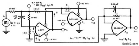
Five-in-one op amp specs test circuit. Tests can be made for open-loop gain, offset voltage, input bias current, quiescent current and output voltage swing (courtesy Burr-Brown Research Corporation). (View)
View full Circuit Diagram | Comments | Reading(717)
10_position_SCR_crowbar_life_test_fixture
Published:2009/7/19 20:37:00 Author:Jessie
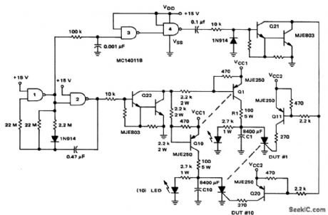
10-position SCR crowbar life test fixture (courtesy Motorola Semiconductor Products Inc.). (View)
View full Circuit Diagram | Comments | Reading(1107)
DIVIDE_BY_ODD_NUMBER_COUNTER
Published:2009/7/10 4:55:00 Author:May
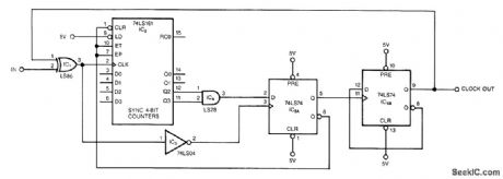
This circuit symmetrically divides an input by virtually any odd number. The circuit contains n+l/2 clocks twice to achieve the desired divisor. By selecting the proper n, which is the decoded output of the 74LS161 counter, you can obtain diisors from 3 to 31. This circuit divides by 25; you can obtain higher divisors by cascading additional LS161 counters.
The counter and IC5A form the n+l/2 counter. Once the counter reaches the decoded counts, n, IC5A ticks off an additional 1/2 clock, which clears the counter and puts it in hold. Additionally, IC5A clocks IC5B, which changes the dock phasing through the X0R gate, IC1. The next edge of the input clocks IC5A, which reenables the counter to start counting for an additional n+l/2 cycles.
Although the circuit has been tested at 16 MHz, a worst-case timing analysis reveals that the maxi-mum input frequency is between 7 and 8 MHz. (View)
View full Circuit Diagram | Comments | Reading(2520)
TTL_SOA_test_circuit
Published:2009/7/19 20:35:00 Author:Jessie
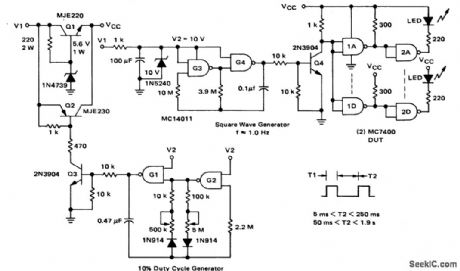
TTL SOA (safe operating area) test circuit (courtesy Motorola Semiconductor Products Inc.). (View)
View full Circuit Diagram | Comments | Reading(908)
CONTINUITY_TESTER_1
Published:2009/7/10 4:49:00 Author:May
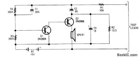
A continuity tester that has an audible indicator can be more useful in some cases than a visual indicator, because you need not take your eyes from the job at hand. Q1 and Q2 form an audio oscillator. When the test leads are connected to a continuous circuit, the oscillator operates, and sounds a tone from the speaker. (View)
View full Circuit Diagram | Comments | Reading(1885)
Buzz_box_continuity_and_coil_checker_using_an_LM3909_chip
Published:2009/7/19 20:24:00 Author:Jessie
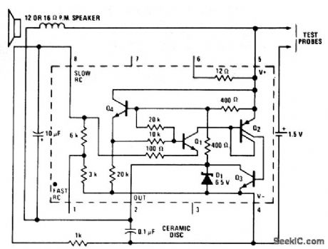
Buzz box continuity and coil checker using an LM3909 chip. Circuitry inside dashes is the LM3909. A short up to 100 ohms will cause a tone to be generated. By probing two values, such as a direct short and 5 ohms, a difference can be detected if done in quick succession (courtesy National Semiconductor Corporation). (View)
View full Circuit Diagram | Comments | Reading(832)
| Pages:46/101 At 204142434445464748495051525354555657585960Under 20 |
Circuit Categories
power supply circuit
Amplifier Circuit
Basic Circuit
LED and Light Circuit
Sensor Circuit
Signal Processing
Electrical Equipment Circuit
Control Circuit
Remote Control Circuit
A/D-D/A Converter Circuit
Audio Circuit
Measuring and Test Circuit
Communication Circuit
Computer-Related Circuit
555 Circuit
Automotive Circuit
Repairing Circuit