
Measuring and Test Circuit
Index 49
Continuity_and_coil_checker
Published:2009/7/19 22:57:00 Author:Jessie
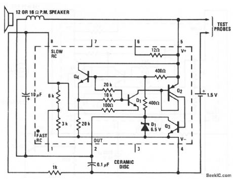
Using this circuit, a short (up to about 1000) across the test probes provides enough power to produce audible oscillation. In this circuit, the LM3909 is connected as an audio oscillator. By probing two values in quick succession, small differences (such as between a short and 5Ω) can be detected by differences in the tone. A novel use of this circuit is found in setting the timing of certain types of motorcycles. A different tone can be hoard if there is a short (or no short) in the low-resistance primary of the ignition coil (a difference between a 1 -Ω resistor and a 1 -Ω inductor can be detected). Quick checks of transformers and motors can also be made with this simple circuit. National Semiconductor Linear Applications Handbook, 1991, p 399 (View)
View full Circuit Diagram | Comments | Reading(724)
METER_TESTER
Published:2009/7/10 2:13:00 Author:May
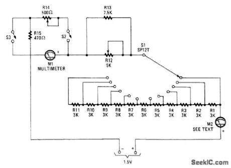
This unit uses switches and resistors to provide a number of current ranges. It allows you to test most of the meters available at surplus outlets, and without damaging the sensitive movements when you have no idea of internal resistance or full-scale current of the unit.
M1 is a multimeter set to measure current, and M2 is the meter-under-test. Starting with S1 set at the maximum resistance and S2 open, decrease the resistance setting of S1, fine tuning with R12, until M2 reads full scale. Then, read Ml. It will tell you the full-scale current for the unknown meter. As the meters are connected in series, the same current flows through both.
Now, close S2 and adjust R14 and R15 until M2 reads exactly mid-scale and M1 reads the same cur-rent as determined earlier to be the maximum current for M2. Half the current is flowing in M2 and half is going through R14 and R15. The voltage drop is the same across the meter and R14 and R15, because they're in parallel. Thus, the sum of the resistance of R14 and R15 is the same as the internal resistance of meter M2.
If the internal resistance of M2 is less than 470Ω, set R14 at maximum resistance and close S3. Read-just R14. Both R14 and R12 should be linear-taper potentiometers. (View)
View full Circuit Diagram | Comments | Reading(942)
SENSITIVE_SWR_METER
Published:2009/7/10 2:09:00 Author:May
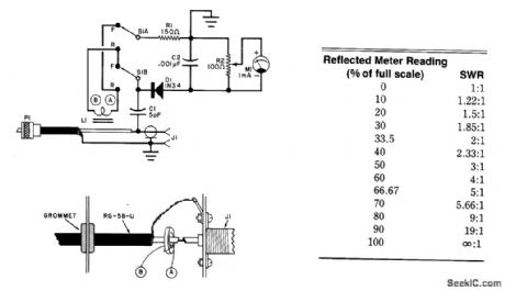
Using a toroidal pickup coil around the center conductor of a coaxial cable,this circuit can be used tomeasure the SWR of an antenna.L1 is two turns ﹟26 enameled wlre on a Fair-Rite 5963000301 toroidalcore. (View)
View full Circuit Diagram | Comments | Reading(3435)
LIGHT_DETECTOR
Published:2009/7/10 2:06:00 Author:May

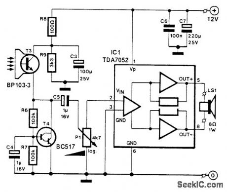
T3 is a photocell or phototransistor. T4controls the emitter voltage of T3. IC1 is an audio amplifier to provide amplification of the signal from the photocell. (View)
View full Circuit Diagram | Comments | Reading(789)
MAGNETIC_FIELD_METER
Published:2009/7/10 1:56:00 Author:May
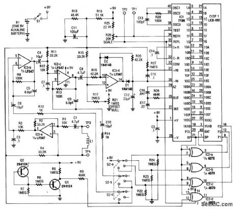
Using a pickup coil to drive an amplifier (IC3A-B-C-D), this meter circuit can be directly calibrated in field-intensity units. R3/C3 and R12/C7 establish a frequency roll off that compensates for the pickup-coil sensitivity, and set a 20-kHz cut-off point. S2 is the range-select switch. L1 is an 18-turn 3 diameter coil.The frequency range is 50 Hz to 20 kHz and the range of measurement is 0.1 to 20000 microlbsiers (μT). (View)
View full Circuit Diagram | Comments | Reading(1182)
SIMPLE_CAPACITOR_TESTER
Published:2009/7/10 1:51:00 Author:May
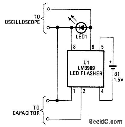
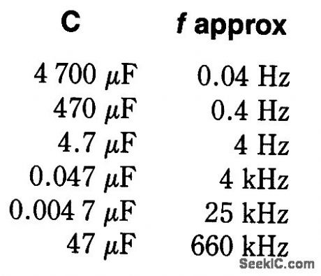
An LM3909 LED flasher is used as an oscillator,and the capacitor connected to the terminals determines frequency.
The LED can be used to count frequency visuallyusmg a stopwatch for large capacitors(C>500μF). (View)
View full Circuit Diagram | Comments | Reading(1413)
SIGNAL_DROPOUT_DETECTOR
Published:2009/7/10 1:28:00 Author:May
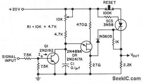
Used to Provide indiration of momentary dropout of d-c,a-c,or pulse input signal.lime between disappear of signal and indication of fault is adiustable. Outpul signal remains until scs is tumed off by momentarily opening reset switch.- Transistor Manual, Seventh Edition, Genercd Electric Co., 1964, p 336. (View)
View full Circuit Diagram | Comments | Reading(699)
SIMPLE_WINDOW_DETECTOR
Published:2009/7/10 0:57:00 Author:May
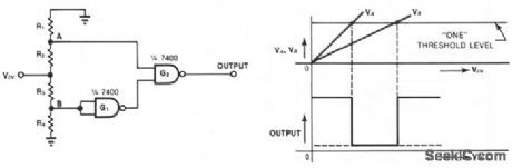
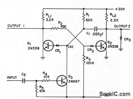
This simple window detector uses only half of a 7400 quad NAND gate plus four resistors, chosen so that the voltage at point A exceeds the voltage at point B for any input voltage. With no input applied or when VIN is at ground, the output of gate G1 is one; hence G2's output is also one. As the input voltage increases, VA, rises faster than VB. When VA reaches an acceptable one level, the circuit's output drops to zero. As the input continues to increase, VB rises to an acceptable level, changing the output of G2 to one. (View)
View full Circuit Diagram | Comments | Reading(857)
WINDOW_DETECTOR_3
Published:2009/7/10 0:54:00 Author:May
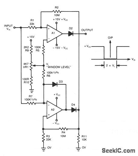
This novel window detector uses only two op amps。The width of the window can be changed by the 4.7-KΩ potentiometer. (View)
View full Circuit Diagram | Comments | Reading(725)
WINDOW_DETECTOR_2
Published:2009/7/10 0:49:00 Author:May
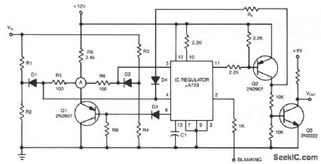
The detector circuit compares the output voltage of two separate voltage dividers with a fixed reference voltage. The resultant absolute error signal is amplified and converted to a logic signal that is TTL compatible. (View)
View full Circuit Diagram | Comments | Reading(692)
WINDOW_DETECTOR_1
Published:2009/7/10 0:47:00 Author:May

View full Circuit Diagram | Comments | Reading(0)
WINDOW_DETECTOR
Published:2009/7/10 0:46:00 Author:May
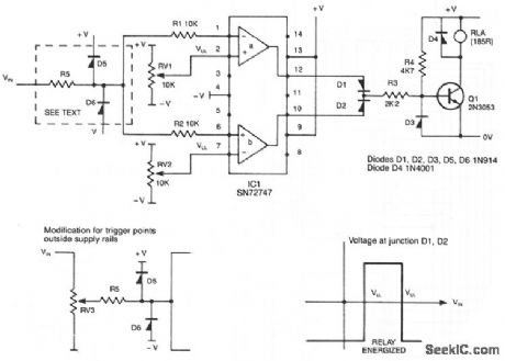
This circuit de-energizes a normally energized relay if the input voltage goes above or below two individually set voltages. The transistor driving the relay is normally turned on by R4, so the relay is normally energized. If the cathode of D1 or D2 is taken negative, Q1 will turn off and the relay will de-energize. The IC is a 72747 dual op amp used without feedback, so the full gain of about 100dB is available. The amplifier output will thus swing from full positive to fullmegative for a few mV change at the input. The relay is therefore only energized if VIN is between VUL and VLL. The two limits can be set anywhere between the supply rails, but obviously VUL must be more positive than VLL. If VIN can go outside the supply rails, D5, D6, and R5 should be added to prevent damage to IC1. If VUL and VLL are required to be outside the supply rails, VIN can be reduced by RV3. The supplies can be any value, providing that the voltage across them is not more than 30 V. (View)
View full Circuit Diagram | Comments | Reading(0)
LIGHI_DETECTOR
Published:2009/7/9 23:50:00 Author:May
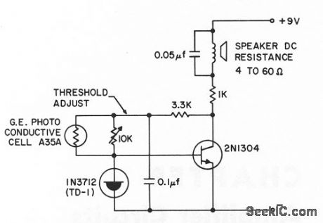
Gives 1,800-cps alarm tone when illumination on photocell exceeds predetermined level, which can be below 0.1 foot-candle near 5,500 angstroms.- Transistor Manual, Seventh Edition, Gemeral Electric Co., 1964, p 363. (View)
View full Circuit Diagram | Comments | Reading(762)
MISSING_PULSE_DETECTOR
Published:2009/7/9 23:44:00 Author:May
Warning light comes on to indicate occasional skipping of timing pulse or gate trigger having 20-pps rote, with durations ranging from 2 microsec to 30 millisec. Detector is triggered if interval between any two pulses exceeds 75 millisec, and must then be reset by pushbutton.-H.S. Reichard, Missing Pulse Detector, EEE, 10:6, p 35. (View)
View full Circuit Diagram | Comments | Reading(0)
PULSE_AND_D_C_MONITOR
Published:2009/7/9 23:42:00 Author:May
Indicates presence of continuous train of pulses, absence of one or more pulses in train, and dropout of d-c level beyond predetermined time interval. Uses controlled monostable mvbr. With d-c inputs, C2 is shorted. With values shown for R1 and C1, output occurs 1.07 millisec after last pulse.-Pulse and DC Monitor Circuit, Electronic Circuit Design Handbook, Mactier Pub. Corp., N.Y., p 201. (View)
View full Circuit Diagram | Comments | Reading(737)
200_MC_R_F_RADIATION_DETECTOR
Published:2009/7/9 23:41:00 Author:May
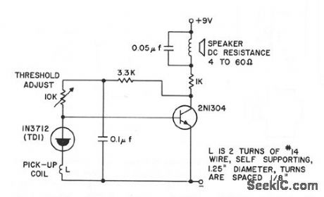
Gives 1,800-cps alarm tone when signal is picked up by coil or by small slot antenna serving as sensor.- Transislo r Manual, Seventh Edition, General Electric Co., 1964, p 363. (View)
View full Circuit Diagram | Comments | Reading(903)
EXPANDED_SCALE_ANALOG_METER
Published:2009/7/9 23:38:00 Author:May
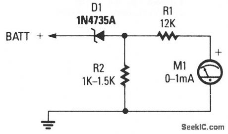
The circuit consists of 0-1 mA meter M1, 6.2-V zener diode D1, and 12-KΩ, 1% resistor R1. R2 is included in the circuit as a load resistor for the zener diode. The value of R2 isn't critical; use a value of 1000 to 1500 Ω. The meter reads from 6 to 18 volts, which is perfect for checking a car's charging system. (View)
View full Circuit Diagram | Comments | Reading(949)
SIMPLE_AUDIO_CLIPPER_LIMITER
Published:2009/7/9 23:37:00 Author:May
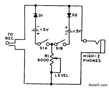
For use with headphones, this circuit sets the audio clipping level via a 5-KΩ pot. This type of noise clipper works best for pulse-type noise of low duty cycle, such as ignition noise. R1 sets the bias on the diodes for the desired limiting level. (View)
View full Circuit Diagram | Comments | Reading(2515)
TRANSIENT_PULSE_DETECTOR
Published:2009/7/9 23:28:00 Author:May
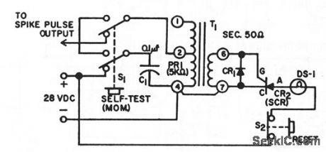
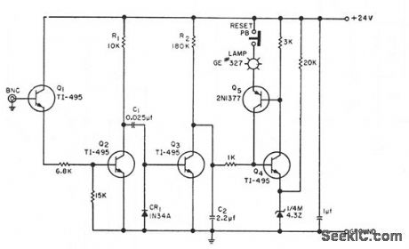
Delermines occurrence of single spike pulse hoving moximum amplitude of 50 v at 2 ma and durotion of 1 millisec. Spike pulse is stepped down by transformer to 5 v at 20 ma, which is sufficident to fire GE C10 scr, causing 28-v lamp to come on. When reset button is pressed, str cuts off, lump goes out, and circuit is ready for another spike. C1 is 0.1 mid and CR1 is IN270.-Transient Spike Pulse Detector, Electronic Circuit Design Handbook, Mactier Pub. Corp., N.Y., p 204. (View)
View full Circuit Diagram | Comments | Reading(971)
WIDE_RANGE_AC_VOLTMETER
Published:2009/7/9 23:24:00 Author:May
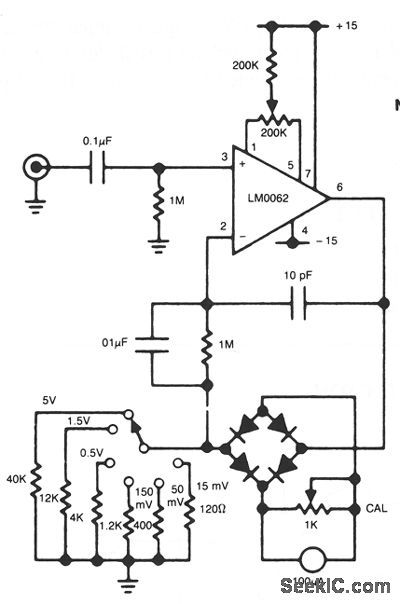
In this circuit, a diode bridge is used as a meter rectifier. The offset voltage is compensated for by the op amp, since the bridge is in the feedback network. (View)
View full Circuit Diagram | Comments | Reading(938)
| Pages:49/101 At 204142434445464748495051525354555657585960Under 20 |
Circuit Categories
power supply circuit
Amplifier Circuit
Basic Circuit
LED and Light Circuit
Sensor Circuit
Signal Processing
Electrical Equipment Circuit
Control Circuit
Remote Control Circuit
A/D-D/A Converter Circuit
Audio Circuit
Measuring and Test Circuit
Communication Circuit
Computer-Related Circuit
555 Circuit
Automotive Circuit
Repairing Circuit