
Measuring and Test Circuit
Index 40
SEQUENTIAL_TIMER
Published:2009/7/12 21:57:00 Author:May
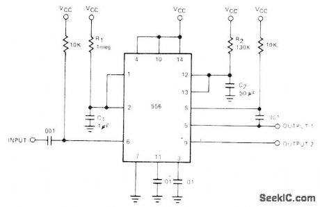
Output offirst ham of 556 dual timeris fed to input of second half through 0.001-μF coupling capacitor to give total delayequal to sum of individual timer delays,First half of timer is started by connecting pln 6 momentarily to ground After interval determinedby 1.1R1C1,second timer starts its delay determinod by 1.1R2C2- Signetics Analog Data Manual, Signetits、Sunnyvale,CA,1977,p724. (View)
View full Circuit Diagram | Comments | Reading(0)
STABLE_FOUR_TRANSISTOR_TIMER
Published:2009/7/12 21:56:00 Author:May
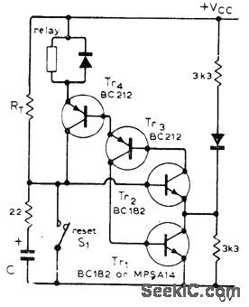
Circuit has good immunity to impulse noise because normal state of all transistors is on. This eliminates spurious timing cycles that sometimes occur in IC timers. At switch-on, C begins charging until its voltage makes Tr2 start conducting; this in turn makes other three transistors switch on. Regeneration action then discharges C to about 0.6 V. Timer is started either by applying VCC or opening S1. Timing period depends on value of VCC.-J. L. Linsley Hood, One-Shot Timer Circuit, Wireless World, Nov. 1975, p 520. (View)
View full Circuit Diagram | Comments | Reading(990)
SEQUENCED_TIMERS
Published:2009/7/12 21:54:00 Author:May
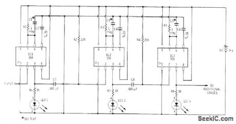
Cascading of three 555 timels, each driving LED, gives sequenced flashes with individually adjustable durations. Times of timers are determined by values used for C1, C3, and C5. R1, R3, and R5 values also affect time delays; use pots if 1 μF is used forall three capacitors.-F. M. Mints, Integrated Circult Projects, Vol. 5, Radio Shack, Fort Worth, TX, 1977, 2nd Ed., p 64-75. (View)
View full Circuit Diagram | Comments | Reading(1039)
PC_POWER_PINCHER
Published:2009/7/12 21:43:00 Author:May
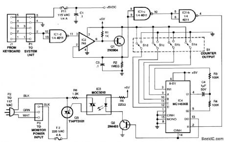
The figure is a diagram of the circuit, in which a low-frequency oscillator continually drives the input of a multistage binary counter. Whenever the count reaches the setting selected by DIP switch S1, the circuit turns triac Q3 off, thereby interrupting the flow of 120-Vac to the monitor. A keyboard-monitoring circuit keeps the video monitor powered up during active use by resetting the counter every time a key is pressed. As long as a keypress occurs before the time delay expires, the counter keeps resetting. Hence, it never times out, and the monitor continues to receive power. When the computer turns on, a routing in its basic input/output system (BIOS) polls the keyboard. The keyboard, in turn, sends a series of data pulses back to the microprocessor to indicate its status. The data line is normally high (+5 V), and the pulses are low-going transitions. The first stage of the power pincher inverts the sense of the logic to normally low with high-going transitions. (View)
View full Circuit Diagram | Comments | Reading(1253)
MINIMUM_DRAIN_TIMER
Published:2009/7/12 21:42:00 Author:May
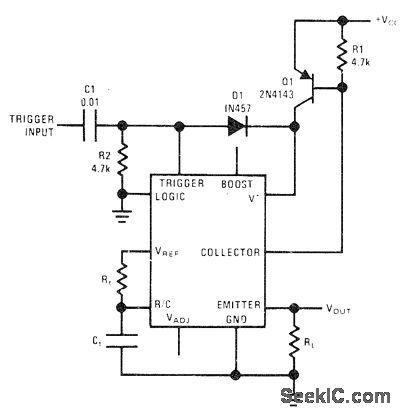
National LM122 timer is connected to reduce supply drain to zero between timing cycles. External PNP transistor Q1 serves as latch between V+ ternlinal of timer and power supply. Between timing periods, Q1 is off and no current is drawn. Arrival of 5-V or larger trigger pulse turns Q1 on forduration of timing period set by Rt and Ct, which can range from microseconds to hours. -C. Nelson, Versatile Timer Operates from Microseconds to Hours, National Semiconductor, Santa Clara, CA, 1973, AN-97, p 10. (View)
View full Circuit Diagram | Comments | Reading(823)
WINDOW_DETECTOR
Published:2009/7/12 21:41:00 Author:May
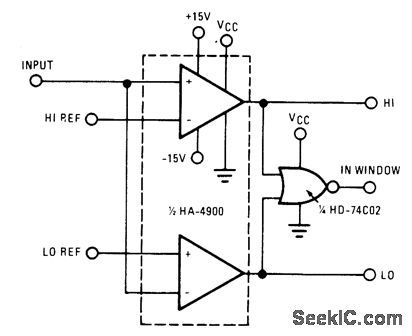
The high switching speed, low offset current and low offset voltage of the HA-4900 series make this window detector extremely well-suited for applications that require fast, accurate decision-making. This circuit is ideal for industrial-process system-feedback controllers, or out-of-limit alarm indicators. (View)
View full Circuit Diagram | Comments | Reading(0)
CASCADED_TIMER
Published:2009/7/12 21:34:00 Author:May
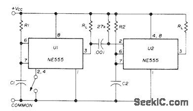
Two NE555 timers give sequential timing intervals for two separate loads.Time for U1 is set by R1 and C1, and for U2 by R2 and C2. Grounding pin 2 momentarily with switch starts timing. Once started, it cannot be retriggered. With pin 2 connected to reset input 4, both functions are obtained with one push of switch, lf reset function is not wanted, connect 4 to 8. When pin 3 of U1 goes low at end of timing interval, negative pulse generated by 0.001-μF capacitor and 27K resistor goes to pin 2 of U2 to trigger second timer. With 15-V supply, each timer can handle 200-mA load.-H. Vordenbaum, Automatic Reset Timer, Ham Radio, Oct. 1974, p 50-51. (View)
View full Circuit Diagram | Comments | Reading(1125)
FLASHING_LED_EGG_TIMER
Published:2009/7/12 21:10:00 Author:May
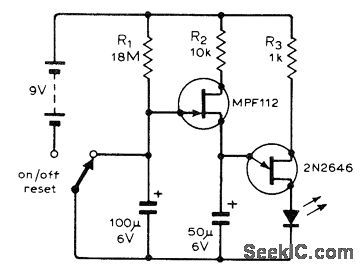
UJT oscillator controlled by FET timer makes LED flash after time delay determined by value of R1. When 100μF capacitor charges to about 1 V after switch is turned on, MPF112 FET switches on and forms part of charging circuit for 2N2646 UJT oscillator which then pulses LED at about 200 mA peak. Although developed as inexpensive egg timer, circuit has many other applications.-J. Jeffrey, Simple FlashingL.E.D. Timer, Wireless World, Oct. 1974, p 381. (View)
View full Circuit Diagram | Comments | Reading(2822)
PRESEITABLE_ANALOG_TIMER
Published:2009/7/12 21:09:00 Author:May
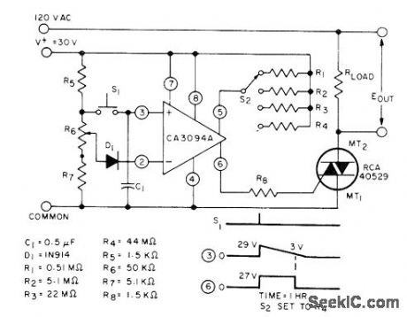
Switch S2 gives choice of four delay intervals between closing of S1 and triggering of triac by RCA CA3094A programmable power switch and amplifier,Pot R6 is required for initial time set. - Linear Integrated Circuns and MOS/FET's, RCA Solid State Division、Somerville,NJ,1977, p 192-196.
(View)
View full Circuit Diagram | Comments | Reading(860)
ULTRA_SIMPLE_RS232_TESTER
Published:2009/7/12 21:05:00 Author:May
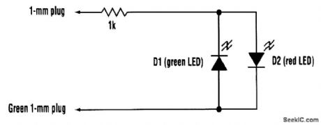
The tester consists of no more than a two-color LED (or a red and a green LED connected in anti-parallel) in series with a 1-kΩ resistor. The free ends of the resistor and the LEDs should preferably be terminated in 1-mm plugs. One of the free ends should be covered in green sleeving, or use a green 1-mm plug. This is touched on pin 7 (signal ground) of the connector under test. The other end is touched on each pin to be tested, in turn. The LED (or LED pair) is connected so that a positive voltage emits a red glow and a negative voltage causes a green glow. Sometimes, an RS232 input will be found that has an internally connected pull-up to drive a particular default RS232 level when unconnected. Although this will cause the tester to glow as if the pin were an output, it will do so with markedly less brightness. Bearing this in mind, the tester can be used to diagnose most RS232 problems at the electrical level. (View)
View full Circuit Diagram | Comments | Reading(3354)
PROPAGATION_TIME
Published:2009/7/17 2:43:00 Author:Jessie
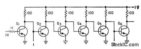
Inverter circuit chain was developed to measure propagation time of 2N834 epitaxial mesa transistors. Pulse is applied to input, and outputs at 1 and 2 compared to get shift for four stages. Typi-cal time measured was 4 nsec per stage.-W. D. Roehr, Epitaxial Process Improves Transistor Characteristics, Electronics, 34:9, p 52-53. (View)
View full Circuit Diagram | Comments | Reading(900)
PORTABLE_COATING_THICKNESS_GAGE
Published:2009/7/17 2:42:00 Author:Jessie
Uses magnetic saturation to measure thickness of up to 0.020-inch paramgnetic coating on nonmagnetic base. Weight is 40 lb, and accuracy 5%.-P. Dick, Measuring Thickness of Paramagnetic coatings, Electronics, 34:8,p 48-50. (View)
View full Circuit Diagram | Comments | Reading(889)
LIQUID_LEVEL
Published:2009/7/17 2:31:00 Author:Jessie
Nonconducting liquids change electrostatic capacitance of ring electrodes in tank. Amplified error signal from electrode bridge operates recording galvanometer or indicator lamps to provide measurements of level accurate to 0.01 inch.-T. L. Greenwood, Capacitance Change Indicates liquid Levels, Electronics, 33;34, p 66-67..
(View)
View full Circuit Diagram | Comments | Reading(879)
TRANSISTOR_TESTER_2
Published:2009/7/12 20:28:00 Author:May
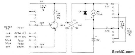
Useful for troub:eshooting and forchecking small-slgnal transistors having no markings Set four-pole five-position rotary switch S2 to SHORT(lowestpostion) before inserting transistor,then flip S1 back and forth,If meter shows any reading at all,reject transistor without further tests,rmeter stays at zero,set S2 to ICBO(conector-base current, emitter open). Discard transistor if reading is high foreither position of S1; modern transistors pass only nanoamperes, but older types may give noticeable reading, particularly if germanium. Repeat test for ICEO (collector-emitter current, base qpen), which should be greater than ICBO by factor approximating curtent gain (beta) of device, Modern silicon transistors may give no reading here. For final beta test, older types show 100 or less and modern transistors like 2N3391 have beta readings between 300 and 400. CR1 is 1N4603.-D. Cheney, Shirt Pocket Transistor Tester, Ham Radio, July 1976, p 40-42. (View)
View full Circuit Diagram | Comments | Reading(1324)
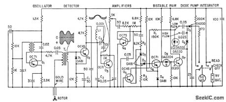
WIRE_THICKNESS_GAGE
Published:2009/7/17 2:29:00 Author:Jessie
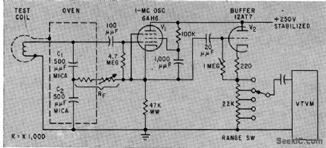
Uses principle of proximity detectors for nondestructive measurement of moving copper wire thickness during drawing operation or on coil-winding machine. Wire passing through test coilacts like shorted turn of transformer, lowering Q of coil. Stable 1-Mc oscillator and buffer drive vtvm that indicates variations in wire diameter for sizes down to AWG 46. -K. H. Jaensch, Wire Gage Provides Continuous Measurement, Electronics, 33;7, p 109-111. (View)
View full Circuit Diagram | Comments | Reading(1352)
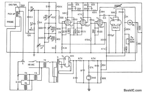
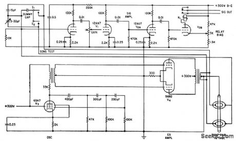
POPCORN_NOlSE_TESTER
Published:2009/7/11 5:27:00 Author:May
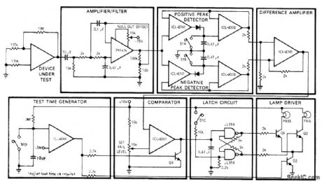
Developed at Intersil to test opamps for erratic low-frequency jumps between two or more stable states. After start-up switch S is closed, pass/fail lamps are inhibited by Q3. At end of preselected test time (typically 5 s), one of lamps will come on. If output from difference amplifier exceeds preset fail level at inverting input of comparator during test period, fail lamp is turned on by Q2. Q4 prevents triggering of latch by spurious signals after end of test time.-T. P. Rigoli, IC Op Amps, EDNMagazine, May 1, 1971, p 23-33. (View)
View full Circuit Diagram | Comments | Reading(949)
VOLTAGE_LEVEL_MONITOR
Published:2009/7/11 5:26:00 Author:May
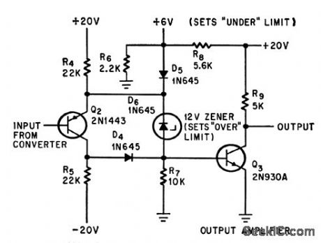
Over-or-under circuit provides output signal when d-c input voltage is over 12V or under 6v, for monitoring or alarm purposes, with no output during desired on condilion.-M. Merlen and D.Grossman, Interrogator Circuit Can Tell Good Data from Bad, Electronics, 37:20, p58-59. (View)
View full Circuit Diagram | Comments | Reading(1028)
IN_CIRCUIT_TESTER
Published:2009/7/11 5:25:00 Author:May
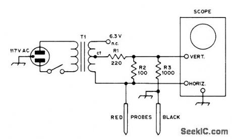
Eliminates need for removing components one by one for testing. Voltages and currents used are low enough for almost any transistorized circuit. Will test for shorts and opens. Shows folward-reverse ratios on junction transistors and diodes. Lissajous figures and other combination displays on CRO facilitate analysis of circuits having reactive components, transistors, and ICs. Will detect high-resistance solder joint and check continuity of switches, fuses, lamps, and printed wiring. Displays form hands of clock or ovals. Vertical line indicates short, horizontal means open, slant indicates resistance, vertical oval is inductance, horizontal oval ii capacitance, diode and highest-merit transistor show 3 o'clock, fair transistorshows 4 o'clock, and poor transistor shows 5 o'clock. For other patterns, compare with those obtained with known good components.-D. L. Ludlow, The Octopus, QST, Jan. 1975, p 40-42. (View)
View full Circuit Diagram | Comments | Reading(3649)
5_DIGIT_PRESET_COUNTER
Published:2009/7/11 5:24:00 Author:May
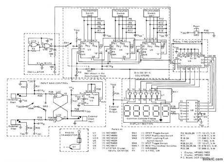
Basis of circuit is Motorola CMOS real-time MC14534 five-decade counter containing five ripple-type decade counters whose outputs are time-multiplexed by intemal scanner. Time-base oscillator pro-vides 10-kHz crystal reference for clocking counters. Total current drain of system is 65 mA from 5-V supply. When used to control quantity of items placed in carton, each item interrupts light beam of photoelectric system to give count. External trigger output is connected to control mechanism that advances conveyor belt when box is full. Quantity of items desired per box is dialed on thumbwheel switches. Dis-play is used to indicate number of boxes filled. Other applications include count and display of number of interruptions of light beam, mea-surement of conveyor speed, and measurement of log lengths in sawmilL-A. Mouton, Five Digit Accumulator/Elapsed Time Indicator, Motorola, Phoenix, AZ, 1975, AN-743 p 3. (View)
View full Circuit Diagram | Comments | Reading(3728)
TRANSISTOR_POWER_GAIN
Published:2009/7/17 2:26:00 Author:Jessie
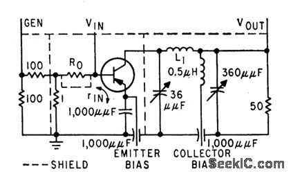
Measures power gain as a function of frequency. When maximum oscillation frequency is approached, unilateral gain drops at rate of 6 db per octave. Input generator has 1 ohm internal resistance. Pi network matches transistor output to load resistor.-J. Lindmayer and R. Zuleeg, Determining Transistor High-Frequency Limits, Electronics, 32;34, p 31-33. (View)
View full Circuit Diagram | Comments | Reading(966)
| Pages:40/101 At 202122232425262728293031323334353637383940Under 20 |
Circuit Categories
power supply circuit
Amplifier Circuit
Basic Circuit
LED and Light Circuit
Sensor Circuit
Signal Processing
Electrical Equipment Circuit
Control Circuit
Remote Control Circuit
A/D-D/A Converter Circuit
Audio Circuit
Measuring and Test Circuit
Communication Circuit
Computer-Related Circuit
555 Circuit
Automotive Circuit
Repairing Circuit