
Measuring and Test Circuit
Index 26
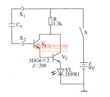
Measuring Triac circuit diagram with digital multimeter
Published:2011/9/7 21:38:00 Author:Lucas | Keyword: Measuring Triac , digital multimeter
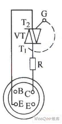
The chart shows the digital multimeter measuring circuit. When it is appropriated to NPN file, then the G base of Triac VT is open and connected to C hole of hFE socket by a current limiting resistor R (330Ω or so), T1 is inserted into the E hole by wires. Resistor R here is used to prevent hFE circuit overload, and at this time, digital multimeter display is 000 , that is the off stste, then the G pole and T2 are in short connection by wires, then digital multimeter jumps immediately to 578 , which explains that it had turned. The right figure is the Triac double passing validation circuit.
(View)
View full Circuit Diagram | Comments | Reading(1762)
ECG telemetering circuit diagram
Published:2011/9/7 2:43:00 Author:Lucas | Keyword: ECG telemetering
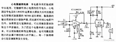
The circuit is designed for experimental or teaching, and it can be used to hear the ECG signal voltage. ECG signal voltage is amplified by the LM4250 op amp for modulating the NE566, which is connected as voltage-controlled oscillator, and oscillator output is used to drive small speakers, so you can hear the ECG signal. If you want to telemetry, you can use the microphone to pick up the sound output. In order to connect the circuit and the patient, you can use standard adhesive monitoring electrodes, you can also use a small piece of metal to tie to the patient's wrist by rubber.
(View)
View full Circuit Diagram | Comments | Reading(2048)
Mini rhythm tester circuit diagram
Published:2011/9/7 3:11:00 Author:Lucas | Keyword: Mini rhythm tester
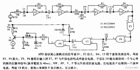
HTD receives heart beat signal, then it is amplified by F1, F2. R4, C3 are used to filter out high frequency signal, then it is input F7 afeter amplifing by F3, F4, shaping by F5, F6. F7 and the peripheral circuitform the monostable circuit, so it gets positive pulse signal with the frequency being the same with heart rate at the F8 output end ( pulse width is 40ms). DW, RP, V, P form the constant current circuit, and it will get a pulse current in P of the meter, then it is integrated by C8 to make the faster heart rate and greater P display. In the contrary, the rate and display is smaller.
(View)
View full Circuit Diagram | Comments | Reading(1222)
Pressure monitoring system composed of intelligent sensor signal processor MAX1460 and silicon pressure sensor
Published:2011/9/7 2:50:00 Author:Lucas | Keyword: Pressure monitoring system, intelligent sensor, signal processor , silicon pressure sensor
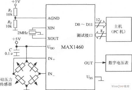
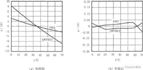
The system uses the +5 V supply, and the crystal frequency is 2MHz. R1 and R2 form the power divider, and the analog ground (AGND) is on the midpoint of the power supply. C is the power supply decoupling capacitor. Host can use PC, and the host firstly tests MAX1460 and receives 12-bit parallel data output by MAX1460, then it moves out the testing system, and MAX1460 and the sensor form a high-precision intelligent pressure monitoring system, and the conversion rate is 15 times / sec, the measurement error is less than ± 0.1%. In the Figure, the FSO is the full-scale, OFFSET is the disorder, γ indicates the relative error at full scale.
(View)
View full Circuit Diagram | Comments | Reading(919)
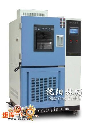
Ozone Box or Xeon lamp weather resistance test chamber
Published:2011/9/7 8:39:00 Author:Vicky | Keyword: Ozone Box, Xeon lamp weather resistance test chamber
Ozone box specification
Type (CM)QL-100 QL-250 QL-500 QL-010
Size of workroom: :45*45*50 50*60*75 70*80*90 100*100*100
Measurement: 115*90*165 120*110*190 135*128*210 165*148*220
Power: 4.0(KW) 4.5(KW) 4.5(KW) 6.5(KW)
Temperature range: 0℃~70℃
Humidity range: ≥65%R.H
Ozone density: 50~1000pphm
Temperature fluctuation range: ±0.5℃
Experiment device: dynamic or static (alternative)
Sample shelf rotate speed: 360°(1 circle/minute)
Gas flow speed: 12~16mm/s
Temperature controller: imported LED displays P、I、D+S、S、R. micro-computer integrated controller Ozone Box
Time controller: high-accuracy hour, minute and second controller Ozone Box
Ozone density analysis: silent discharging tube
Safety protection: leakage of electricity, short circuit, overheat, overheating of motor, over-current protection (View)
View full Circuit Diagram | Comments | Reading(1036)
Simplified load current strength indicator circuit diagram
Published:2011/9/6 21:16:00 Author:Vicky | Keyword: load current strength indicator
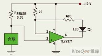
The light strength in the picture is proportional to the load current. The purpose of designing the circuit is to provide a very compact circuit to take the place of electricity meter of 12 V power line in some astronomical devices. The devices contain small-power heating components of invisible working state. However, when the heater is connected, LED would send out light to indicate clearly that they’re connected and working.
The circuit analysis is very simple. The voltage of the two ends of 22ohms resistance is the same with the voltage of the two ends of RSENSE. The current going through the 22 ohms resistance is the same with the current going through LED. Therefore, as to the parameter given by the picture, the current of LED current equals 0.05/22 of the load current. When the load current changes from 200mA to 6.6A, the light of LED becomes fully lighted from weak (confined by 680 ohms resistance).
(View)
View full Circuit Diagram | Comments | Reading(1086)
Full-bridge power conversion circuit
Published:2011/8/31 2:25:00 Author:John | Keyword: Full-bridge power conversion

When high power output is needed, full-bridge power conversion circuit is generally used. The figure shows the full-bridge power conversion circuit. As pointed out above, power transistor in the half-bridge power conversion circuit can withstand a maximum voltage which is half of that in the push-pull working transistor. However, if the output power requirements are of the same, the working current for the transistor will increase greatly. Full-bridge power conversion circuit has both advantages of those two circuits. It is able to maintain the power switching devices bearing down just like a half-bridge circuit, and it is also able to have small current-carrying characteristics just like a push-pull circuit.
(View)
View full Circuit Diagram | Comments | Reading(1195)
the reflect meter circuit composed of monolithic broadband phase-difference measurement system AD8302
Published:2011/8/26 19:58:00 Author:Ariel Wang | Keyword: reflect meter , monolithic, broadband, phase-difference
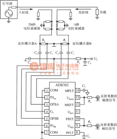
It is the reflect meter circuit composed of monolithic broadband phase-difference measurement system AD8302.You can work out at the reflection coefficient y by measuring the incident load signal and the gain of the reflected signal from the load.The calculation formula of the reflection coefficient is:y=the reflected voltage/the incident voltage=(ZL-ZO)/(ZL+ZO).In the formula,ZL represents the load impedance by using the complex number.ZO is the characteristic impedance in the system.The reflection coefficient is used to count SWR.The reflection coefficient is usually represents by decibel.
(View)
View full Circuit Diagram | Comments | Reading(2750)
the instrumentation amplifier or mixer gain and phase difference circuit composed of AD8302
Published:2011/8/23 1:34:00 Author: | Keyword: instrumentation amplifier , mixer gain, phase difference
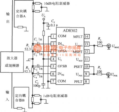

AD8302 is used to measure the phase difference and gain of the amplifier or the frequency mixing.The 20dB directional couple A and B do the sampling to the output and input signals of the amplifier.It can keep AD8302 signal level within the dynamic range by using 10dB resistance attenuator and 1dB resistance attenuator.To obtain the best performance,the power level POPT equals -30Bm(-43dBv) when two channels corresponding to the 50Ω characteristic impedance.The coupling coefficient and the attenuation coefficient of channel A and B is determained by the formula:in the formula,CA and CA are the coupling coefficient.LA and LB are the attenuation coefficient.GNOM is the nominal gain of the amplifier.
(View)
View full Circuit Diagram | Comments | Reading(1643)
Internal short-circuit measurement circuit of the coil
Published:2011/9/2 3:17:00 Author:Christina | Keyword: Internal short-circuit, measurement circuit, coil
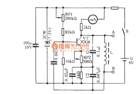
When the stator coil of the electromotor is in the local short-circuit state, you can not measure it by using the multimeter. The test circuit in the figure can complete the short-circuit test of the coil. The capacitive three-point oscillator circuit is composed of the transistor VT, the inductance coil L and the capacitors C1 and C2. When the measured stator coil is connected with the A and B of the oscillation circuit, the measured stator coil has the high-impedance if there is no short-circuit fault, it will not influence the operation of the oscillator, the pointer of the milliammeter has no action. When the measured stator coil has short-circuit fault, When it is connected with the A and B of the oscillation circuit, the Q value of the oscillation loop will reduce.
(View)
View full Circuit Diagram | Comments | Reading(3590)
Deep well water level detection sound and light alarm circuit
Published:2011/8/30 2:31:00 Author:Christina | Keyword: Deep well, water level, detection, sound, light, alarm circuit
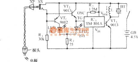
As the figure shows, it is composed of the conductive type probe, the electronic switch and the frogs sound circuit. It can be used in the detection of the water level of the wells or mines, when the probe touches the groundwater, the light-emitting diode will send out the green light, and the circuit will output the sound of forgs. The circuit is simple and practical, the volume is small and exquisite.
(View)
View full Circuit Diagram | Comments | Reading(1566)
The circuit of piezoelectric accelerator being used in impact test
Published:2011/8/23 22:12:00 Author:Borg | Keyword: piezoelectric accelerator, impact test
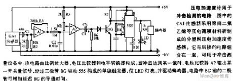
In the figure, GA1 sensor is a plastic piezoelectric accelerating sensor which is made of PVDF and other materials. It can be used in the impact test device when it is combined with the following circuit. The circuit consists of the proportion amplifier, voltage comparator and LEV converter. When the impact reaches certain value, the comparator A2 is outputting a switch volume signal, after the single steady trigger composed of 555 is driven by triode BG, the LED light is glowing, and the buzzer is driven. (View)
View full Circuit Diagram | Comments | Reading(1111)
AN5560 50/60Hz identification integrated circuit
Published:2011/8/23 22:37:00 Author: | Keyword: 50/60Hz, identification, integrated circuit
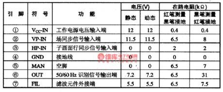
The AN5560 is designed as the 50/60Hz identification integrated circuit that is produced by the Panasonic company, and it can be used in the large-screen multi-system picture in picture color TVs as the field frequency identification device.
1.Features
The AN5560 is composed of the sub-screen horizontal and vertical sync signal processing circuit, the 50/60HZ field frequency identification processing circuit. And this IC uses the single row 7-pin package, the pin function and data are as shwon in table 1-20.
(View)
View full Circuit Diagram | Comments | Reading(828)
Water tower water level wired telemetry remote control device
Published:2011/8/26 2:01:00 Author:TaoXi | Keyword: Water tower, water level, wired, telemetry, remote control
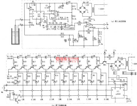
The water tower water level wired telemetry remote control device is as shown in the figure. This wired telemetry remote control device has two monitor duty parts. This circuit can monitor the water level of the tower, and it can control the water level to ensure the normal water supply and water saving , so it has the certain using value.
(View)
View full Circuit Diagram | Comments | Reading(2314)
The FM-RTFQl-868/433/315 MHz FM emitter module
Published:2011/8/23 22:37:00 Author:qqtang | Keyword: emitter module
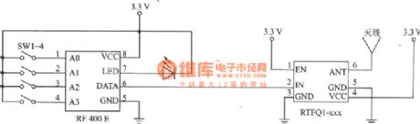
FM-RTFQl-xxx is a high-efficiency FM emitter. The types of the series are FM-RTFQl-315 MHz, FM-RTFQ1-433 MHz and FM-RTFQl-868 MHz, and its coupled receivers are FM-RRFQ1-315 MHz, FM-RRFQl-433 MHz和FM-RRFQl-868 MHz. They are fitted in the wireless secure system, car alarm and remote control/test. The features of the circuit are: the working frequency is 315/433/868 MHz; emitting distance is 250m; data transmitting speed is 9.67 Kb/s; power supply voltage is 2.1~4.0V; the maximum power supply current is 8mA, the maximum standby current is 100mA.
(View)
View full Circuit Diagram | Comments | Reading(1295)
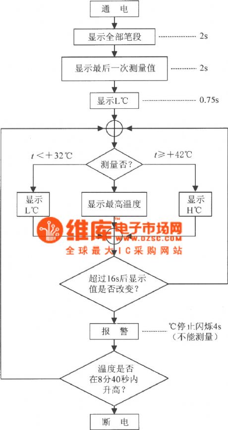
The digital thermometer circuit composed of highly precise micro medical digital clinical thermometer HT7500
Published:2011/8/13 1:43:00 Author:qqtang | Keyword: digital thermometer, digital clinical thermometer
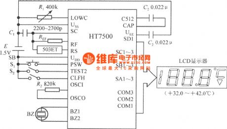
View full Circuit Diagram | Comments | Reading(1983)
The wide range digital capacitor gauge(NE555, CD4017 and MC14553B)
Published:2011/8/14 22:07:00 Author:qqtang | Keyword: wide range, digital capacitor gauge
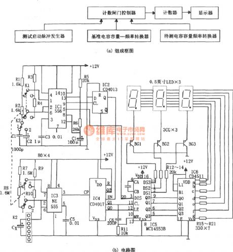
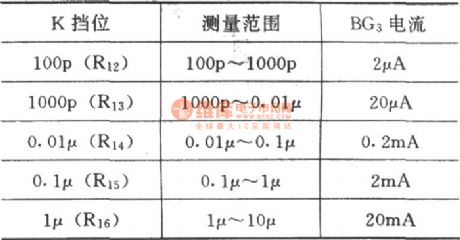
In the figure is a wide range digital capacitor gauge(NE555, CD4017 and MC14553B). The gauge consist of the pulse generator, reference capacitor volume-frequency converter, capacitance volume-frequency converter under test, counting controller, counter and display circuit, etc. The pulse generator is a multi-resonance oscillator which consists of the IC1, R1, R2 and C1(R3, R4 and C2), its oscillating is f1= 1.44/(R1+2R2)C1, or f2=1.44/(R3+2R4)C2. The upper edge of the pulse output by 9-pin makes the D trigger IC2 (CD4013) output terminal Q generate a low LEV.
(View)
View full Circuit Diagram | Comments | Reading(1905)
The multi-meter with additional field intensity meter circuit
Published:2011/8/13 1:14:00 Author:qqtang | Keyword: multi-meter, field intensity meter

View full Circuit Diagram | Comments | Reading(1046)
The capacitor (higher than 100pF) selecting circuit
Published:2011/8/13 1:16:00 Author:qqtang | Keyword: capacitor, selecting circuit
View full Circuit Diagram | Comments | Reading(878)
The application circuit of the single chip wide frequency band phase difference test system AD8302
Published:2011/8/14 22:38:00 Author:qqtang | Keyword: application circuit, single chip, phase difference, test system

The AD8302 application circuit is shown in the figure. R1 and R2 are the input terminals. R3 is the load of the UREF output terminal. C1 and C4 are the AC input coupling capacitor, C2 and C3 are the filtering capacitors, C5 and C6 are the power supply decoupling capacitors. S1 is the gain test pattern/comparator pattern selecting switch, by pulling S2 to gear a, the phase difference test pattern; when it is pulled to gear b, the comparator pattern is chosen, PSET terminal sets the voltage. (View)
View full Circuit Diagram | Comments | Reading(1065)
| Pages:26/101 At 202122232425262728293031323334353637383940Under 20 |
Circuit Categories
power supply circuit
Amplifier Circuit
Basic Circuit
LED and Light Circuit
Sensor Circuit
Signal Processing
Electrical Equipment Circuit
Control Circuit
Remote Control Circuit
A/D-D/A Converter Circuit
Audio Circuit
Measuring and Test Circuit
Communication Circuit
Computer-Related Circuit
555 Circuit
Automotive Circuit
Repairing Circuit