
Measuring and Test Circuit
Index 23
Power polarity tester
Published:2012/8/24 22:46:00 Author:Ecco | Keyword: Power polarity, tester
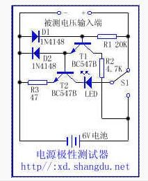
This circuit can detect positive and negative polaritywith the power supply between 3V-30V and LED indicator. The test circuit is a constant current source. When the polarity of inputmeasured power iscorrect, T1 , T2are also turned o , the LED emitslight. The diode D2 allows T2 base voltage to maintain constant current . Thus, regardless of the size of conduction currentfromT1, T2will substantially send constant current. If the measured powerhas opposite polarity, the diode D1 is turned on, T1, T2 arecut off, LED goes out , the switch S1 can self-test the internal circuit of LED.
(View)
View full Circuit Diagram | Comments | Reading(1980)
Working performance test circuit of three-terminal regulator IC
Published:2012/8/24 21:47:00 Author:Ecco | Keyword: Working performance, test circuit, three-terminal regulator IC
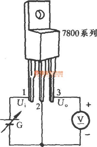
Three terminal regulator's pin ① and pin ② are added DC voltage (it uses adjustable DC Power G in Figure), but people must pay attention to the polarity of G , Ui should be at least higher 2V than regulator regulator value U, but the maximum should not exceed 35V. When multimeter is in DC voltage block to measure the voltage between pin ③ and pin ②, the value is stable voltage of the regulator. (View)
View full Circuit Diagram | Comments | Reading(1202)
Three - phase power supply phase sequence / open phase detector
Published:2012/8/24 22:28:00 Author:Ecco | Keyword: Three - phase , power supply , phase sequence, open phase, detector
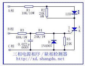
It is mainly used to detect the three-phase AC power wiring with phase loss and correct phase sequence or not. Circuit schematic is shown in thefigure, in the figure, if the A -phase ( 1 ), C phase ( 3 ) , B phase ( 2) are respectively connected to the thyristor A , G, and K electrode, thyristor T will get conduction in singlephase half cycle, the light - emitting diode will emit normal light, when the three-phase phase sequence of connections A, B, C is incorrect, the conduction time of the triac T will become shorte , the average current decreases and LED brightness is also greatly reduced.When one or two phasesaremissed inthe three-phase AC, SCR iscut off, LED goes ou, the values of R3, R4 and C will determine the length of the delay time t.
(View)
View full Circuit Diagram | Comments | Reading(7858)
Ordinary thyristor measured by battery
Published:2012/8/23 22:51:00 Author:Ecco | Keyword: Ordinary thyristor , battery
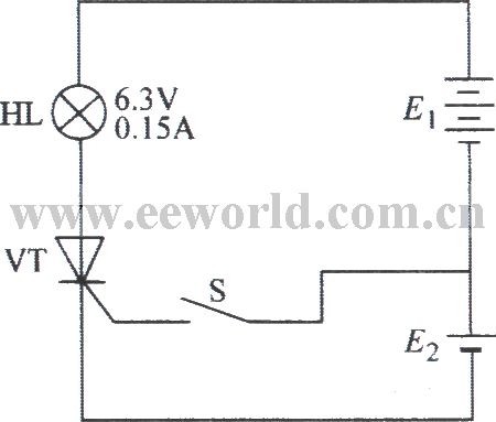
It takes four 1.5V batteries connected in series, then switch S is connected, E1 cathode is connected to anode of ordinary thyristor VS by lamp HL. E2 negative pole is connected to VT cathode. Close the S, HL is not extinguished. Because the lamp resistance is small, the current flowing through VT is sufficient to maintain triggered conduction current. Only disconnecting the anode or cathode connection of the thyristor, VT will shutdown, HL is extinguished.
(View)
View full Circuit Diagram | Comments | Reading(1283)
Leakage Ground Fault point measuring by Clamp meter
Published:2012/8/23 22:36:00 Author:Ecco | Keyword: Leakage , Ground Fault point, Clamp meter
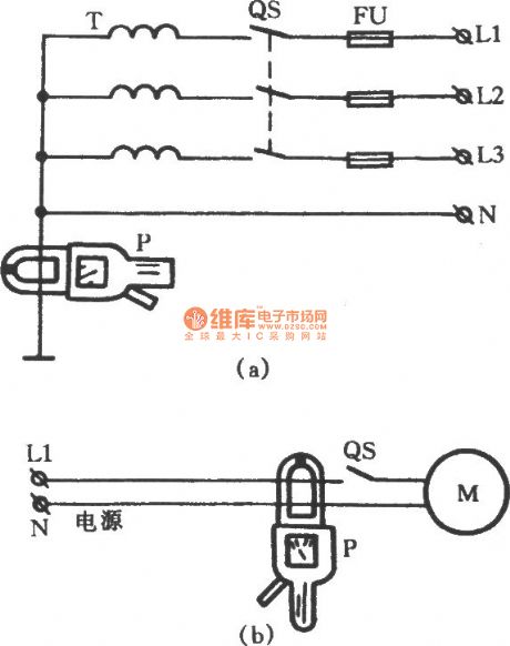
When the distribution lines or motor control equipment occursleakage Ground Fault, it is more difficult to identify the specific ground fault point. But Clamp ammeter canmeasure leakage ground fault without power outage andwiring,the circuit isshown as the figure.
(View)
View full Circuit Diagram | Comments | Reading(1847)
A part of product detector circuit composed of LF198 and LM122H
Published:2012/8/23 22:27:00 Author:Ecco | Keyword: product detector
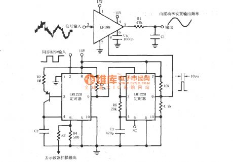
Synchronous clock signal is input to a cascade of timer circuit composed of two LM122H, then the synchronization clock is converted to the desired width of the pulse (Fig. 10μs) which will be add to LF198 LOGIC end (8 feet) as the sampling and holding control signal . The signal is input LF198's pin 3. The input signal contains a large number of noise component with magnitude higher than the useful signal, after the detector, the output signal's noise is filtered off, a pure signal will be output. The value of R3 should make 6-pin voltage be 0 ~~ 3V.
(View)
View full Circuit Diagram | Comments | Reading(2249)
Time incremental sampling differential measurement circuit composed of SMP04 and instrumentation amplifier
Published:2012/8/23 20:58:00 Author:Ecco | Keyword: Time incremental, sampling , differential , measurement circuit, instrumentation amplifier
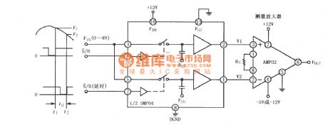
The circuit is used for measuring the difference of signal voltage at the different time points, that is the difference between voltages V1 and V2 at t1 and t2. Because the circuit uses the sampling and maintaining amplifier with the same package of SMP04, the symmetry of the circuit is good. The signal is output by SMP04, then it is sent to the instrument amplifier AMP02 for differential amplification, RG is used to set the instrument amplifier gain. VOUT = G (V1-V2), G = 50k/RG +1.
(View)
View full Circuit Diagram | Comments | Reading(1324)
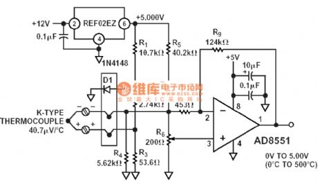
0-500 degree K thermocouple temperature measurement circuit
Published:2012/8/15 23:06:00 Author:Ecco | Keyword: 0-500 degree , K , thermocouple , temperature measurement
View full Circuit Diagram | Comments | Reading(4149)
Analog capacitance meter ( CD4013 )
Published:2012/8/17 1:43:00 Author:Ecco | Keyword: Analog capacitance meter
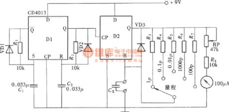
With a dual D flip-flop CD4013, a trigger and the measured capacitor form a monostable multivibrator toproduce the output pulse, the output pulse width,current average value and of the capacitance of the measuredcapacitor areproportional. The other flip-flop can form a multivibrator to generate the trigger pulse. An IC can form a simple capacitance meter. The measuring range : l00pF ~ lμF.
(View)
View full Circuit Diagram | Comments | Reading(5463)
Acousto-optic detector circuit to measure the crystal
Published:2012/8/15 22:30:00 Author:Ecco | Keyword: Acousto-optic , detector , measure , crystal
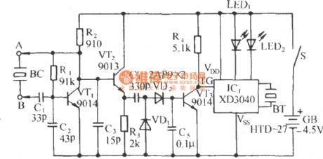
The circuit is shown in Figure, which consists of capacitance three-point oscillator, isolation level, voltage doubler rectifier circuit and stereo sound circuit and flash display circuit. It can detect the crystal's goodness or badness, good crystal will issue the sound of Didi ... , and LED1, LED2 will be blinking; bad crystal will not issue audible and visual information.
(View)
View full Circuit Diagram | Comments | Reading(1452)
Analog frequency meter circuit
Published:2012/8/15 22:10:00 Author:Ecco | Keyword: Analog , frequency meter
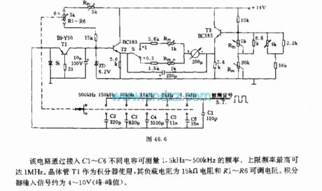
The circuit can measure the frequency between 1.5kHz ~ 500kHz by connecting C1 ~ C6 different capacitors. The maximum frequency is up to 1MHz. Transistor T1 can be used as the integrator, and its load resistor is 15kΩ resistor and R1 ~~ R6 adjustable resistors. Integrator's input signal is about 4 to 10V ( peak - peak value).
(View)
View full Circuit Diagram | Comments | Reading(3423)
Electrostatic detection of acousto-optic alarm circuit
Published:2012/8/15 22:59:00 Author:Ecco | Keyword: Electrostatic detection , acousto-optic alarm
The circuit is shown as the chart. It consists of electrostatic induction electronic switch and sound circuit. When the electrostatic field exists in the peripheral environment of computer, the circuit can detect the presence of static and issue the sound of beep , please attention , at the same time , the light-emitting diode will be lit to draw people's attention to the safe use of the computer or CPU chip.
(View)
View full Circuit Diagram | Comments | Reading(1499)
Thermistor electronic thermometer circuit diagram
Published:2012/8/16 22:17:00 Author:Ecco | Keyword: Thermistor, electronic thermometer
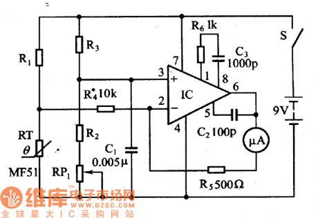
The thermistor RT and R1 , R2, R3 and RP1 form a temperature measurement bridge. When temperature is at 20 ℃, using R1, R3 and adjusting RP1 can allow bridge to keep balance. When temperature rises, the resistance of the thermistor RT reduces, the bridge in an unbalanced state, the imbalanced voltage output by bridge is amplified by operational amplifier, then the amplified imbalanced voltage causes corresponding deflection of microammeter connected to the op amp feedback circuit. The resistance of the thermistor is between 500 ~ 5000Ω.
(View)
View full Circuit Diagram | Comments | Reading(4485)
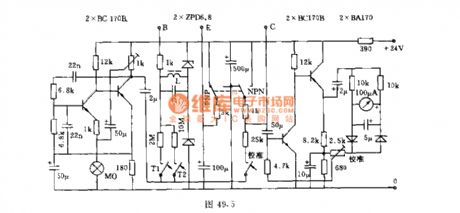
Low humidity detection circuit diagram composed of CGS ceramic humidity sensor
Published:2012/8/16 0:51:00 Author:Ecco | Keyword: Low humidity , detection circuit , CGS , ceramic , humidity sensor
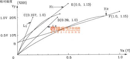
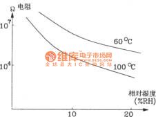
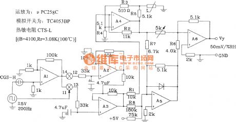
The op amp: μPC258CAnalog switch: TC4083BPThermistor: CTS-L (B=4100, Rr=3.08K, 100℃)
Moisture characteristic curve and the relativecurve at 60 ℃ and 100 ℃ are shown in the figure:
(View)
View full Circuit Diagram | Comments | Reading(1526)
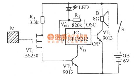
Highly sensitive electrostatic detector circuit
Published:2012/8/15 2:18:00 Author:Ecco | Keyword: Highly sensitive , electrostatic detector
The circuit is composed of electrostatic induction electronic switch and transistor music IC sound circuit. It can be used to detect the exist of electrostatic field in engine room or around and discharge the static on computer or chip. The detection is accurate, and the circuit is compact and has highly practical value.
(View)
View full Circuit Diagram | Comments | Reading(3344)
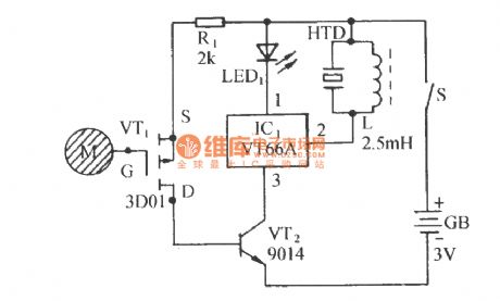
Straight district transistor A measuring instrument circuit
Published:2012/8/15 2:28:00 Author:Ecco | Keyword: Straight district, transistor A , measuring instrument
After the determinand transistor's pins are connected to B , E , C, then people can use the switch to select the tube type: PNP or NPN, and the β value of the transistor can be directly read from 100μA dial instrument. When switch T1 is closed, measurement range β = 0 ~ 100; when T2 is closed, measurement range β = 0 ~ 500. The inductance coil L in the circuit is wound by 0.2mm copper with 1550 turns.
(View)
View full Circuit Diagram | Comments | Reading(1045)
Direct-reading LC meter circuit
Published:2012/8/13 22:23:00 Author:Ecco | Keyword: Direct-reading , LC meter
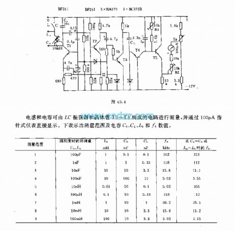
Inductor and capacitor can be tested by the circuit composed of LC oscillator and transistors T1 ~~ T5, and displayed directly by 100μA pointer instrument. The following table shows the measurement range and values of capacitors C0 , CL , L0 and f0.
(View)
View full Circuit Diagram | Comments | Reading(2342)
Simple regulator tester circuit
Published:2012/8/13 22:37:00 Author:Ecco | Keyword: regulator , tester

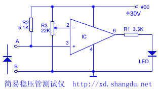
Simple regulator tester circuit can easily test the value of regulator, and its production is very convenient.
The schematic is shown as the following figure. ICcan select F007, CA3140, μA741 amplifiers, R3 Selects 22K straight sliding potentiometer,and the voltage should be marked on the shell according toaccording to the positive supply voltage required by R3. In addition , due to the limitations of the IC operating voltage, the lcircuit is imited to the measure theregulator tube with valuebeing lower than30V.
(View)
View full Circuit Diagram | Comments | Reading(1157)
Junction field effect transistor matching test circuit
Published:2012/8/13 22:41:00 Author:Ecco | Keyword: Junction , field effect transistor, matching test circuit
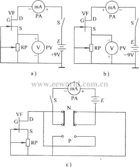
Figure a shows the circuit which can test matchingN-channel junction field effect transistor tube. Figure b shows the circuit which can test the matchingP-channel junction field effect transistor tube . Figure a shows the circuit which can testmatching N, P junction field effect transistor tube.
(View)
View full Circuit Diagram | Comments | Reading(1898)
High-power transistors test circuit with multimeter
Published:2012/8/13 22:47:00 Author:Ecco | Keyword: High-power transistors, multimeter, test circuit
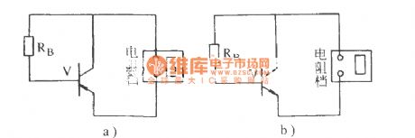
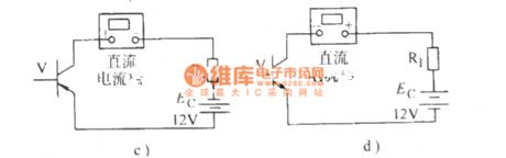
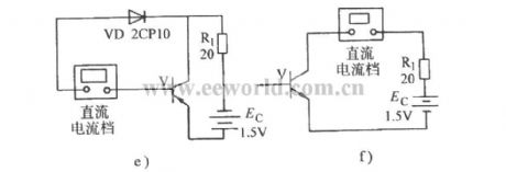
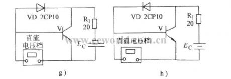

Figure a, bare used to testthe amplification of high-power transistor . Figure c, dare used to testthe Iceo of high-power transistors. Figure E, fare used tothe hFE of high-power tube. Figure g, hare used to test high-power transistor UB . Figure i, kare used totest high-power transistors UBES and UCES.
(View)
View full Circuit Diagram | Comments | Reading(1810)
| Pages:23/101 At 202122232425262728293031323334353637383940Under 20 |
Circuit Categories
power supply circuit
Amplifier Circuit
Basic Circuit
LED and Light Circuit
Sensor Circuit
Signal Processing
Electrical Equipment Circuit
Control Circuit
Remote Control Circuit
A/D-D/A Converter Circuit
Audio Circuit
Measuring and Test Circuit
Communication Circuit
Computer-Related Circuit
555 Circuit
Automotive Circuit
Repairing Circuit