
Measuring and Test Circuit
Index 24
Transistor performance quick test circuit
Published:2012/8/12 21:29:00 Author:Ecco | Keyword: Transistor , performance, quick test
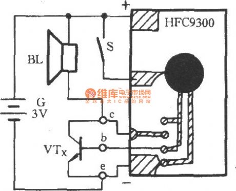
The figure transistor performance quick test circuit. In the figure, HFC9300is music IC which stores a song. BL is a speaker , S is the trigger switch . VTx is a transistor undertest. When VTx inserts into the socket, and thepin collectorinsertsinto c , the base inserts into b , the emitter inserts into e . If VTx is a good tube, BL will play a beautiful song; if VTx is a bad tube , then BL keeps silence.
(View)
View full Circuit Diagram | Comments | Reading(1317)
DS2438 used for measuring traction battery packs circuit
Published:2011/12/2 1:21:00 Author:May | Keyword: traction battery packs, measuring
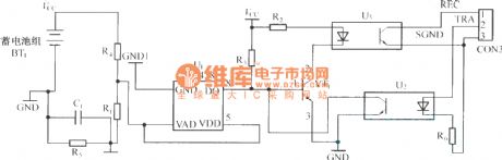
Traction battery packs test chip produced by America Dallas company has rich function, and itis convenient to achieve monitoring the running state of electric motor car’s traction battery packs.
DS2438 can beused for monitoring of various kinds of traction battery packs. The utility power used in electric motor car is traction battery packs composed of multiple power battery connecyed in series, parallel. The performance of each power battery directly affectsthe characteristic of whole traction battery packs. So in practical application, we should make on-line real-time detection to each power battery. And each power battery should connectwith a piece of DS2438, and their data terminal can be articulated to a bus. The power supply source of DS2438 can come from tested power battery itself. The potential of DS2438 signal end DQ is to the ground of this DS2438. The potential of reference ground is different, so it must cause the difference of potential of DS2438 signal end DQ inthe same reference point. It is shown in the diagram.
(View)
View full Circuit Diagram | Comments | Reading(1715)
Test probe circuit
Published:2011/11/10 1:35:00 Author:May | Keyword: Test probe
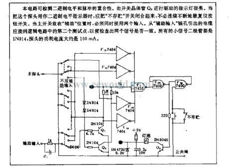
This circuit can detect repeatability of bubart system level and pulse. Because indicator light drived by switch transistor Q3 is very light, whenthis probe is used as binary system level indicator,the not stored switch should be closed,it does notneed to press reset button switch continuously. When the main switch isput on aide position, peopel must use two input together. Cable extract from aide input jack should beconnected to logic circuit's second test point to inspect the two signal being consistent or not. All small signal diodes are 1N914, and the probe power current is about 160mA.
(View)
View full Circuit Diagram | Comments | Reading(1437)
Seedling raising shed humidity and temperature monitor circuit
Published:2011/11/23 2:23:00 Author:May | Keyword: Seedling raising shed, humidity and temperature monitor
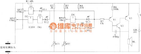
When growing seeding in seeding raising shed, the main thing is to grasp thehumidity and temperature of hot bed soil. Seeding raising shed humidity, temperature monitor introduced in this example can send out voice, light alarm signal when the soil in hot bed is too dry or too wet or the temperature in shed is too high, too low. It can remind the farmer to treat this situation in time.
This seedling raising shed humidity, temperature monitor circuit consists of soil humidity monitor circuit, temperature monitor circuit and voice alarm circuit. The circuit is shown in the diagram.
Theselection of components and parts
R1~R6 adopts 1/4W metal film resistor or carbon film resistor
RT1 and RT2 all adopt negative temperature factor thermal resistor (the resistance in normal temperature is about 3kΩ)
RP1~RP4 all adopt organic solid potentiometer
C adopts ceramic dielectric capacitor or glass glaze condenser
VL1~VIA all adopt φ3mm high brightness LEDs; VL1 and VL3are green, VL2 and VIAare red
V1 adopts S9012 or 3CG21 type silicon PNP transistors; V2 adopts S9011 or 3DG6 type NPN transistor; V3 adopts S8550 or 3CG8550 type silicon PNP transistor
IC adopts CD4069 or CC4069, MC14069 type six not gate IC
BL adopts 0.25W, 812 dynamic loudspeaker
GB uses low capacity non-maintaining storage battery or four AA battery
S adopts small type single-pole tumble switch
The two poles of temperature detection probe make up to adopt graphite carbon piece in D size dry battery (using insulating board to set, the distance between two poles is 4cm, wire lead weld on the copper cap of graphite carbon piece). (View)
View full Circuit Diagram | Comments | Reading(1481)
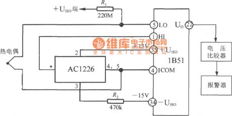
Detection thermocouple open-circuit fault(isolated thermocouple cold compensation and signal conditioner 1B51) circuit
Published:2011/8/30 21:50:00 Author:Jessie | Keyword: Detection thermocouple, open-circuit fault, isolated thermocouple , cold compensation , signal conditioner
View full Circuit Diagram | Comments | Reading(1298)
50MHz opto-electrical detecting circuit
Published:2011/12/1 0:46:00 Author:May | Keyword: opto-electrical, detecting
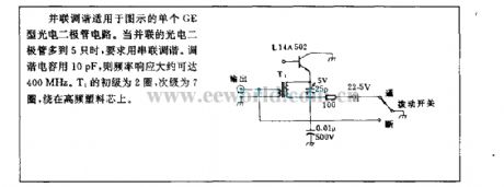
Parallel-tuned circuit is suitable for single GE photod circuit shown in the diagram. When the number of paralled photods isup to five, it requires to use series tuning. Tuning capacitor uses 10pF, and frequency response can reach about 400MHz. T1's primaryis 2 laps,and the secondaryis 7 laps, they are wound on high frequency plastic core.
(View)
View full Circuit Diagram | Comments | Reading(997)
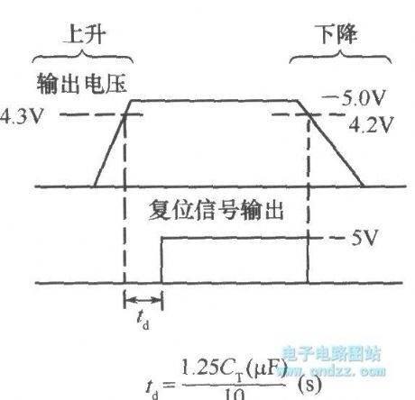
Oversee 5V voltage circuit composed of microcomputer system reset integrated chip NJM2103
Published:2011/11/10 1:16:00 Author:May | Keyword: Oversee 5V voltage, microcomputer system , reset integrated chip
View full Circuit Diagram | Comments | Reading(809)
Metering circuit using PbS, PbSe
Published:2011/11/11 2:05:00 Author:May | Keyword: Metering, PbS, PbSe
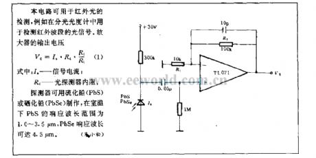
This circuit canbeused for detecting infrared light, for example, it is used for detecting infrared band light signal in spectrophotometer. Amplifier output voltage Vo=Is·Rd·Rf/Ri (1)wherein : Is-signal current; Rd-optical detector essential resistance Dector can bemade by lead sulphide (PbS) or lead selenide (PbSe), and at room temperature, PbS response wave length range is 1.0~3.5µm, PbSe reponse wave length can reach 4.5µm. (ZhuXiaosong)
(View)
View full Circuit Diagram | Comments | Reading(2393)
Tv power photo observation circuit using LED
Published:2011/11/30 20:12:00 Author:May | Keyword: Tv power photo observation, LED
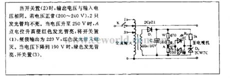
When switch places (2) , output voltage is the samewith theinput voltage. If voltage is normal (200~240V), two luminotrons are not bright. When voltage rises to 250V, point A 's potential rises to make red luminotrons birght, switch places (1) tomake output be 220V, red luminotrons go out again. When voltage drops to 190V, green luminotronsarebright, switch places (3).
(View)
View full Circuit Diagram | Comments | Reading(813)
LED display electronic voltmeter circuit
Published:2011/11/3 1:04:00 Author:May | Keyword: LED display, electronic voltmeter
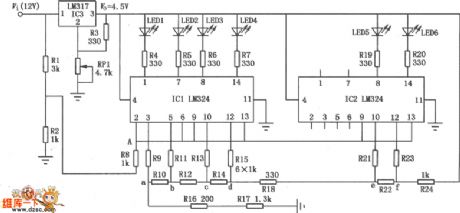
This circuit mainly consists of six light-emitting diodes, two integrated circuits and some resistors. It can display the voltage ofcar, motorcycle or electric bicycle batteriesaccording tothe quantityof light-emitting diode lights. Its usage is very convenient.
(View)
View full Circuit Diagram | Comments | Reading(2222)
Relay detection circuit diagram
Published:2011/11/3 22:51:00 Author:May | Keyword: Relay detection
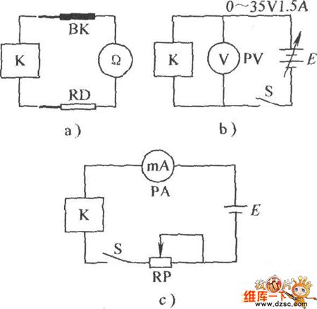
Diagram a is resistor to measure coil.Multimeter chooses R×100 Ω file. Diagram b is relay to measure the pull-in voltage and releasing voltage, adjusting regulated power supply risegradually from 0V. When you can hear armatureiron da sound and itpulls in, at this time voltmeter PV displayed voltage is pull-in voltage; then adjusting regulated power supply buttopn will makevoltage gradually drop, when youheararmatureiron ka sound and the realy releases, the voltage is relay releasing voltage, diagram c isthe relay to measure pull-in current and releasing current. The method is similar to diagram b.
(View)
View full Circuit Diagram | Comments | Reading(929)
Environmental noise monitoring circuit
Published:2011/11/3 1:26:00 Author:May | Keyword: Environmental noise monitoring
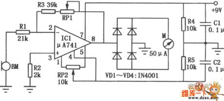
Environmental noise monitoring circuit is shown in the diagram. It mainly consists of high-gain operational amplifier μA741. The noise signal measured and displayed by ampere meter. Operational amplifier IC1 isconnected as thenoise amplifier, then thedetected noisesignla is added to IC1's reverse input end bymicrophone BM,then it is full-wave rectified by diodes VD1~VD4 after enlarging, finally it makesthe ampere meter deflection to display the strength of environmental noise. When it is adjusted, firstly, the two ends of microphone are short connected, then adjusting thezero potentiometer PR2 canmake ampere meter display 0. Adjusting potentionmeter PR1 can change ampere meter sensitivity.
(View)
View full Circuit Diagram | Comments | Reading(1216)
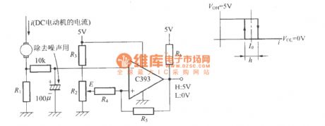
DC motor current detection circuit for adjusting over threshold or not
Published:2011/12/6 1:03:00 Author:Ecco | Keyword: DC motor , current detection , over threshold
View full Circuit Diagram | Comments | Reading(1065)
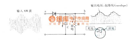
Diode detector circuit
Published:2011/11/30 2:22:00 Author:Ecco | Keyword: Diode detector
View full Circuit Diagram | Comments | Reading(1256)
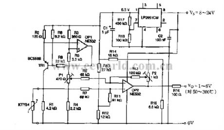
Temperature sensor measuring circuit
Published:2011/11/30 3:05:00 Author:Ecco | Keyword: Temperature sensor measuring
View full Circuit Diagram | Comments | Reading(1068)
Percentage ratio detector circuit
Published:2011/11/30 2:23:00 Author:Ecco | Keyword: Percentage ratio detector
View full Circuit Diagram | Comments | Reading(1404)
Relative humidity measuring instrument
Published:2011/11/30 2:20:00 Author:Ecco | Keyword: Relative , humidity measuring instrument
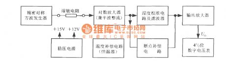
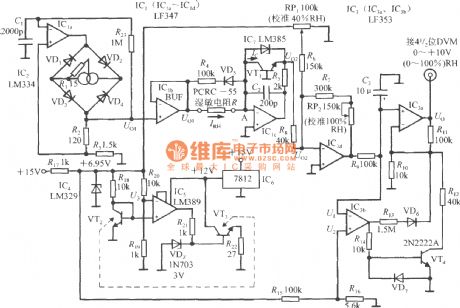
Relative humidity measuring instrument's circuitblock diagram
(View)
View full Circuit Diagram | Comments | Reading(1115)
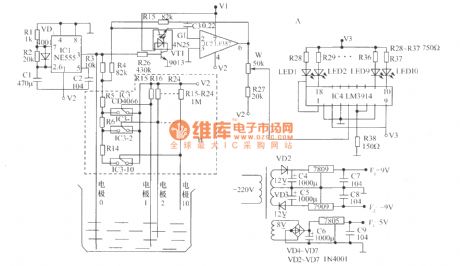
The AC voltage measuring circuit by carrier
Published:2011/11/1 21:18:00 Author:Ecco | Keyword: AC voltage, measuring circuit , carrier
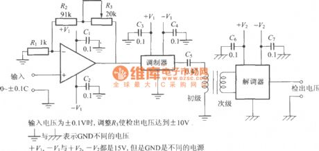
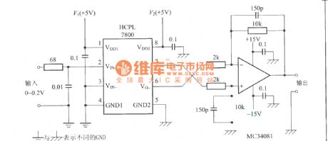
When the input voltage is ±0.1V, adjusting R3 can make the measuring voltage reach ±10V.
+V1, -V1, and +V2, -V2 are 15V, but GND uses different power supplies.
(View)
View full Circuit Diagram | Comments | Reading(2591)
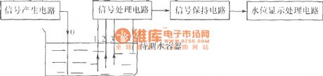
Water level detection circuit
Published:2011/11/7 20:40:00 Author:Ecco | Keyword: Water level detection
View full Circuit Diagram | Comments | Reading(1580)
The insulation DC voltage measuring circuit
Published:2011/11/1 21:11:00 Author:Ecco | Keyword: insulation, DC voltage, measuring circuit
View full Circuit Diagram | Comments | Reading(2325)
| Pages:24/101 At 202122232425262728293031323334353637383940Under 20 |
Circuit Categories
power supply circuit
Amplifier Circuit
Basic Circuit
LED and Light Circuit
Sensor Circuit
Signal Processing
Electrical Equipment Circuit
Control Circuit
Remote Control Circuit
A/D-D/A Converter Circuit
Audio Circuit
Measuring and Test Circuit
Communication Circuit
Computer-Related Circuit
555 Circuit
Automotive Circuit
Repairing Circuit