
Measuring and Test Circuit
Index 27
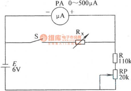
The microampere meter internal resistance test circuit
Published:2011/8/13 1:18:00 Author:qqtang | Keyword: microampere meter, internal resistance, test circuit
View full Circuit Diagram | Comments | Reading(1449)
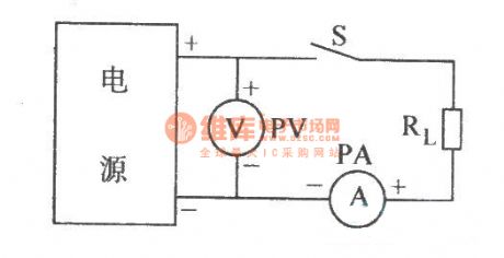
The power supply internal resistance measuring circuit
Published:2011/8/13 1:20:00 Author:qqtang | Keyword: power supply, internal resistance, measuring circuit
View full Circuit Diagram | Comments | Reading(908)
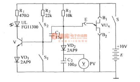
The single knot transistor speed test circuit (1)
Published:2011/8/13 1:21:00 Author:qqtang | Keyword: single knot, transistor speed test circuit
View full Circuit Diagram | Comments | Reading(1186)
The 3 working pattens of the single chip frequency phase difference test system of AD8302
Published:2011/8/13 1:29:00 Author:qqtang | Keyword: working pattens, single chip, phase difference, test system
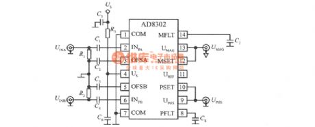
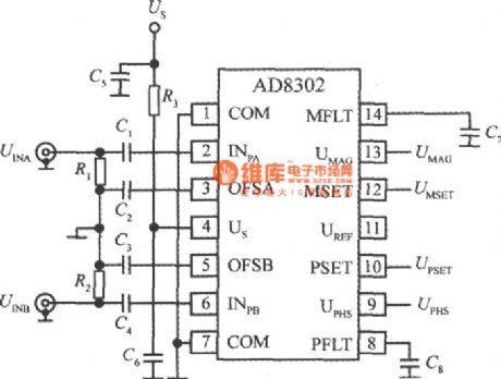
The test patten basic connection circuit of the single chip wide frequency band phase difference test system of AD8302:
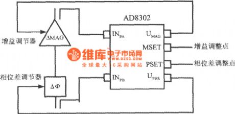
Comparator patten connection circuit:
Control patten connection circuit:
(View)
View full Circuit Diagram | Comments | Reading(1306)
Three-phase AC phase sequence detector circuit diagram
Published:2011/8/21 21:45:00 Author:Ecco | Keyword: Three-phase AC, phase sequence detector
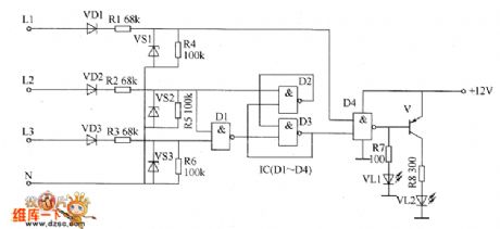
The three-phase alternating current phase detector circuit is composed of the phase sequence detection circuit, trigger control circuit and LED display circuit, and it is shown as the chart. Phase sequence detection circuit is composed of the rectifier diodes VD1 ~ VD3, resistors R1 ~ R6 and Zeners VS1 ~ VS3. Trigger control circuit consists of four NAND gate integrated circuit IC internal NAND gates D1 ~ D4. LED display circuit consists of NAND gate D4, LEDs VL1, VL2, transistor V and resistors R7, R8. R1 ~ R3 select the 1W metal film resistors: R4 ~ R8 select the 1/4W metal film resistors or carbon film resistors.
(View)
View full Circuit Diagram | Comments | Reading(21654)
The position detection circuit diagram for rotary transformer
Published:2011/8/21 22:26:00 Author:Ecco | Keyword: position detection , rotary transformer
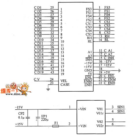
As the rotary transformer output contains the location information of the analog signal, it is required to process and turn into the digital corresponding location information, then it can control the chip interface with DSP. This requires a corresponding signal conversion circuit which is designed to use a dedicated rotary transformer(digital converter). The system selects the 19XSZ2413-S32-09-A rotary converter, and it is shown as the chart.
(View)
View full Circuit Diagram | Comments | Reading(1013)
long-distance encoding,decoding launch and receiving circuit MC145026,PT2262 circuit
Published:2011/8/25 20:21:00 Author:chopper | Keyword: long-distance, encoding, decoding launch, receiving circuit
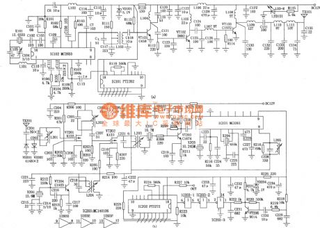
This circuit is the high-power transmitter which uses digital encoding chips (such as the MC145026, PT2262, etc.) to modulate the signals,and it is together with the high sensitivity receiver and decoding circuits which is match with encoding chips (eg,MC145027, PT2272, etc.) for long-distance wireless remote control, alarm and other purposes. The main technical parameters of transmitter: FM system; operation frequency is 36.1MHz; supply voltage is 12V; transmit power is 2 ~ 5W.
(View)
View full Circuit Diagram | Comments | Reading(3316)
Bearing fault detector circuit diagram 1
Published:2011/8/10 22:05:00 Author:Ecco | Keyword: Bearing fault detector
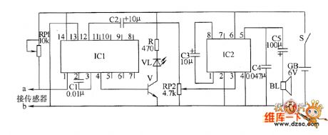
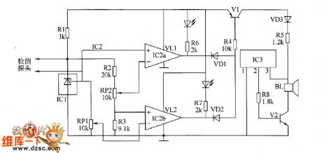
The bearing fault detector circuit is composed of the bearing detection sensor, signal processing circuit, transistor V, audio amplifier integrated circuit IC2, speaker BL and the RC element, and IC1, light-emitting diode VL, transistor are shown as the chart. RP1 is used to adjust the sensitivity of the signal processing circuit. RP2 is used to adjust the speaker output volume. R select the 1/2W carbon film resistor. RP1 uses the small synthetic membrane potentiometer without switch; RP2 uses the small synthetic membrane potentiometer with switch. C1 and C4 select the polyester capacitors; C2, C3 and C5 select the electrolytic capacitors with voltage in 16V.
(View)
View full Circuit Diagram | Comments | Reading(1569)
Adobe moisture detector circuit diagram 3
Published:2011/8/10 21:46:00 Author:Ecco | Keyword: Adobe moisture detector
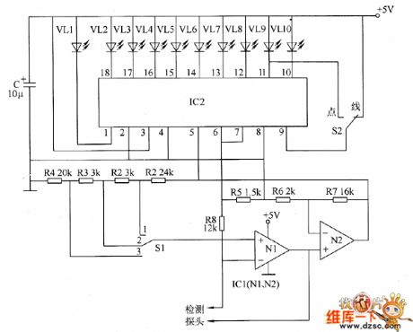
The adobe moisture detector circuit is composed of the detection input circuit and LED display circuit, and it is shown as the chart. The detection input circuit consists of the testing probe, operational amplifier integrated circuit IC1 (N1, N2), resistors R1 ~ R8 and water content measurement area selection switch S1. LED display circuit consists of the LED linear analog display driver integrated circuit IC2, LEDS VL1 ~ VL10 and point / line selector switch S2. R1 ~ R8 select the 1/4W carbon film resistors or metal film resistors. C select the aluminum electrolytic capacitor with voltage in 16V.
(View)
View full Circuit Diagram | Comments | Reading(1334)
Paper thickness detector circuit diagram
Published:2011/8/11 1:46:00 Author:Ecco | Keyword: Paper thickness detector
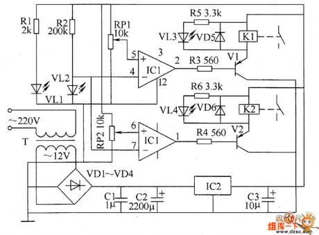
The paper thickness detector circuit is composed of the power supply circuit, infrared detection circuit and control implementation circuit, and it is shown as the chart. Power supply circuit consists of the power transformer T, rectifier diodes VD1 ~ VD4, filter capacitors C1 ~ C3 and three-terminal regulator IC2 and so on. Infrared detection circuit consists of the infrared emitting diode VL1, infrared receiver diode VL2, operational amplifier integrated circuit IC1 and the peripheral components. Control implementation circuit consists of the transistors V1, V2 and relays K1, K2 and so on. R1 ~ R6 use the 1/4W carbon film resistors or metal film resistors.
(View)
View full Circuit Diagram | Comments | Reading(1392)
Adobe moisture detector circuit diagram 2
Published:2011/8/11 1:27:00 Author:Ecco | Keyword: Adobe moisture detector
The adobe detector circuit is composed of the humidity detection sensor, voltage-regulator reference power supply, comparator, switch circuit and sound and light alarm circuit, and it is shown as the chart. Voltage-regulator reference power supply is composed of the resistor R1 and integrated voltage regulator IC1. Comparator circuit consists of integrated circuit IC2 and resistors R2, R3, potentiometers RP1, RP2 and so on. Switch circuit consists of the switch V1, diodes VD1, VD2 and resistor M and other components. Sound and light alarm circuit consists of the light-emitting diodes VL1, VL2, resistors R6, R7, music integrated circuit IC3, audio amplification tube V2 and speaker BL and so on.
(View)
View full Circuit Diagram | Comments | Reading(1374)
Adobe moisture detector circuit diagram 1
Published:2011/8/10 21:41:00 Author:Ecco | Keyword: Adobe moisture detector
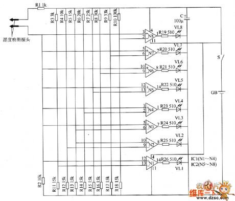
The adobe moisture detector circuit is composed of the humidity detection probe, op-amps N1 ~ N8 (IC1, IC2), light-emitting diodes VL1 ~ VL8 and resistors R1 ~ R26, and it is shown as the chart. R1 ~ R26 choose l / 4 W carbon film resistors or metal film resistors. C select the CD11 series of aluminum electrolytic capacitor with voltage in 16V. VL1 ~ VL3 and VL6 ~ VL8 select φ3mm red high-brightness light-emitting diodes; VL4 and VL5 use φ3mm green high-brightness light-emitting diodes. IC1 and IC2 select LM324 Quad op-amp circuit. CB chooses the 6 ~ 9V laminated battery.
(View)
View full Circuit Diagram | Comments | Reading(1005)
Bearing fault detector circuit diagram 2
Published:2011/8/10 22:23:00 Author:Ecco | Keyword: Bearing fault detector
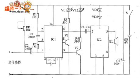
The bearing fault detection circuit is composed of the bearing detection sensors, signal processing circuit and sound and light circuit, and it is shown as the chart. Signal processing circuit consists of the input socket XS, voice integrated circuit IC1, capacitors C1 ~ C3, resistors R1, R2 and potentiometer RP. Sound and light is composed of the transistors V1, V2, LEDs VL1, VL2, audio power amplifier integrated circuit IC2, resistors R3, R4, capacitor C4, diodes VD1, VD2, and speaker BL. R1 ~ M select the 1/4W or 1/8W metal film resistors. RP uses the small synthetic membrane potentiometer or variable resistor.
(View)
View full Circuit Diagram | Comments | Reading(1690)
Humidity detection circuit diagram composed of H104R humidity sensor
Published:2011/8/15 1:09:00 Author:Ecco | Keyword: Humidity detection , humidity sensor
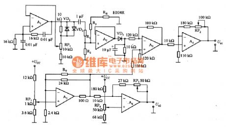
Figure 1 is the humidity detection circuit composed of H104R humidity sensor. In the circuit, the AC voltage is added to the humidity sensor, and the circuit consists of the oscillation circuit, buffer, rectifier circuit, temperature compensated differential amplifier circuit, humidity output amplifier circuit, temperature detection circuit,temperature output amplifier circuit. The circuit's power supply voltage is ± l2V, the oscillation frequency of the oscillation circuit is 1KHz. Compensation characteristics of the sensor is decided by R1, R2, R3. The temperature coefficient of RH humidity resistor H104R is 0.7% RH / ℃. Thermistor RT is commonly used in temperature compensation circuit.
(View)
View full Circuit Diagram | Comments | Reading(2635)
The infrared remote control detector
Published:2011/8/1 22:06:00 Author:TaoXi | Keyword: Infrared, remote control, detector
Infrared remote control detector
(View)
View full Circuit Diagram | Comments | Reading(806)
Remote control infrared detection circuit
Published:2011/8/4 1:44:00 Author:TaoXi | Keyword: Remote control, infrared detection
Remote control infrared detection circuit
The circuit in this figure can transport the signal of the detected target in long distance. The PC-1 is a pair of infrared diode and phototransistor. When the object obstructs the light of diode exposure to the photo-transistor, the photo-transistor will be in the cut-off state, and the signal is amplified and added to the load through the second pair of infrared diode and phototransistor. The second pair of infrared diode and phototransistor has the failure insurance effect.
(View)
View full Circuit Diagram | Comments | Reading(831)
The peak value detection circuit composed of μA741
Published:2011/7/29 4:38:00 Author:Borg | Keyword: peak value, detection circuit
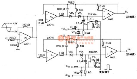
This is the peak value detection circuit composed of μA741. In all kinds of tests on the physical quantities converting into electric quantities with the sensor, the peak values should be tested when processing waveforms. In figure 8-1 is the peak value detecting circuit, whose detected negative/positive values are ±5V, the peak values are output by A4 and A5. The maintenance time of the circuit is decided by capacitor C1(C2), diode, VT1(VT2) grid and leakage current. The smaller these elements are, the longer the time will be.
(View)
View full Circuit Diagram | Comments | Reading(1406)
ZERO_POINT_WITH_OVERVOLTAGE_PROTECTION
Published:2009/7/14 21:37:00 Author:May
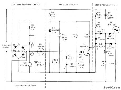
Used to protect voltage-sensitive load from excessive line voltage Switch section operates conventionally to turn on triac almost immediately after each zero crossing between half-cycles,For normal line voltages, SCR Q3 is off. When overvoltage condition is sensed during any half-cycle, SCR Q1 s turned on, discharging C2 and turning Q2 off. This allows Q3 to turn on and divert triac gate drive, removing power from load As long as overvoltage condition exists, Q1 is turned on each half-cycle and C2 is unable to charge enough to turn Q2 on,When overvoltage condition ceases, C2 charges to voltage set by D8 in about 20 ms, saturatingQ2 so Q3 turns off and Q4 turns on R2 can be set to allow line voltage variations from almost 0 to 11 v.-“Circuit Applications for the Triac,” Motorola, Phoenix, AZ, 1971, AN-466, p 14. (View)
View full Circuit Diagram | Comments | Reading(1932)
PEAK_AND_TROUGH_DETECTOR
Published:2009/7/14 21:35:00 Author:May
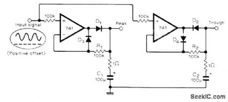
Uses only two opamps to detect peak and valley voltages of nonsymmetrical waveform. During valley period, D2 conducts and discharges C2 rapidly to lowest value of signal amplitude. C2 charges only slightly through D4 and R2 during positive peaks, thus retaining minimum voltage.-C. Spain, Precision Peak and Trough Detector, Wireless World, 0ct. 1977, p 65.
(View)
View full Circuit Diagram | Comments | Reading(3046)
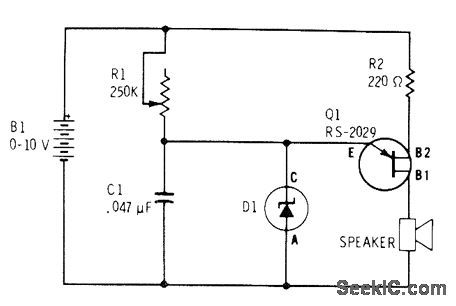
POSITIVE_PEAK_DETECTOR
Published:2009/7/14 21:33:00 Author:May
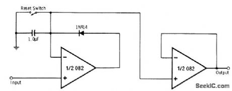
Circuit responds to and remembers peak positive excursions of input signal over period of time with first half of 082 dual opamp. Other half of opamp serves as voltage follower for isolating peak detector from output. Memory time is typically several minutes, depending on rate at which capacitor discharges due to its own leakage current, diode leakage current, opamp bias currents, and slight loading effect of voltage follower. Closing reset switch momentarily discharges capacitor in readiness for storing new peak value.-R. Melen and H. Garland, Understanding IC Operational Amplifiers, Howard W. Sams, Indianapolis, IN, 2nd Ed., 1978, p 96-97.
(View)
View full Circuit Diagram | Comments | Reading(0)
| Pages:27/101 At 202122232425262728293031323334353637383940Under 20 |
Circuit Categories
power supply circuit
Amplifier Circuit
Basic Circuit
LED and Light Circuit
Sensor Circuit
Signal Processing
Electrical Equipment Circuit
Control Circuit
Remote Control Circuit
A/D-D/A Converter Circuit
Audio Circuit
Measuring and Test Circuit
Communication Circuit
Computer-Related Circuit
555 Circuit
Automotive Circuit
Repairing Circuit