
Measuring and Test Circuit
Index 22
Brownout Voltage Tester
Published:2012/9/10 20:37:00 Author:Ecco | Keyword: Brownout, Voltage Tester

I used this circuit years ago to test AC line powered devices under 95vac line voltage conditions. It has a rating of 250 watts.
Source: discovercircuits (View)
View full Circuit Diagram | Comments | Reading(1002)
Shadow Activate Motion Detector
Published:2012/9/9 20:39:00 Author:Ecco | Keyword: Shadow , Activate , Motion Detector
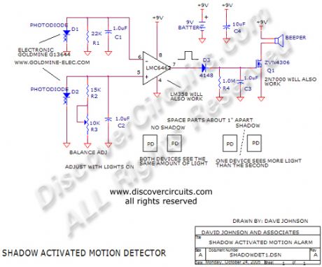
This circuit can sound an alarm when the shadow of a hand or arm moves over two small photo diodes.
Source: discovercircuits (View)
View full Circuit Diagram | Comments | Reading(1142)
AC Current Controls Hour Meter -- February 13, 2010
Published:2012/9/6 20:26:00 Author:Ecco | Keyword: AC Current, Controls, Hour Meter

Many systems require routine maintenance based on machine operation time. The circuit below is a simple way to turn on a hour meter whenever AC power is supplied to the machine. An inexpensive snap-on current transformer from Magnetics Inc, is used to detect the AC current.
Source: discovercircuits (View)
View full Circuit Diagram | Comments | Reading(2030)
Home Made Geophone Detects Foot Stomp
Published:2012/9/6 20:23:00 Author:Ecco | Keyword: Home Made , Geophone , Detects, Foot Stomp
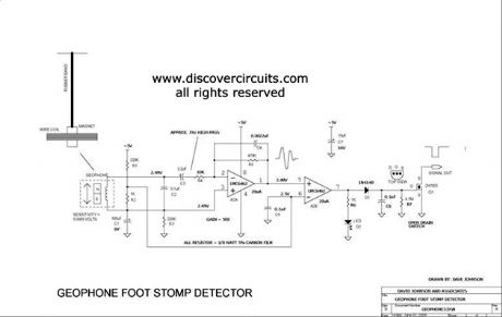
A home made geophone is made from a strong magnet, a coil of wire and a rubber band. The circuit is sensitive enough to detect the vibrations of a nearby foot stomp. It could be used as an earthquake detector.
Source: discovercircuits (View)
View full Circuit Diagram | Comments | Reading(7)
40KHz Light Detector with High Ambient Light Immunity
Published:2012/9/6 20:21:00 Author:Ecco | Keyword: 40KHz , Light Detector , High Ambient, Light Immunity
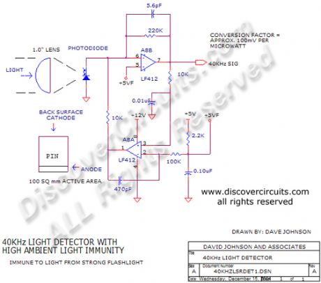
This circuit is designed for detecting infrared light modulated at around 40KHz. Its feedback scheme cancels much of the DC component from ambient light. It?s conversion factor is about 100 millivolts per microwatt of 900nm light.
Source: discovercircuits (View)
View full Circuit Diagram | Comments | Reading(0)
Low Value Capacitance Meter
Published:2012/9/6 20:01:00 Author:Ecco | Keyword: Low Value, Capacitance Meter
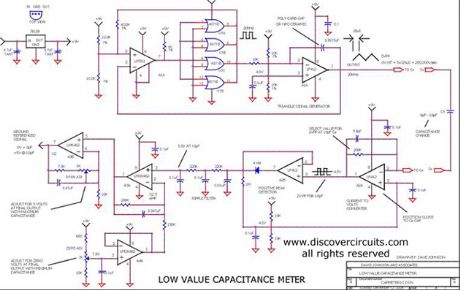
This circuit was originally designed to measure the volume of fluid inside a medical syringe. As designed, it produces a zero to 5 volt output, corresponding to a capacitance change of about 10 picofarads. With a digital voltmeter, at its output, it can resolve a capacitance change of 0.002 picofarads or 2 femtofarads.
Source: discovercircuits (View)
View full Circuit Diagram | Comments | Reading(0)
125KHz Wireless Smart Key Detector
Published:2012/9/5 20:57:00 Author:Ecco | Keyword: 125KHz, Wireless, Smart Key, Detector

This circuit will turn on an indicator light whenever it detects a smart car key containing an RFID chip.
Source: discovercircuits (View)
View full Circuit Diagram | Comments | Reading(3692)
Solar PV cell Test Fixture
Published:2012/9/5 20:45:00 Author:Ecco | Keyword: Solar, PV cell, Test Fixture
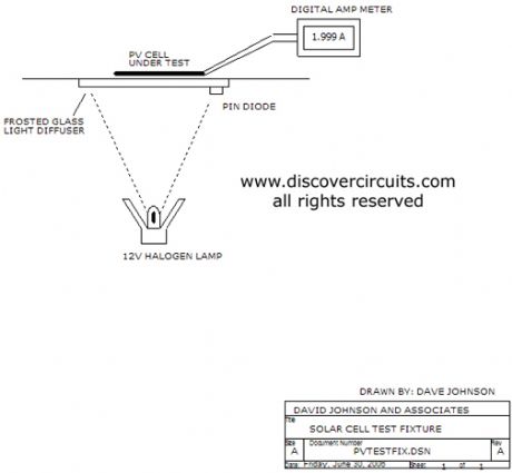
This is an illustration of a test fixture, which can be used to test individual solar cells for short circuit current. Using a PIN photo diode and a control circuit, the solar cells can be tested under constant light level conditions. A halogen incandescent lamp is used as the light source
Source: discovercircuits
(View)
View full Circuit Diagram | Comments | Reading(904)
4-20ma Current Loop Tester
Published:2012/9/5 20:36:00 Author:Ecco | Keyword: 4-20ma, Current Loop , Tester
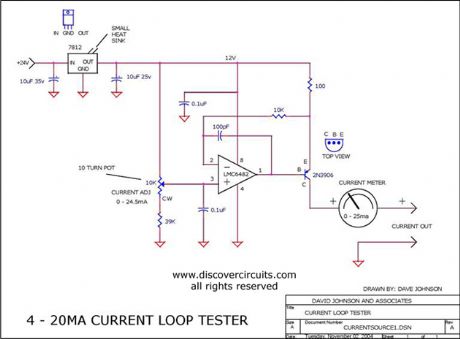
This circuit injects an adjustable current through a wire loop. Using a digital current meter, the current can be adjusted from near zero to over 24 milliamps.
Source: discovercircuits (View)
View full Circuit Diagram | Comments | Reading(7637)
XENON LAMP FLASH DETECTOR
Published:2012/9/5 20:33:00 Author:Ecco | Keyword: XENON LAMP FLASH, DETECTOR

This circuit uses a small 2.5mm square photo diode in conjunction with a 100mH coil to detect the short light flashes from a xenon lamp. The coil makes the circuit immune to normal room lights. Its 10mv sensitivity can detect light flashes from a range of over 100 feet. Reflections from a room?s walls and ceiling is usually enough to trigger the circuit. The entire circuit draws only 3 Microamps from a 6 to 9 volt battery.
Source: discovercircuits (View)
View full Circuit Diagram | Comments | Reading(9)
WIDE BAND ZERO CROSS DETECTOR
Published:2012/9/5 20:22:00 Author:Ecco | Keyword: WIDE BAND, ZERO CROSS, DETECTOR
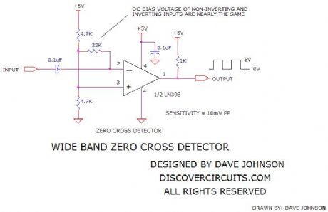
This circuit was designed to convert a low amplitude 40KHz signal into a clean square wave signal. It will work with inputs as small as 5mv peak-to-peak or as large as 3 volts peak to peak. The input frequency can range from a few kilohertz to about 150KHz.
Source: discovercircuits (View)
View full Circuit Diagram | Comments | Reading(0)
PRECISION AC PEAK DETECTOR
Published:2012/9/5 20:22:00 Author:Ecco | Keyword: PRECISION , AC PEAK , DETECTOR
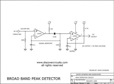
This unique circuit uses a very inexpensive voltage comparator to form a peak detector. The DC voltage produced tracks the positive peak of the input signal. It works from about ten millivolts to about 10 volts peak to peak. The maximum frequency is about 150KHz.
Source: discovercircuits (View)
View full Circuit Diagram | Comments | Reading(7)
Button Battery Cell Internal Resistance Measurement Circuit
Published:2012/9/4 20:32:00 Author:Ecco | Keyword: Button , Battery Cell, Internal Resistance , Measurement Circuit
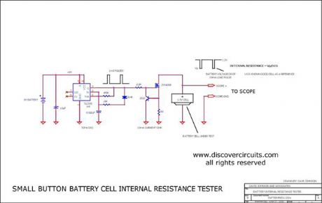
The open cell voltage of a small silver oxide button cell battery remains very close to 1.5 volts over most of the life of the cell. However, there is a relationship between battery health and the internal resistance of the cell. This circuit when used in conjunction with an oscilloscope will measure the internal resistance. You will have to use a known good cell as a reference.
Source: discovercircuits (View)
View full Circuit Diagram | Comments | Reading(3000)
6V NiCd/NMH Battery Test Circuit - 10 Amp Constant Current Load
Published:2012/9/4 20:32:00 Author:Ecco | Keyword: 6V, NiCd/NMH Battery, Test Circuit, 10 Amp , Constant Current Load
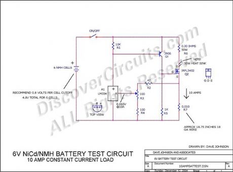
I designed this circuit to test rechargeable six volt battery packs under constant current conditions. As designed, the circuit applies a 10 amp load to the battery pack. A heat sink must be used on the main power transistor.
Source: discovercircuits (View)
View full Circuit Diagram | Comments | Reading(1736)
Logarithmic Light Intensity Meter for Photography
Published:2012/9/3 3:12:00 Author:Ecco | Keyword: Logarithmic, Light Intensity Meter, Photography
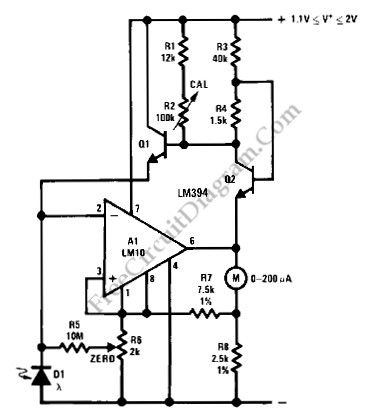
Using LM10 amplifier and voltage reference, a light intensity meter featured with five decades dynamic range (which is suitable for photographic application) can be built. Please note that the linear to log conversion is not temperature compensated, and can make 40% error (a half stop in photography) at the worst point of conversion slope at ±18°C temperature drift. It should be noted that silicon photodiode is sensitive to near-infrared wavelength, while ordinary films are not. Filtering out the infrared using infrared-stop filter or using blue-enhanced photodiode will improve the performance.(Source: freecircuitdiagram)
(View)
View full Circuit Diagram | Comments | Reading(1168)
Celsius thermometer circuit diagram with AD594
Published:2012/8/29 21:18:00 Author:Ecco | Keyword: Celsius thermometer

AD594/595 can also be configured to the Celsius thermometer, and the circuit is shown as the figure. The IN + and IN - ends should be connected with COM in short circuit, the temperature coefficient of the output voltage Uo is 10mV / ℃, and it can be served in the DVM to measure and display the temperature value.
(View)
View full Circuit Diagram | Comments | Reading(1667)
Accurate peak-valley value detector circuit
Published:2012/8/28 2:13:00 Author:Ecco | Keyword: Accurate , peak-valley value , detector
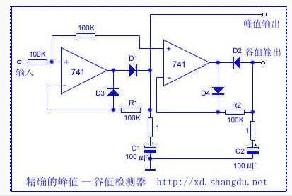
This circuit only uses two operational amplifiers to complete the peak-valley value detection of non-sine waveform. During the peak period, D1 breakover makes the C1 charge and reach peak, because of limiting effect of R1, C1 discharge minimal, charge again until the next peak to maintain the peak voltage output. Valley detection is contrary to the above values. C2 rapidly discharges to Valley value voltage by D2 during valley and trace discharges while other time only by D4, R2; C2 always remains valley voltage. The 1 Ω resistor connected to C1, C2 in series is used to prevent overshoot.
(View)
View full Circuit Diagram | Comments | Reading(3280)
The accelerometer circuit with monolithic acceleration sensor MMA1220D
Published:2012/8/27 1:44:00 Author:Ecco | Keyword: accelerometer , monolithic acceleration sensor
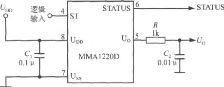
C1 is the power supply decoupling capacitor. R and C2 form a low-pass filter to filter out the switching capacitor to generate noise. Whenpin 4 inputs high, thechip reset.
(View)
View full Circuit Diagram | Comments | Reading(999)
Pipe pressure monitoring circuit with MPX4100A integrated Silicon pressure sensor
Published:2012/8/27 1:23:00 Author:Ecco | Keyword: Pipe pressure , monitoring circuit , integrated Silicon , pressure sensor
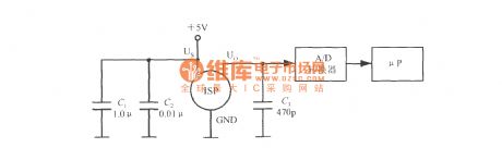
The typical application circuit of MPX4100A is shown in the figure, MPX4100A is used to monitor pipeline pressure. It uses the +5 V power supply, C1 and C2 are the power supply decoupling capacitors. C3 is the denoising capacitor of the output end. Integrated silicon pressure sensor output voltage (ISP) is first converted the digital by the A / D converter, and then sent to the microprocessor (μP) to calculate the measured pressure value. In order to simplify the circuit, it also can use microcontroller with A / D converter such as the Motorola company's MC68HC05 microcontroller.
(View)
View full Circuit Diagram | Comments | Reading(1139)
White luminance measuring circuit composed of visible brightness sensor LX1970
Published:2012/8/26 22:44:00 Author:Ecco | Keyword: White luminance, measuring circuit, visible brightness sensor
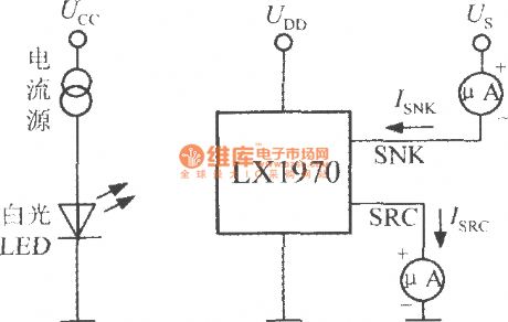
UCC, current source and white-light LED form thelight sources which can emit visible light, and thevisible light isreceivedand transformed into a current signal by the LX1970. The SNK port, SRC port arerespectively connected with a micro-table in series to measure optical flowing ISNK, ISRC, and micro-table reading value reflects the level of brightness.
(View)
View full Circuit Diagram | Comments | Reading(1046)
| Pages:22/101 At 202122232425262728293031323334353637383940Under 20 |
Circuit Categories
power supply circuit
Amplifier Circuit
Basic Circuit
LED and Light Circuit
Sensor Circuit
Signal Processing
Electrical Equipment Circuit
Control Circuit
Remote Control Circuit
A/D-D/A Converter Circuit
Audio Circuit
Measuring and Test Circuit
Communication Circuit
Computer-Related Circuit
555 Circuit
Automotive Circuit
Repairing Circuit