
Measuring and Test Circuit
Index 30
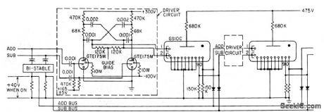
CURRENT_AMPLITUDE_DETECTOR
Published:2009/7/14 4:32:00 Author:May
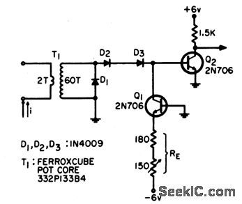
Used to indicate when pulsed drive currents for memory array exceed tolerance limits. Can detect current pulse deviation of 10 ma from 1.2-amp current Amplitude Detector, EEE.12:11,p68-70 . (View)
View full Circuit Diagram | Comments | Reading(1040)
OPAMP_DC_VOLTMETER
Published:2009/7/15 3:01:00 Author:Jessie
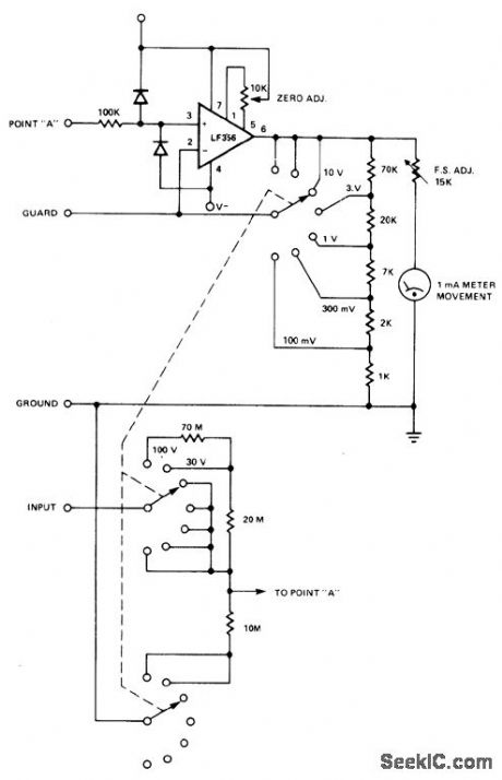
Uses LF356 opamp in noninverting connection to give high input impedance along with diode protection against input overvoltage. On 100-V range, input impedance is 100 megohms. - Signetics, Analog Data Manual, Signetics, Sunnyvale, CA, 1977, p 640-641. (View)
View full Circuit Diagram | Comments | Reading(1135)
OPAMP_ELECTROMETER
Published:2009/7/15 3:32:00 Author:Jessie
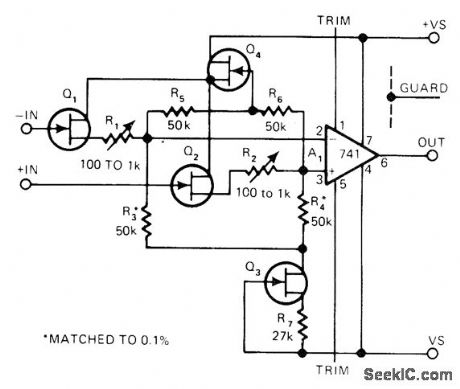
Use of FET input keeps input bias current down to 20 femtoamperes, with common-mode input resistance of 1015 ohms. Uses Analog Devices AD 832 dual JFET Q1-Q2 in source-follower connection, with low-cost general-purpose AD 3958 dual FET generating operating current and providing bootstrapping for Q1-Q2. Article covers guarding techniques used to minimize leakage currents.-J. Dostal, Electrometer Boasts Low Bias Current, EDN Magazine, Jan. 20, 1977, p 90 and 92. (View)
View full Circuit Diagram | Comments | Reading(3369)
7_DIGIT_BINARY_COUNTER
Published:2009/7/14 4:19:00 Author:May
Stores pulses re calved from oscillator gate. 128th pulse resets counter to zero. Complete binary counter consists of seven cascaded bistable multivibrators, transformer-triggered.-W. W. Grannemann et al, Pulse-Height-to-Digital Signal Converter, Electronics, 33:2, p 58-60. (View)
View full Circuit Diagram | Comments | Reading(1154)
FET_VOLTMETER
Published:2009/7/15 4:47:00 Author:Jessie

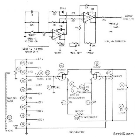
With FET in one leg of Wheatstone bridge, meter has input impedance of over 1 megohm. With no input voltage, adjust R4 so meter reads zero. With 9-V battery, RI can be adjusted for full-scale meter reading of 8 V. With 12-V battery, meter range is 0-10 V.-F. M. Mims, Transistor Projects, Vol. 2, Radio Shack, Fort Worth, TX, 1974, p 59-66. (View)
View full Circuit Diagram | Comments | Reading(0)
FLIP_FLIP_RING_COUNTER
Published:2009/7/14 4:09:00 Author:May
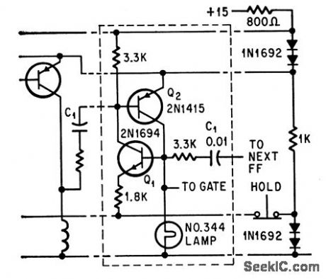
Complementary mvbr, in which Q1 and Q2 are either both on or both off, gives low power drain. Strong negative pulse applied to base of Q2 of first stage gives reset.-J. E. Russell, Ten Signals at a Glance, Electronics, 37:19, p 54-57. (View)
View full Circuit Diagram | Comments | Reading(843)
20_KC_RING_COUNTER
Published:2009/7/14 4:07:00 Author:May
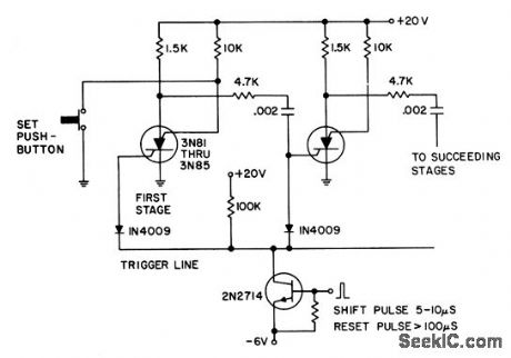
Shift pulses turns off conducting sillicon controlled switch by reverse-biasing cathode gate. Charge stored on coupling capacitor then triggers next gate.- Transistor Manual, Seventh Edition, General Electric Co. 1964, p 431. (View)
View full Circuit Diagram | Comments | Reading(940)
2SUP2_SUP_SUB3_SUB_DIGIT_VOLTMETER
Published:2009/7/15 4:41:00 Author:Jessie
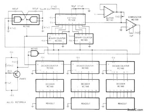
Closed-loop system designed around Motorola MC1408 8-bit D/A converter uses clocked binary counter feeding converter to produce staircase ramp function. output of converter is compared to unknown input signal, and clock pulse is terminated when levels being compared are equal. Clock pulses are generated at 330 kHz by two cross-coupled NAND gates in MC7400. UJT oscillator resets both sets of counters so unknown voltage is re-sampled every 0.5 s, MC7448 BCD to 7-segment decoders convert outputs of BCD counters to format for LED displays. With values shown, meter can measure up to 2.55Vin 10-mV steps. Different full-scale values can be obtained by using input voltage dividers or by replacing unity-gain input buffer with suitable fixed-gain buffer.-D. Aldridge, DAC Key to inexpensive22/3 Digit Voltmeter, Motorola, Phoenix, AZ, 1975, EB-21.
(View)
View full Circuit Diagram | Comments | Reading(1559)
1_kW_ON_2_METERS
Published:2009/7/14 3:49:00 Author:May
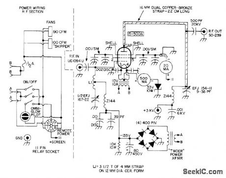
Developed for moonbounce communication. Article covers construction, with emphasis on insulation and cooling, and gives circuit of 3-kV power supply required.-R. W. Campbell, Kilowatt Linear Amplifier for 2 Meters, 73 Magazine, Dec. 1973, p 29-35. (View)
View full Circuit Diagram | Comments | Reading(1026)
PRECISION_RECTIFIER
Published:2009/7/15 4:22:00 Author:Jessie
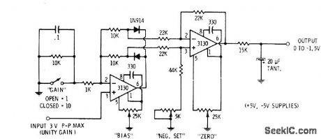
Used in digital voltmeters to convert AC waveform to full-waverectified DC equivalent. First 3130 opamp is used as polarity separator, with negative-going signals appearing across upper 10K resistor and positive-going signals across lower 10K resistor. Output of opamp exceeds these voltage drops by exactly diode voltage drop. Second opamp stage recombines positive and negative peaks. 5K trimming pot is adjusted so both peaks are equal height. Output of second opamp is negative-going full-wave replica of input signal. After filtering, output is average DC value in range from 0 to -1.5 V for 0-3 V P-P input.-D. Lancaster, CMOS Cookbook, Howard VV. Sams, Indianapolis, IN, 1977, p 345-346. (View)
View full Circuit Diagram | Comments | Reading(1840)
3SUP1_SUP_SUB2_SUB_DIGIT_DVM
Published:2009/7/15 4:13:00 Author:Jessie
Combination of National LF11300 dual-slope analog building block and MM74C928 CMOS 31/2-decade counter with 7-segment outputs gives automatic-zeroing automatic-polarity 31/2-digit digital voltmeter. Counter drives LED display with multiplexed 7-segment information under control of internal free-running oscillator. Interface circuits provide nonoverlapping control signals to LF11300 for polarity determination and offset correction for every conversion cycle. Analog circuit draws 1.5 mA from each 12.5-V battery. Digital circuit draws about 40 mA from 6-V supply.- CMOS Databook, National Semiconductor, Santa Clara, CA, 1977, p 5-36-5-37. (View)
View full Circuit Diagram | Comments | Reading(2569)
STRIP_CHART_TIMING_MARKS
Published:2009/7/15 4:10:00 Author:Jessie
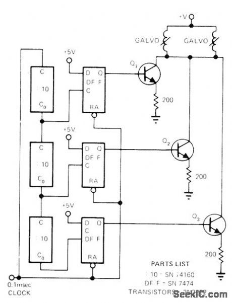
Drives two galvanometers for generating three decades of timing marks in identical patterns on edges of chart. 10-ms marks are twice as long as 1-ms marks, and 100-ms marks are 3 times length of 1-ms marks. By placing ruler across equivalent marks on edges, exact time for any point on recorded pattern is easily and accurately deter-mined.-S. Rummel, TTL Circuit Aids Evaluation of Oscillograph Data, EDN Magazine, Dec. 5, 1973, p 86. (View)
View full Circuit Diagram | Comments | Reading(1142)
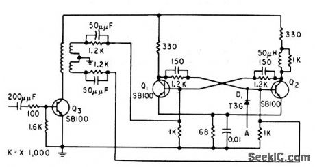
UNIJUNCIION_RING_COUNTER
Published:2009/7/14 3:56:00 Author:May
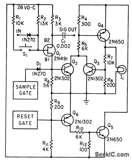
Provides switching for readout and control applications, including data display for airborne digital instrumentation. Q5-Q6 provide resetting.-F. W. Kear, Digital Control Uses Unijunction Transistors, Electronics, 34:18, p 79-80 (View)
View full Circuit Diagram | Comments | Reading(809)
BOXCAR_ENVELOPE_DETECTOR
Published:2009/7/15 4:06:00 Author:Jessie
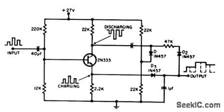
Gives accurate recovery of one-polarity modulation envelope by approximating envelope in level steps between successive peaks of wavetrain. -J. L. Markwalter. Boxcar Envelope Detector,EEE,12:9,p62-63. (View)
View full Circuit Diagram | Comments | Reading(913)
EIGHT_CHANNEL_COMPUTERIZED_3SUP1_SUP__SUB2_SUB_DIGIT_VM
Published:2009/7/15 4:04:00 Author:Jessie
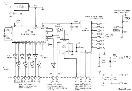
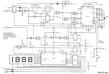
Displays up to eight different DC voltages on CRT terminal of microprocessor under key-board control, using BASIC commands and BASIC routine given in article. Uses Motorola MC14433 modified dual-lamp integrating analog-to-digital converter. Unknown voltage is applied to integrator having defined integration time constant for predetermined time limit, to give output voltage proportional to unknown voltage. Computer program substitutes -2,000 V reference from IC2, and circuit keeps track of time for integrator output to move back toward zero. Changing reference to 0.200 V makes same 1999 count represent 199.9 mV full scale. IC1 performs about 25 conversions per second. IC3 and IC4 are output buffers, IC5 is 7474 used as set-reset flip-flop. IC6 is eight-input CMOS multiplexer input.-S. Ciarcia, Try an 8 Channel DVM Cocktail!, BYTE, Dec. 1977, p 76, 78, 80, 92, 94, 96, and 98-103. (View)
View full Circuit Diagram | Comments | Reading(2086)
NULL_INDICATOR
Published:2009/7/15 3:59:00 Author:Jessie
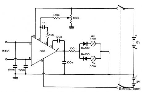
Opamp is driven open-loop so change of only 1 mV in input voltage makes output switch polarity. This is indicated by one of lamps. Both lamps go out to indicate null. If LEDs are used in place of lamps, diodes are not needed; adjust series resistance as required for full brilliance of LEDs.-B. P. Cowan, Miniature Null Indicator, Wireless World, June 1973, p 284.
(View)
View full Circuit Diagram | Comments | Reading(1029)
35_W_CLASS_D_ON_40_80_OR_160_m
Published:2009/7/14 3:41:00 Author:May
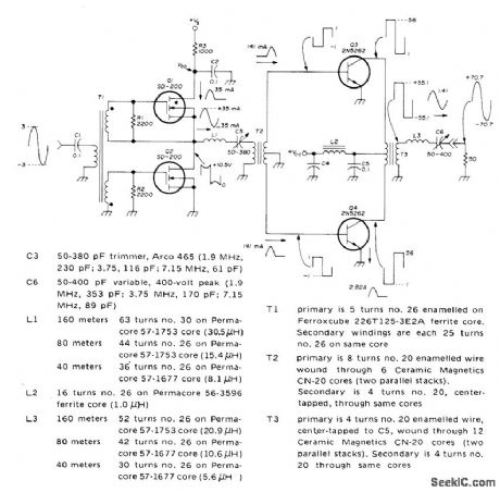
Can be used on any of three bands by changing values as set forth in parts table. Article gives circuit design procedure in detail. Power gain is about 27 dB. Almost any type of RF amplifier providing about 100 mW can be used as driver. VS is 25 V or less, and VCC, is 28 V.-F. H. Raab, High-Efficiency RF Power Amplifiers, Ham Radio, 0ct. 1974, p 8-29. (View)
View full Circuit Diagram | Comments | Reading(898)
0_2_V_DVM
Published:2009/7/15 3:53:00 Author:Jessie
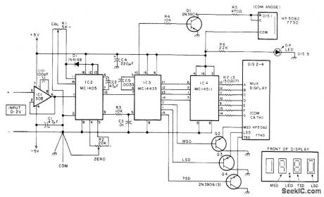
Uses three Motorola digital voltmeter ICs preceded by opamp having 10-meg-ohm input impedance, driving Hewlett-Packard HP5082 multiplexed digital display, with LED serving as decimal point. Input leads must be reversed to read negative voltages. Article gives construction and calibration details. Errata: move C3 upper connection to pin 9 of IC2, and transpose connections to pins 1 and 2 of IC3.-G. McClellan, DVMs Get Simpler and Simpler,73 Magazine, Feb. 1977, p 60-63.
(View)
View full Circuit Diagram | Comments | Reading(1853)
BIDIRECTIONAL_MULTIDECADE_COUNTER
Published:2009/7/14 1:51:00 Author:May
Single sign-determining circuit of input to tens stage provides gating signals for every decade, to handle rapid reversal of count direction.-L. C. Burnett, Reversible Decade Counter, Electronics, 35:9, p 46. (View)
View full Circuit Diagram | Comments | Reading(958)
DVM_POLARITY_INDICATOR
Published:2009/7/15 3:51:00 Author:Jessie
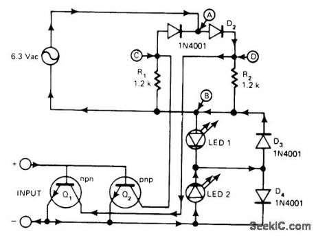
Designed for use in low-cost digital voltmeters. With input polarity as indicated, arrows on connections indicate direction of current flow. When NPN Q1 is on, LED 2 will be on; with PNP Q2 on, LED 1 will be on. Darlingtons Q1-Q2 draw very little current, so choice of type is not critical. AC supply is usually available in lab but can be replaced by internal clock of DVM driving small transformer to give required floating AC source, A, B, C, and D identify nodes of bridge.-R. A. Snyder, Polarity Indicator Minimizes Parts Count, EDN Magazine, Feb. 20, 1977, p 121. (View)
View full Circuit Diagram | Comments | Reading(1084)
| Pages:30/101 At 202122232425262728293031323334353637383940Under 20 |
Circuit Categories
power supply circuit
Amplifier Circuit
Basic Circuit
LED and Light Circuit
Sensor Circuit
Signal Processing
Electrical Equipment Circuit
Control Circuit
Remote Control Circuit
A/D-D/A Converter Circuit
Audio Circuit
Measuring and Test Circuit
Communication Circuit
Computer-Related Circuit
555 Circuit
Automotive Circuit
Repairing Circuit