
Measuring and Test Circuit
Index 33
GAS_TUBE_RING_COUNTER
Published:2009/7/13 23:33:00 Author:May
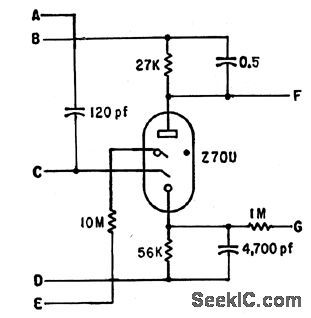
Uses Philips trigger tubes in decade counter having maximum speed of 2,500 pps Bias developed at cathode is fed through G to prime following stage Readout display can be Burroughs Nixie HBl06 or other numerical indicator.-P. G. Hodgson, Cold-Cathode Ring-Counter Drives Numerical Indicator, Electronics, 33:14, p 80. (View)
View full Circuit Diagram | Comments | Reading(923)
REVERSIBLE_TEN_SIAGE_RING_COUNTER
Published:2009/7/13 23:32:00 Author:May
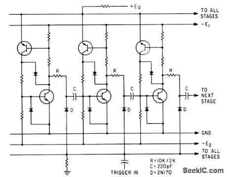
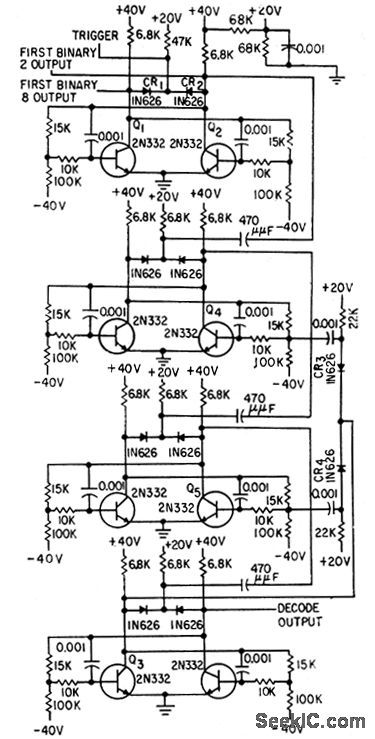
Can be operated above 100 kc. Reversible operation requires binary control, such as by bistable mvbr, to determine direction. Upper transistors are 2N414 and lower are 2N488.Other resistors are 1K.-N. C. Hekimian, PNP-NPN CIRCUITS: New Look at a Familiar Connection, Electronics, 35:47, p 42-46. (View)
View full Circuit Diagram | Comments | Reading(1054)
HIGH_SPEED_BCD_COUNTER
Published:2009/7/13 23:28:00 Author:May
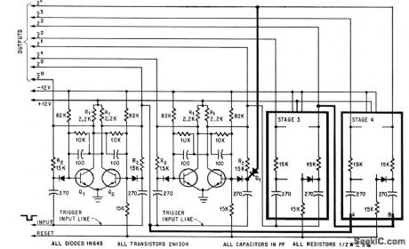
Elimination of capacitively coupled feedback increases operating speed to, maximum repetition rate of flip-flop stages. By modifying circuit as shown in heavy lines and adding diode D1, circuit returns to initial state at count of 10 rather than 16.-P. Ward. Modified Decade Counter Eliminates Components. Electronics.38:25,p74-75 (View)
View full Circuit Diagram | Comments | Reading(871)
DVM_CAPACITANCE_METER_ADAPTER
Published:2009/7/16 1:31:00 Author:Jessie
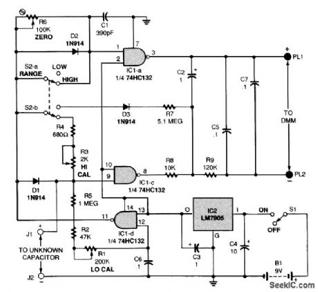
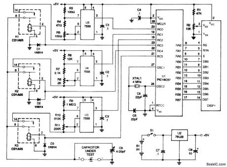
The figure shows the schematic for the capacitance meter adapter. When power switch S1 is in the ON position, an LM,7805 regulator (IC2) provides a 5-V source to the circuit. Switch 52 is used to select between the high- and low-capacitance ranges. The circuit measures from 0 to 2200 pF in its low range and from 0 to 2.2 μF in its high range. The adapter outputs 1 mV/pf in the lower range and 1 V/pF in the higher range. Those voltages would be displayed on a DMM, and would have to be read as capacitance values. Gate IC1-d is configured as a free-running oscillator whose frequency is determined by the setting of potentiometer R1. The output of IC1-d, pin 11, is a square-wave volt-age that is fed to the other two gates configured as inverters (IC1-a and IC1-c). A capacitor with an unknown value (CX) is connected across input terminals J1 and J2. Note that the positive lead of a polarized capacitor must be connected to J1. The capacitor under test charges through diode Dl on positive half cycles and discharges through R5 on negative half cycles in the low range, or through R3, R4, and R5 in the high range. In the high range, the square-wave output from IC1-d is fed directly to the inputs of the other two gates. With no capacitor connected to J1 and J2, the outputs of IC1-a and IC1-c are identical inverted versions of the input signal. The average voltage across the outputs of the gates at pins 3 and 8,In this case,is zero .With CX in place,and depending on its value,the input voltage to IC1-c,pin 9,stays higher longer than the input to IC1-a,pin 2.The output pulses from IC1-a and IC1-c are filtered and smoothed by R8,R9,C2,and C5 The average dc voltage across the outputs IS then proportional to the value of CX The circuit is a bit different in the low-range because compensation must be made for stray capacitance In the low range the output from IC1-d is fed to pin 1 of IC1-c through diode D2,which also charges C1 Capacitor C1 charges quickly and discharges slowly through potentiometer R6.The charge on C1 holds the input to IC1-a higher for a slightly longer time than would normally be the case That causes its inverted output to be low for a slightly longer time,and conversely high for a slightly shorter time Stray capacitance across input terminals J1 and J2 does the same thing to IC1-c,holding its input higher for a slightly longer time than would be the case f there were none Potentiometer R6 is adjusted so that the discharge time for C1 matches that of the stray capacitance and so cancels it out In the low range,an offset voltage is applied to the negative output terminal via D3,R7,and R8 to prevent the gates from locking together with such close trigger points (View)
View full Circuit Diagram | Comments | Reading(3191)
AUTO_RANGING_CAPACITANCE_METER
Published:2009/7/16 0:02:00 Author:Jessie
The schematic for the meter is shown. When switch S1 is closed, a 9-V battery, B1, supplies power to a 78L05 regulator, U2, and to filter capacitors C7 and C8. The result is a 5-Vdc supply for the rest of the circuit. Because the current draw is low, the 9-V battery will provide close to 40 1/2 hours of usage. A microchip PlC16C57, UI, is at the heart of the circuit. The internal EPROM is programmed with the meter's program. The circuit uses one of three 7555 CMOS timers, U3 to U5, to generate a pulse train. Microcontroller UI turns on one relay to connect the capacitor to one of the three timing circuits. The timer circuit, made up of U5, R3, R4, R5, and C1, has the lowest resistance and impedance; U4, with its surrounding components, has a medium resistance and impedance; and U3's circuit has the highest. All the timer circuits have two nominally equal resistors; one of them is the series combination of a fixed resistor and a trimmer potentiometer. That variable combination is for calibration. The high-impedance (1-MΩ) circuit is the default and is used for small-valued capacitors, the medium-impedance (10,000-Ω) circuit is used for medium-valued capacitors, and the low impedance (100-Ω) circuit is used for high-valued capacitors. When the capacitor under test is connected to the appropriate circuit, the microcontroller measures the frequency. A 4-MHz crystal, XTAL1, gives UI a 1-MHz internal clock frequency. The microcontroller can, therefore, count the number of pulses from the appropriate timer circuit in a known period of time. It then goes on to convert the frequency to capacitance using 32-bit, floating-point arithmetic, and displays the results on a 16×1 LLCD, DISP1, with the correct unit and decimal point. Capacitor C9 is connected in parallel to the capacitor under test to aid in final calibration and for stability. Diodes D1 to D3 protect the microprocessor from the back EMF of the relays' coils. Before you can use the PIC microprocessor in the meter, you have to program it. If you have the equipment to do that, you can obtain the software from the Gernsback BBS (516-293-2238). (View)
View full Circuit Diagram | Comments | Reading(2538)
SIMPLE_CAPACITY_METER
Published:2009/7/15 23:55:00 Author:Jessie
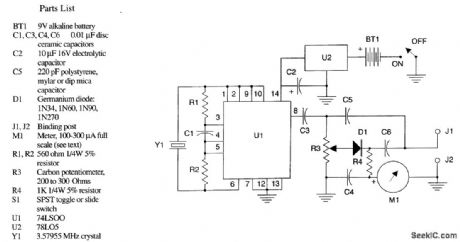
The figure shows the schematic diagram of the simple capacity meter. U1 (a 74LSOO logic chip), two resistors, a capacitor, and a crystal form a crystal oscillator operating near the marked frequency of the crystal. The RI' voltage is taken from pin 8 through isolation capacitor C3 and applied to the modified Wheatstone bridge circuit. R3 forms two arms of the bridge, with the arms ratio variable through the position of the wiper of R2. C5, which should be the stable capacitor specified in the parts list, and the unknown capacitor to be measured form the remaining bridge arms. R3 is adjusted for bridge balance, indicated by a dip minimum shown on microammeter M1, and the value of the un-known capacitor is indicated on the calibrated dial attached to R3. The instrument is powered by BT1, a 9-V battery, controlled by on/off switch S1. This 9 V is reduced and regulated by U2, a 78LO5, to the +5 V required by U1. (View)
View full Circuit Diagram | Comments | Reading(1996)
SCANNER_FOR_2_METERS
Published:2009/7/13 23:15:00 Author:May

Developed for use with frequency synthesizer to scan transmit and receive frequencies of four receivers plus six other channels in 2-meter amateur band. Pin connections at left go to socket provided on lcom IC-230 synthesizer for connecting external VFO operating between 11.255 and 12.255 MHz. Q1-Q10can be 2N3638 or equivalent; Q11 is any NPN silicon such as 2N2102; and Q12 is 2N2102. LEDs operate from +12 V. In operation, scanner stops on active channel, and resumes scanning 5 s after channel goes off air. Article covers circuit operation, gives construction details, and tells how to calculate crystal frequency for each channel desired.-C. A. Kollar, Two Meter Scanner, 73 Magazine, June 1977, p46-48.
(View)
View full Circuit Diagram | Comments | Reading(1873)
HIGH_RESOLUTION_BRIDGE
Published:2009/7/15 23:49:00 Author:Jessie
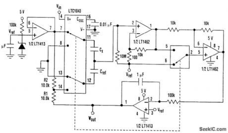
A JFET-input op amp (LT1462) amplifies the signal before demodulation for good noise performance, and the integrator's output is attenuated by RI and R2 to increase the sensitivity of the circuit. If △CX<<CX and Cref≈CX then
Vout-Vref≈Vref(△CX/Cref)[(R1+R2)/R2]
With Cref 50 pF, the circuit has a gain of 5 V/pF and can resolve 2 fF. Supply current is 1mA. The synchronous detection makes this circuit insensitive to external noise sources; in this respect, shielding isn't terribly important. However, to achieve high resolution and stability, care should be taken to shield the capacitors being measured. Bridge circuits are particularly suited for differential measurements. When CX, and Cref are replaced with two sensing capacitors, these circuits measure differential capacitance changes, but reject common-mode changes. CMRR for the circuit in this figure exceeds 70 dB. In this case, however, the output is linear only for small relative capacitance changes (View)
View full Circuit Diagram | Comments | Reading(1132)
40000_CPS_DECADE_COUNTER
Published:2009/7/13 23:11:00 Author:May
Basic building block in counter is bistable mvbr which produces binary counts. Operates over wide range of operating voltages and temperatures.-Decade Counter is Flexible, Reliable, Electronics, 31:49, p 104-106. (View)
View full Circuit Diagram | Comments | Reading(891)
HYBRID_RING_COUNTER
Published:2009/7/13 23:10:00 Author:May

Counts reliably up to about 500 kc, with trigger amplitude of 4.5V All stages are identical.-G. A. Dunn and N.C. Hekimian. Tube-Transistor Hybrids Prove Design Economy. Electronics.32:23,p68-70. (View)
View full Circuit Diagram | Comments | Reading(825)
CABLE_REFLECTION_TESTER
Published:2009/7/15 23:40:00 Author:Jessie
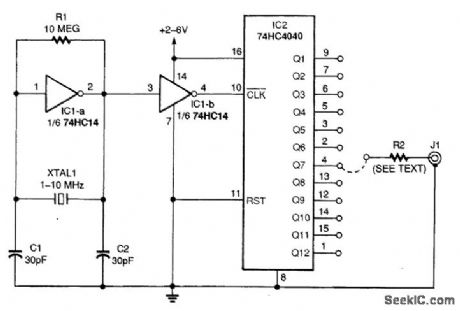
This device is a square-wave generator and frequency divider. A square-wave generator supplies a signal to the cable through a resistance (R2) equal to the characteristic impedance of the cable. Any reflections caused by mistermination will show up on a scope hooked to J1. IC2 acts as a frequency divider to produce various pulse rates for testing long and short cable. (View)
View full Circuit Diagram | Comments | Reading(1806)
MULTICONDUCTOR_SHORT_OPEN_CABLE_TESTER
Published:2009/7/15 23:38:00 Author:Jessie
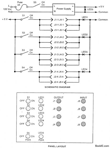
Frequent or regular testing of multiconductor cables terminated in multipin conductors can be a tedious, if not impossible, task. This is especially true if the cables must be tested for both open and short circuits for all of the various combinations of conductors. The inexpensive circuit shown in the figure simplifies the task. In operation, a pair of connectors is selected to match the pair of connec-tors installed on each of the cables to be tested. A single-pole/single-throw (SPST) toggle switch is provided for each conductor of whichever cable in the system has the greatest number of conductors. One conductor of each of the output connectors is connected in parallel to the anode of an LED.One LED is required for each conductor of the cable that has the greatest number of conductors. The cathodes of the LEDs are tied together and connected to the common side of the 5-V power supply.At the beginning of a test, all of the switches are turned off. First, one turns on power switch S5 and verifies that LED5 illuminates. Then one turns on switches S1 through S4, one at a time. Only the LED corresponding to the switch that is on should illuminate. An open conductor in the test cable is indicated if the corresponding LED is not illuminated. A short circuit is indicated if any other than the corresponding LED is illuminated. (View)
View full Circuit Diagram | Comments | Reading(1110)
CABLE_SHORT_DETECTOR
Published:2009/7/15 23:34:00 Author:Jessie
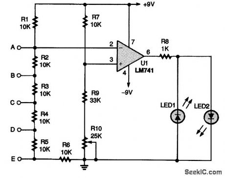
A five-input short-detector circuit can be used to check long runs of a two- to five-wire cable for shorts between any of the wires. An LM741 op-amp IC, U1, is connected in a comparator circuit. The inverting input (pin 2) of U1 is connected to a +9-V source and a series of six resistors, while the noninverting input (pin 3) of the op amp is connected to an adjustable voltage-divider circuit. To use the circuit, potentiometer R10 should be used to set the voltage at pin 3 to a slightly more negative voltage than that at pin 2; U1's output will swing low, lighting LED1. Make that adjustment slowly until LED1 just barely turns on. Then connect one end of a cable to points A to E. When any of resistors R2 to R6 are shorted out, the voltage at pin 2 will go negative with respect to pin 3. That will make the op amp's output go positive, which will light LED2, indicating a short in the cable. (View)
View full Circuit Diagram | Comments | Reading(2513)
CABLE_TESTER_RECEIVER
Published:2009/7/15 23:31:00 Author:Jessie
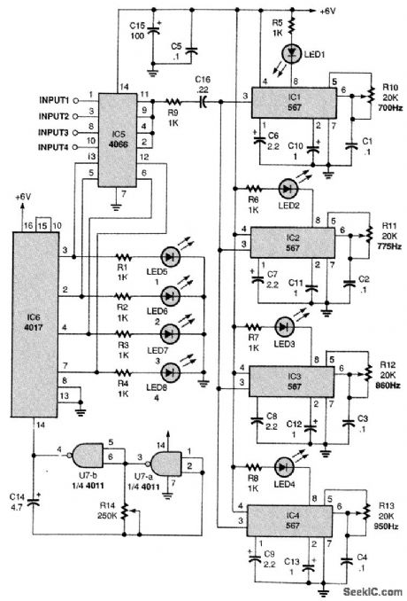
The four inputs are connected to four input contacts of a quad bilateral switch, IC5, with the out-put contacts tied together and connected to the inputs of the 567 decoders through R9 and C16. The bilateral switch's four control inputs are operated by IC6, a 4017 decade counter IC, which is driven by a low-frequency oscillator made up of two gates of IC7, a quad two-input NAND gate. Four LEDs, LED 5 through LED8, are connected to IC6's four outputs and indicate which input is being checked, just as in manual mode. When LED5 is on, input 1 is switched through to the four decoder circuits. The decoder that responds, by lighting its LED, indicates which output-700, 775, 880, or 950 Hz-is connected to that input. Resistor R14 sets the input-stepping rate, which should be slow enough for recording. (View)
View full Circuit Diagram | Comments | Reading(1335)
500_kHz_SCAN_ON_2_METERS
Published:2009/7/13 22:52:00 Author:May
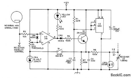
Circuit added to 2-meter transceiver sweeps 500-kHz segment of 2-meter band at 2-s intervals. When incoming signal is strong enough to trip receiver squelch, sweep stops and receiver locks on station. R4 and C3 determine scan rate. Adjust R1 for best lock-on. When signal is sensed, squelch is greater than 9 V on R3, driving output of U2 low, turning on LED, and removing charging voltage from R4. When signal disappears, output of U2 goes high and scanning continues.-W. Sward, Add Frequency Scan to a Receiver for $10, QST, March 1977, p 48. (View)
View full Circuit Diagram | Comments | Reading(1917)
LOGAMP_TESTER
Published:2009/7/13 22:34:00 Author:May
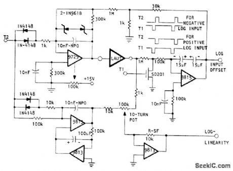
Circuit sweeps logamp under test (LAUT) over its dynamic range while automatically canceling offset voltage at input, with output serving as indication of this offset voltage. Exponential deeay voltage generated is accurate from 10 V to 100 μV. At time zero, pulse T2 is applied to Optical Electronics 9729 opamp connected as exponential generator, charging NPO feedback capacitor to 10V. At end of pulse, opamp output voltage decays exponentially. Input pulse also generates ±10 V precision reference ramp in pair of 9813 opamps. Output of LAUT is compared with reference ramp; any difference is proportional to nonlinearity of logamp.- Testing Logarithmic Amplifiers, Optical Electronics, Tucson, AZ, Tech Tip 10268. (View)
View full Circuit Diagram | Comments | Reading(839)
BIQUINARY_COUNTER_WITH_READOUT
Published:2009/7/13 22:13:00 Author:May
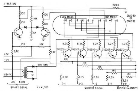
Simplified driver circuits require only seven transistor rather ten, when used with special Amperex ZMl032 tube.-Biquinary Indicator Uses 7 Transistors, Electronics, 36:28, p58.
(View)
View full Circuit Diagram | Comments | Reading(1083)
ALL_CHANNEL_VFO_FOR_2_METERS
Published:2009/7/13 22:04:00 Author:May
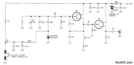
Permits coverage of all channels with ordinary FM transceiver without costly frequency synthesizer or individual channel crystals. Can also be used for tuning input of repeater when made necessary by malicious or accidental interference. Replaces first crystal oscillator in FM transceiver and tunes over required range, generally onethird of first injection frequency. Operates at about 45 MHz for most transceivers, but frequency can easily be changed. Tuning pot (10-turn 5K with digital dial is best) can be placed remotely. VFO uses FET oscillator tuned by tuning diode (also known as Varicap, varactor, or variable-capacitance diode). Source-follower output stage buffers oscillator. Supply is regulated by zener. Q1 and Q2 can be MPF102 FETs, but 2N5668 or 2N5669 are better. L1 is 4 turns No. 16 1/2 inch in diameter. Article covers construction, testing, and installation in transceiver.-P. Franson, Simple Tunable Receiver Modification for VHF FM, Ham Radio, Oct. 1974, p 40-43. (View)
View full Circuit Diagram | Comments | Reading(1296)
MULTIJUNCTION_SEMICONDUCTOR_AS_DECADE_COUNTER
Published:2009/7/13 21:56:00 Author:May
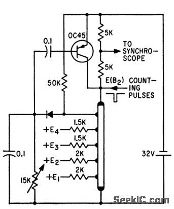
Experimental equivalent of cold-cathode counter tube, developed in Poland, cam serve also as staircase wave form generator. Although circuit shown, with five gm junctions on one side of n-type semi-conductor bur, gives only count of five before transistor restores initial state, decade counter would have ten junctions on bar.-A. Ambroziak, Semiconductor Analog of a Cold-Cathode Counter Tube, Electronics, 35:6, p 46-47. (View)
View full Circuit Diagram | Comments | Reading(1306)
WHEATSTONE_RESISTANCE_BRIDGE
Published:2009/7/16 2:32:00 Author:Jessie

R7 is a calibrated potentiometer. At null, RX equal Rn(R7/R6),where Rn=R1,R2,R3,R4,or R5,as selected by switch S1. (View)
View full Circuit Diagram | Comments | Reading(925)
| Pages:33/101 At 202122232425262728293031323334353637383940Under 20 |
Circuit Categories
power supply circuit
Amplifier Circuit
Basic Circuit
LED and Light Circuit
Sensor Circuit
Signal Processing
Electrical Equipment Circuit
Control Circuit
Remote Control Circuit
A/D-D/A Converter Circuit
Audio Circuit
Measuring and Test Circuit
Communication Circuit
Computer-Related Circuit
555 Circuit
Automotive Circuit
Repairing Circuit