
Measuring and Test Circuit
Index 28
LED_VOLTAGE_MONITOR
Published:2009/7/14 21:29:00 Author:May
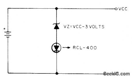
Uses Litronix RCL400 current-controlled LED having built-in voltage-sensing IC that turns on LED at 3 V and turns it off at 2 V. Use suitable zener or string of forward-biased silicon diodes to make VZ equal to 3 V less that VCC. Thus, for 4.5-V battery, put two silicon diodes in series with LED to make VZ 1.5 V across them.-S, W. Hawk-inson, A Battery Voltage Monitor, 73 Magazine, July 1977, p 52.
(View)
View full Circuit Diagram | Comments | Reading(998)
ULTRASONIC_MOTION_DETECTOR
Published:2009/7/14 21:16:00 Author:May
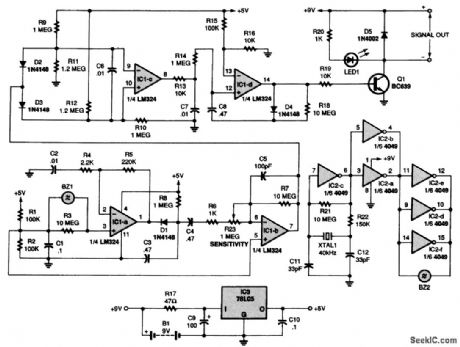
The receiver section of the circuit is made up of four ac-coupled stages, each built around one of four sections of an LM324 op amp, IC1. At the input to the third stage-a differential amplifier built around IC1-c-are two diodes, D2 and D3. They detect both positive and negative pulses. When there is no movement, the voltage at pin 7 of IC1-b is half the supply voltage and neither D2 or D3 can conduct. The voltage at pin 8 of IC1-c is then low. If the signal rises above +0.7 V, D3 conducts, causing the output on pin 8 to go high. If the signal falls below -0.7 V, D2 conducts, which also causes the output to go high. The fourth stage, built around IC1-d, is set up as a monostable flip-flop. That stage converts any signal that gets through the filter into a pulse substantial enough to turn on transistor Q1. When Q1 conducts, LED1 turns on and an output signal is provided to drive a separate relay or any other device connected to the circuit (View)
View full Circuit Diagram | Comments | Reading(0)
BAR_GRAPH_READOUT_VOLTMETER
Published:2009/7/14 23:38:00 Author:Jessie
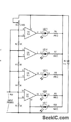
Sections of RS339 quad comparator each drive LED to give indications of four different input voltage levels, While LED 1 is connected to ground for use as zero indicator Resistors shown are for Radio Shack 276-041 red LEDs;change R6-R9 to 270 ohms and R1 to 470 ohms for green LEDs Pot R1 is used to calibrate voltage divider R2-R5 With R1 set allow resistance, comparators turn on at intervals of 1 V or more,With high resistance for R1, comparators turn on at fractional-volt intervals. –F. M. Mims,” Integrated Circuit Projects, vol. 4,” Radio Shack, Fort Worth, TX, 1977, 2 nd Ed., ρ76-85. (View)
View full Circuit Diagram | Comments | Reading(1301)
1_TERAOHM_INPUT
Published:2009/7/14 23:36:00 Author:Jessie
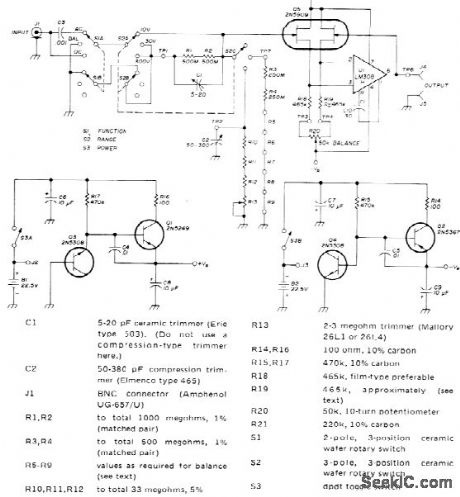
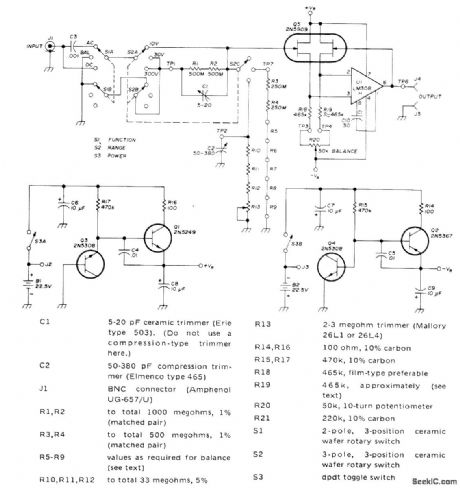
High-accuracy meter-interface amplifier for AC and DC voltage measurements has input resistance of 1,000,000 megohms. Amplifier eliminates voltmeter errors due to loading by using special 2N5909 dual FET with exceptionally low gate leakage current. FET and opamp are connected as voltage follower with gain of 1. Accuracy on 0-10 V range is 0.1% or better. For higher voltage ranges, accuracy depends on that of resistive voltage divider used. Three ranges provided have full-scale values of 10, 30, and 300 V. AC RMS inputs are limited to 70% of DC ranges. Two voltage regulators are used with battery supply to permit use of batteries exceeding 18-V voltage rating of opamp, so battery voltages can drop considerably before replacement is required. Article covers construction and adjustment.-J. R. Laughlin, High-Impedance Meter Interface, Ham Radio, Jan. 1974, p 20-25. (View)
View full Circuit Diagram | Comments | Reading(2951)
12_V_MONITOR
Published:2009/7/14 20:52:00 Author:May
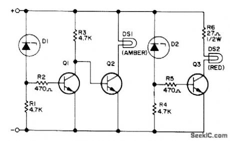
Voltage-limit sensor gives visual indication that voltage in auto or boat electric system is satisfactory for operation of critical electronic equipment. Combination of zener diodes D1 and D2 acting with base-emitter voltage drops of Q1 and Q3 makes any voltage less than 13.5 V turn on amber No. 330 pilot lamp (14 V at 80 mA), while voltage above 15.2 V turns on red pilot lamp of same type. Transistors are Motorola MPS 3704. D1is 1N5243B 13V zener, and D2 is 1N5245B 15-V zener.-M. J. Moss, Voltage Limit Sensor, 73Magazine, May 1973, p 53-54. (View)
View full Circuit Diagram | Comments | Reading(1027)
FLIP_FLOP_FOLLOWER_FOR_COUNTER
Published:2009/7/14 20:43:00 Author:May
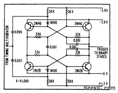
Used to count down cycles of timing mvbr. Output of flip-flop follower is used in and circuit with matrix gates to turn on tone-burst oscillators or multivibrators during positive half-cycles only.-R. W. Rochelle, Cyclops Cores Simplify Earth-Satellite Circuits, Electronics, 31:9, 56-63. (View)
View full Circuit Diagram | Comments | Reading(1255)
4SUP1_SUP_SUB2_SUB_DIGIT_VOLTOHMMETER
Published:2009/7/15 1:47:00 Author:Jessie

National type MM5330 IC provides logic circuits for implementing low-cost 41/2-digit voltohmmeter. Display interface consists of TTL 7-segment decoder driver and four 2N4403 transistors. Operation is based on counting of up to 80,000 clock pulses. Circuit provides sign digit, either plus or minus, and numeral 1 for 10,000 to give full display of ±19,999 with decimal point.- MOS/LSI Databook, National Semiconductor, Santa Clara, CA, 1977, p 5-23-5-29. (View)
View full Circuit Diagram | Comments | Reading(1626)
SIMPLE_VERY_LONG_PERIOD_TIMER
Published:2009/7/14 19:43:00 Author:May
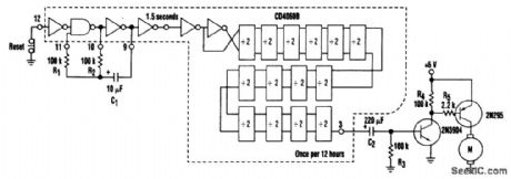
This circuit is straightforward. An RC oscillator consisting of R1, R2, and C1, with the internal gates on the CD4060, generates a 1.5-second clock that is subsequently divided to a 12-h clock at the output. Other times are available for output or for AND-ing with the longer-duration signals. The output is capacitively coupled to the two-transistor driver to provide a several-second pulse every 12 hours. (View)
View full Circuit Diagram | Comments | Reading(1735)
LINE_VOLTAGE_MONITOR
Published:2009/7/15 1:39:00 Author:Jessie
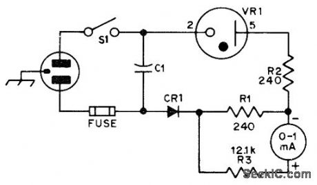
OC3 (VR-105) voltage-regulator tube provides voltage offset that permits greater sensitivity in voltage range of interest Meter scale covers 20-V range centered on about 115VAC,Accuracyismuch better than with AC range of ordinary multimeter,CE1 is 500-PlV 1-A silicon diode.-N Johnson, An AC Line Monitor, QST, Jan,1976, p 27. (View)
View full Circuit Diagram | Comments | Reading(0)
APPLIANCE_TIMER
Published:2009/7/14 19:37:00 Author:May
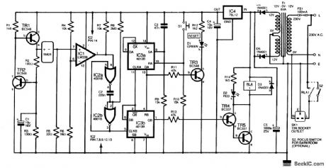
This design uses a low-cost digital kitchen timer to control appliances. No modification to the timer is needed; the only requirement is that it must beep both when the Start button is pressed crud when the period has expired. This appliance timer detects the supply current flowing through the timer, and drives an external relay circuit, which operates loads for a period set by the kitchen timer. A low-voltage supply is formed by transistors TR1 and TR2, a ring-of-2 constant-current source adapted to pro-vide about 1.5 V at the TR1 emitter (e). This powers the timer. At power on, capacitor C3 provides a positive pulse, which sets IC3a (pin 8), one-half of a dual D-type flip-flop. Output QA (pin 13) goes high, which resets IC3b, so that QB (pin1) is low. Transistors TR4 and TR5 are off,and so the relay RLA does not operate However, transistor TR3 is driven on and illuminates the green LED D1 to indicate reset The digital timer can now be set to the desired duration Then switch S1 is pressed which resets IC3a;QA goes low, which enables IC3b When the timer’s Start button is pressed,the Increase in its supply current caused by the beep rises from a few microamperes to 5 mA or more The voltage across resistor R5 rises,and comparator IC1,whose threshold is set by resistors R4 and R5 will output a brief positive pulse This is cleaned up by the monostable formed from IC2a and IC2b,and clocks IC3b Output QB(pin 1) now goes high and powers the relay via the Darlington transistor pair At the end of the period,the first beep clocks IC3b again Output QB(pin 2) goes high to clock IC3a(pin 11);QA goes high and resets IC3b so that the relay switches out. (View)
View full Circuit Diagram | Comments | Reading(0)
EXPANDED_RANGE_AC_VM
Published:2009/7/15 1:36:00 Author:Jessie
Line voltage is applied to D1, and resulting DC is filtered by C1 R1 delivers equivalent of RMS voltage to 100-V zener D2 through R2 Voltage is developed across R2 Only when voltage applied by R1 exceeds 100 V, for reading with 1000-ohm-per voltmeter To calibrate, rneasure AC line voltage with accurate AC Voltmeter, then adjust R1 so meter across R2 reads 100 V less than this value-W. P. Turner, Expanded Range Line Voltage Meter, 73 Magazine.March 1974, p 54. (View)
View full Circuit Diagram | Comments | Reading(880)
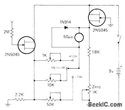
FET_MILLIVOLTMETER
Published:2009/7/15 1:34:00 Author:Jessie
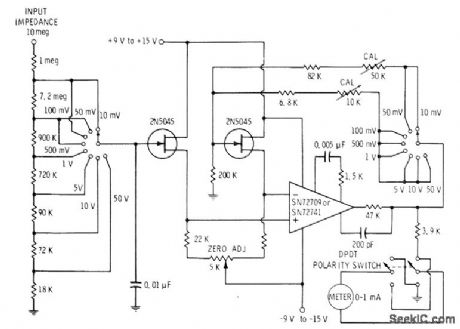
Eight-range meter uses pair of JFETs in bridge arlangement driving meter through opamp, FETs should be reasonably well matched,even though their operation can be balanced with 5K zero-adjust pot.-E. M. Noll, FET Principles, Experiments, and Proiects, Howard W. Sams, Indianapolis, IN, 2nd Ed,, 1975, p zn2-213. (View)
View full Circuit Diagram | Comments | Reading(1809)
ELECTROMETER
Published:2009/7/15 1:33:00 Author:Jessie
Can be used for picoampere leakage measurements and nonloading voltage measurements. Bridge circuit has three pots for three ranges of sensitivity. Adjust for 0.5, 1.5, and 5 V full scale with appropriate input voltages. With 1000-megohm resistance between point 5 and probe tip, picoammeter gives full-scale deflection on 500 pA. For nonloading voltmeter, apply unknown voltage across same l000-megohm resistor; now 0.5 V will give fullscale reading.-I. Math, Math's Notes, CQ, Oct. 1974, p 26--27. (View)
View full Circuit Diagram | Comments | Reading(4806)
POSITIVE_PEAK_DETECTOR
Published:2009/7/15 1:32:00 Author:Jessie
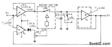
Combination of sillconix triple L144 opamp and DG181 analog switch eliminates errors of conventional diode circuits.Third opamp acts as comparator providing logic drive for operating SW1. Action of circuit is such that most positive analog input is stored. SW2, serves as reset switch.- Analog Switches and Their Applications, Siliconix, Santa Clara, CA, 1976, p 4-9. (View)
View full Circuit Diagram | Comments | Reading(0)
20_VDC_FET_VOLTMETER
Published:2009/7/15 2:07:00 Author:Jessie
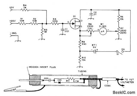
Has high input impedance as required for accurate measurements in solid-state circuit, Uses Motorola MPF102, HEP802, or equivalent N-channel JFET. If meter cannot be zeroed, change R7 to 10,000 ohms for greater zeroing range. 2-V range gives extra flexibility. Half-wave RF probe using 1N914 or equivalent high-speed switching diode responds to peak RF voltage being measured. R11 reduces peak value to RMS value. Connect probe to known 10-VRMS source, then adjust R11 so meter reads 10 V.-D, DeMaw and L. McCoy, Learning to Work with Semiconductors, QST, April 1974, p 20-25 and 41. (View)
View full Circuit Diagram | Comments | Reading(4272)
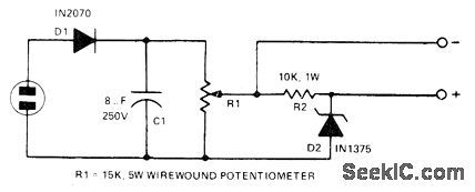
LINE_VOLTAGE_MONITOR_1
Published:2009/7/15 2:06:00 Author:Jessie
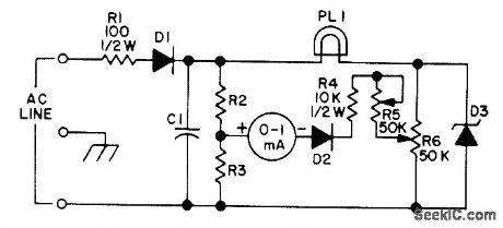
AC line voltage is rectified by D1 and filtered by C1. R2 and R3 form voltage divider that holds one meter terminal at half of rectified line voltage. DC is also applied to low-voltage calibration pot R6 through 3-W 117-V lamp or equivalent resistor PL1 which limits zener current. Any increase in line voltage increases voltage at R2-R3 junction while voltage at slider of R6 remains constant, so bridge unbalances and meter reads upscale. Zener is 70 to 100 V at 10W. R2 and R3 are equal and are from 8.2K to 15K. C1 is 50 to 100 /μF at 200 V, and diodes are power silicon with PIV above 200 and 100-mA rating.-W. P. Turner, Expanded Range Line Voltage Monitor, 73 Magazine, Jan. 1974, p 39. (View)
View full Circuit Diagram | Comments | Reading(904)
ABSOLUTE_VALUES
Published:2009/7/15 2:04:00 Author:Jessie
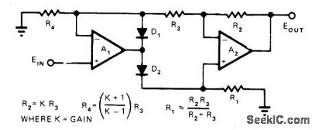
Positive output signal level is proportional to absolute value of input signal level, regardless of input polarity. Circuit combines simplicity with high input impedance, low output impedance, and greater than unity gain. Opamps A1 and A2 should have good CMRR and low offset and drift. D1 and D2 can be 1N914 For gain of 2.5, R1 and R3 are 1000 ohms, R2 is 2500, nd R4 is 2333 For unity gain, R4 is infinity and can be omitted R2 and R3 areequalue precision resistors Value of R1 is not critical at any gain.-R. Hofheimer, A Simple Absolute-Value Amplifier, EDN Magazine. June20, 1974, p 78 and 80. (View)
View full Circuit Diagram | Comments | Reading(1111)
10_RANGE_DC_VOLTMETER
Published:2009/7/15 3:25:00 Author:Jessie
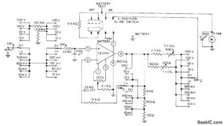
Rang switch is ganged between input and output circuits of CA3160 bipolar MOS opamp to permit selection of proper output voltage for feedback to terminal 2 of opamp through 10K current-limiting resistor. Circuit operates from single 8.4-V rnercury battery and draws about 500μA plus meter current;at input for full-scale reading, total supply current drain is about 1.5mA. –Circuit ldeas for PCA Liner ICs, RCA Solid State Division, Somerville, NJ, 1977, p 14. (View)
View full Circuit Diagram | Comments | Reading(1266)
WAVEFORM_PEAKS_AND_TROUGHS
Published:2009/7/15 2:56:00 Author:Jessie
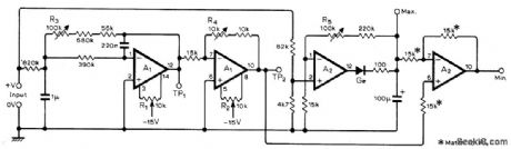
Used in data-logging systems to measure, limits of waveform superimposed on DC level. Requires two LM747CN (dual 741) ICs. Measurements are made with conventional DC voltmeter. Input signal is fed to precision peak detector A1. Same signal goes through active low-pass filter and inversion amplifier whose output at TP2 is the mean value. Differential amplifier A2 subtracts maximum from mean to give minimum value of input. For setup, short input and adjust R1 for 0 V at TP1, adjust R2 for 0 V at TP2, then apply +5 V to input and adjust R3 for+5 V at TP, adjust R4 for-5 V at TP2, and adjust R5 for +5V at Max. output terminal. –K. R. Brooks, Peak and Trough Detector, Wireless World, Feb. 1977, P 45. (View)
View full Circuit Diagram | Comments | Reading(2597)
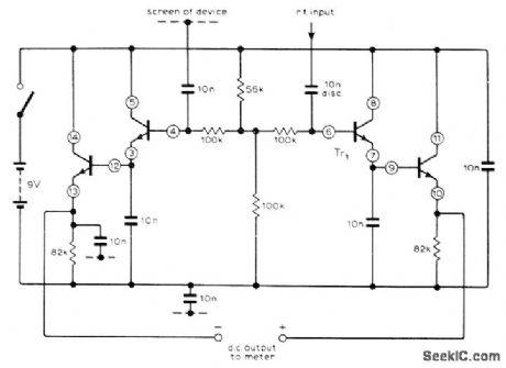
IR_REMOTE_CONTROL_TEST_SET
Published:2009/7/14 8:22:00 Author:May
This circuit can be used to check out operation ofthe IR remote control. (View)
View full Circuit Diagram | Comments | Reading(908)
| Pages:28/101 At 202122232425262728293031323334353637383940Under 20 |
Circuit Categories
power supply circuit
Amplifier Circuit
Basic Circuit
LED and Light Circuit
Sensor Circuit
Signal Processing
Electrical Equipment Circuit
Control Circuit
Remote Control Circuit
A/D-D/A Converter Circuit
Audio Circuit
Measuring and Test Circuit
Communication Circuit
Computer-Related Circuit
555 Circuit
Automotive Circuit
Repairing Circuit