
Measuring and Test Circuit
Index 25
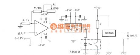
The DC voltage detected circuit with optical coupler
Published:2011/11/3 3:02:00 Author:Ecco | Keyword: DC voltage , detected circuit , optical coupler
View full Circuit Diagram | Comments | Reading(1160)
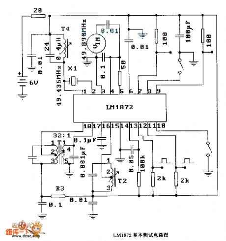
The basic test circuit diagram of LMl872
Published:2011/10/18 3:43:00 Author:Ecco | Keyword: basic test
View full Circuit Diagram | Comments | Reading(838)
Object motion detector circuit diagram
Published:2011/9/26 22:20:00 Author:Rebekka | Keyword: Object motion detector
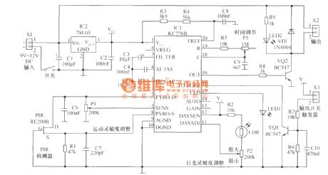
The heart of the motion detector movement detection circuit is motion detection chip IC1 (KC778B). The signal frequency from PIR sensor is low (0.1Hz ~ 10Hz) while the band is very wide, the chip will optimize it. The working voltage of KC778B is 4V ~ 15V, 78L05 requires 9V ~ 12V input voltage. The circuit has three sensitivity controllers. You can see a brief description in the figure. The detection sensitivity is cotrolled by the semi-variable resistor P1 connecting on chip 2 feet. When the level of the pin is connected to the sensor, thepotential is equal to the potential on pin 7(about 0.5V),and thesensitivity is the lowest. When pin 2 is grounded (about 0.125V), system sensitivity is the maximum. Sun sensitivity is controlled by semi-variable resistor and P2 photodiode LDR. Generally we hope that this detector does not work in the daytime, but only work at night, and itmay be connected to the lighting line. If you do not need this feature, you can connect Vcc pin on 12 feet and 11 feet will be vacant. P3 is adjusted by the timing pulse, the output pulse width in the range is more than 1.5s. (View)
View full Circuit Diagram | Comments | Reading(3570)
Pyroelectric infared detection circuit diagram
Published:2011/9/26 2:16:00 Author:Rebekka | Keyword: Pyroelectric infared detection
View full Circuit Diagram | Comments | Reading(1542)
M16 Experiment Board
Published:2011/8/2 1:18:00 Author:Ecco | Keyword: Experiment, Board
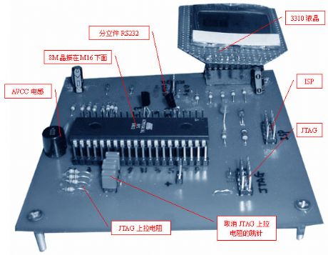
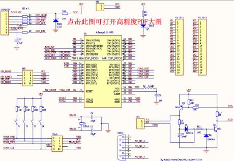
It includes the ISP, JTAG, 3310 LCD, and discrete parts RS232 serial port. When PC2-5 is not used as JTAG but IO port, it is designed to switch the situation to prevent the interference of JTAG, the design of Others, such as keyboards, LED, etc., they can be welded in the blank of experiment board.
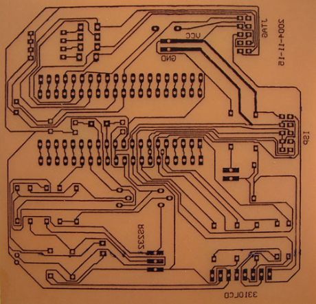
PCB diagram (it uses Protel dxp 2004 auto wiring. Thermal transfer legal board. The next picture shows the the circuit board after corrosion by ferric chloride and with thermal transfer layer and not beingsanding off ):
(View)
View full Circuit Diagram | Comments | Reading(1440)
DC capacitor tester circuit diagram composed of 555
Published:2011/9/18 22:37:00 Author:Ecco | Keyword: DC , capacitor , tester , 555, 10NF, 100NF, 100PF
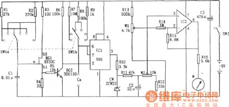
DC capacitor tester circuit diagram composed of 555 is shown as the chart. The tester is composed of the pulse generator, one-shot, DC amplifier and meter indication circuit. It can measures the npF ~ 10μF capacitor. The range is divided into 0 ~ 100PF, 0 ~ 1nF, 0 ~ 10nF, 0 ~ 100nF, 0 ~ 1μF, 0 ~ 10μF.
(View)
View full Circuit Diagram | Comments | Reading(5815)
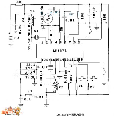
LMl872 basic test circuit diagram
Published:2011/9/1 2:23:00 Author:Ecco | Keyword: basic test
View full Circuit Diagram | Comments | Reading(865)
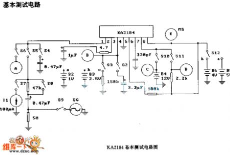
KA2184 basic test circuit diagram
Published:2011/9/1 2:21:00 Author:Ecco | Keyword: basic test
View full Circuit Diagram | Comments | Reading(1190)
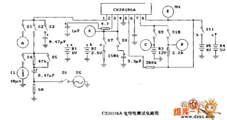
CX20106A electrical characteristics test circuit
Published:2011/9/14 2:46:00 Author:Ecco | Keyword: electrical characteristics test
View full Circuit Diagram | Comments | Reading(986)
CX20106A DC characteristics test circuit diagram
Published:2011/9/14 2:45:00 Author:Ecco | Keyword: DC characteristics test

View full Circuit Diagram | Comments | Reading(1111)
Detection model circuit
Published:2011/9/14 3:02:00 Author:Ecco | Keyword: Detection model

View full Circuit Diagram | Comments | Reading(938)
The Typical Circuit Diagram of Monolithick Color Scanner (LM9832)
Published:2011/9/8 6:19:00 Author:Ariel Wang | Keyword: Typical , Monolithick, scanner
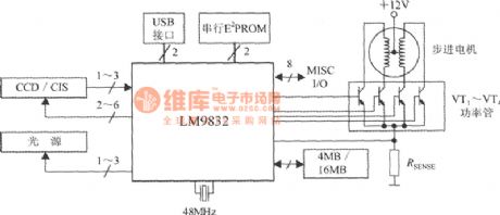
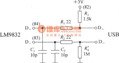
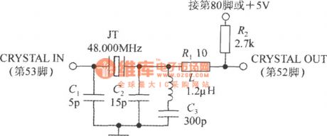
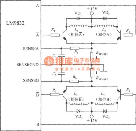
The circuit is constituted by the LM9832 typical single color scanner . RSENSE is the stepper motor current sense resistor. VT1 ~ VT4 are external drive tubes. LM9832 uses a USB interface.The data receives and sends through the D + and D-pins. These data is 3V differential signal. The circuit between LM9832 D + , D-pins-chip and the color scanner with a USB connector could be seen as the chart. R1 and R2 are two data lines limiting resistor. C1 and C2 are the capacitors to eliminate noise.R3 is the pull-up resistor , R4 is the pull-down resistor.
(View)
View full Circuit Diagram | Comments | Reading(1411)
Humidity measurement circuit with the thermistor
Published:2011/8/24 21:30:00 Author:Christina | Keyword: Humidity measurement, thermistor
The humidity measurement circuit with the thermistor is as shown in the figure. It uses the thermistor to measure the dry & wet ball temperature, and it directly displays the measured humidity through the current meter. The thermistor RT1, the resistor RP1 and R3 detect the temperature of the wet ball, and this temperature adds to the reverse phase input port of the A1; the thermistor RT2, the resistor R7 detect the temperature of the dry ball, and this temperature adds to the in-phase input port of A1. The C1 and R5 can be used to compensate the input frequency, the C2 can be used to compensate the output frequency, the RP2 can be used to adjust the sensitivity of the current meter.
(View)
View full Circuit Diagram | Comments | Reading(2523)
Temperature measurement circuit composed of the K-type thermocouple
Published:2011/9/8 19:59:00 Author:Christina | Keyword: Temperature measurement circuit, K-type, thermocouple
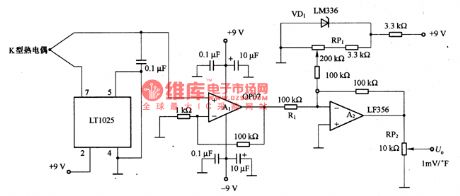
The temperature measurement circuit composed of the K-type thermocouple is as shown in the figure. In the temperature range of -40-500°F, the thermoelectric potential of the K-type thermocouple and the temperature has a good linear relationship, the relationship can be expressed as UY=0.226TX-0.707. In the formula, the UY is the thermoelectric potential (mV), the Tx is the temperature (°F). Tx=(UY十0.707)/0.226=(1OlUY十71.4)/22.8°F, so we get the 1mV/°F output. In the circuit, the LTl025 produces the cold contact point compensation voltage of the thermocouple, A1 amplifies the thermocouple output for 101 times, the stable voltage of WD1 is adjusted to 71.4mV by RP1, and it adds to the reverse phase input port of the addition amplifier.
(View)
View full Circuit Diagram | Comments | Reading(3210)
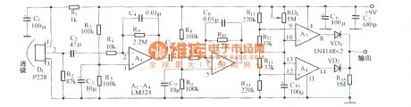
Circuit Diagram of Twin-Coil Metal Detector Composed of 555
Published:2011/9/7 0:47:00 Author:Vicky | Keyword: Twin-Coil Metal Detector
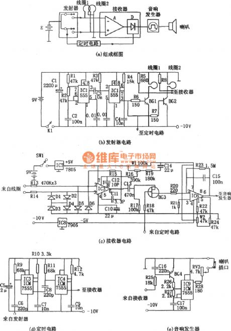
Picture (a) is a twin-coil metal detector. It iscomposed ofprobing head, emitter, receptor, timer, and audio transmitter etc.
As shown in picture (B), emitter in made of multivibrator (IC1,R1,R2,C2) and monostable timer (IC2,R4,C4). The timer IC2 is triggered by the pulse sent by multivibraror IC1. The vibrator’s frequency is f=1.44/(R1+2R2)C2.
Picture (C) is receiving circuit which is mainly made of difference amplifier and detection amplifier.
Picture (d) is timer circuit. It iscomposed oftwo monostable time-delay circuit which are composed of IC3,R10,C7 and IC4,R12,C9 respectively. The IC4 is controlled by the output of IC3. The delay time of IC3 is td=l.1R12C9 while IC4 is td2=1.1R10C7.
Picture (e) is audio generator. The multivibrator which is composed of 555(IC9), BG4, R26, R27,C17 is its core part. When there is no metal-actuated signal, BG4 is stopped by the signal sent out by pin ⑥ of IC6, the multivibrator and the correspondent speak do not work.
(View)
View full Circuit Diagram | Comments | Reading(3939)
Single-chip RF Power Measurement System MAX2015-made RF Signal Reception Srength Idicator Crcuit
Published:2011/5/16 4:37:00 Author:Sharon | Keyword: Single-chip, RF Power Measurement, Signal Reception Srength Idicator
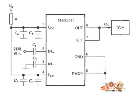
RF signal receiving strength indicator circuit formed by MAX2015 is as shown in the figure. RF signals pass through the coupling capacitor C1 to IN +end and IN-end,then to ground by the coupling capacitor C2. IN +, IN-end internal 50Ω resistor can be matched with the 50MHz ~ 3.0GHz RF circuits. The capacity of C1 and C2 are both 680pF. C3 and C4 are power supply decoupling capacitors. Link OUT and SET-side to each other by short circuit, and MAX2015 will enter the test mode. The output voltage Uo of OUT terminal is sent to the digital voltage meter, showing the received RF signal strength.
When power supply is Ucc=+2.7~3.6V, R=0Ω; when Ucc=+4.75~5.25V, R=75Ω( Difference ranging between -1% and +1% is allowable).PWDN is should be linked to ground. (View)
View full Circuit Diagram | Comments | Reading(1331)
Triangle multidrop parallel connection three-phase motor winding short circuit detection circuit
Published:2011/9/8 20:01:00 Author:Christina | Keyword: Triangle, multidrop, parallel connection, three-phase, motor, winding, short circuit, detection circuit
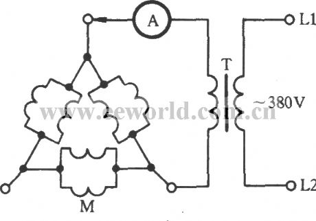
For the triangle multidrop parallel connection three-phase motor, you need to separates the adapter connector of the winding. As the figure shows, you can connect the winding into the triangle, and connect one port with the secondary stage of the welding transformer T, another port of T is connected with an ammeter. After the power is connected, you need to connect the hand (which is connected with the ammeter) with the other two ends of the winding respectively to compare the current, the phase which has the smaller current value is the short circuit winding.
(View)
View full Circuit Diagram | Comments | Reading(3294)
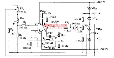
Mental state tester circuit diagram
Published:2011/9/8 3:50:00 Author:Lucas | Keyword: Mental state tester
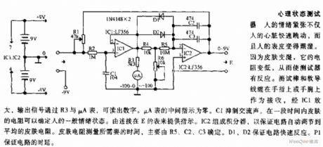
People's emotional stress not only makes the human heart beat fast, and people's skin become wet. Because the skin becomes wet, its resistance becomes low, so that the test device reacts. Test bars and soft wires are wrapped around the fingers or wrist as a receiver, the output signal is amplified by IC1 and read out by μA meter and R3. μA middle indicates 0, then C1 suppresses hum. During the period of time, the skin resistance can determine people's general emotional state, which is indicated by the table connected to the E. IC2 forms the integrator to ensure that the circuit automatically adjusts the average skin resistance.
(View)
View full Circuit Diagram | Comments | Reading(1238)
Starlike multidrop parallel connection three-phase electromotor winding open circuit checking circuit
Published:2011/9/8 20:31:00 Author:Christina | Keyword: Starlike, multidrop, parallel connection, three-phase, electromotor, winding, open circuit, checking circuit
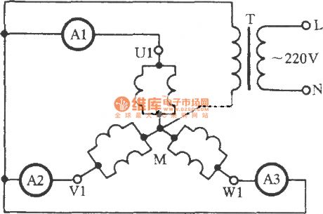
The stator windings of the three-phase electromotor which is more than 10KW always use the varnished wire parallel winding and the Multidrop parallel connection. In one phase winding, if one or more wires cut off, you are difficult to judge by using the light, you can use the three-phase current balance method. The circuit is as shown in the figure, it uses the single-phase AC arc welding machine transformer T as the power supply, the three ammeters A1, A2 and A3 are connected with the U1, V1 and W1 respectively. After the power is connected, you can observe the current values of the three ammeters. In normal condition, the values are different.
(View)
View full Circuit Diagram | Comments | Reading(1537)
Single-chip RF Power Measurement System MAX2015-made RF Power Control System Circuit
Published:2011/5/16 20:40:00 Author:Sharon | Keyword: Single-chip, RF Power Measurement, Power Control System
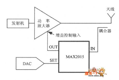
What shows in the figure is the RF power control system circuit formed by single-chip RF power measurement system MAX2015. The set point voltage USET provided by D / A converter (DAC) is linked to the SET side of MAX2015. RF signals emitted by the antenna pass through the coupler to the input of MAX2015. MAX2015's output voltage Uo acts as input signal of the variable gain amplifier and is used to control the transmission power. (View)
View full Circuit Diagram | Comments | Reading(1131)
| Pages:25/101 At 202122232425262728293031323334353637383940Under 20 |
Circuit Categories
power supply circuit
Amplifier Circuit
Basic Circuit
LED and Light Circuit
Sensor Circuit
Signal Processing
Electrical Equipment Circuit
Control Circuit
Remote Control Circuit
A/D-D/A Converter Circuit
Audio Circuit
Measuring and Test Circuit
Communication Circuit
Computer-Related Circuit
555 Circuit
Automotive Circuit
Repairing Circuit