
Measuring and Test Circuit
Index 31
MULTI_SCALE_COUNTER
Published:2009/7/14 1:50:00 Author:May
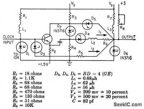
Changing value of L2 changes scale factor in range of 2 to 8. Circuit operates to 10 Mc at scale of 5.-C.A.Budde. One-Stage Scale Needs No Complex Feedback, Electroics.36:39,p32-33 (View)
View full Circuit Diagram | Comments | Reading(986)
POLARITY_COINCIDENCE_MULTIPLIER
Published:2009/7/15 3:43:00 Author:Jessie
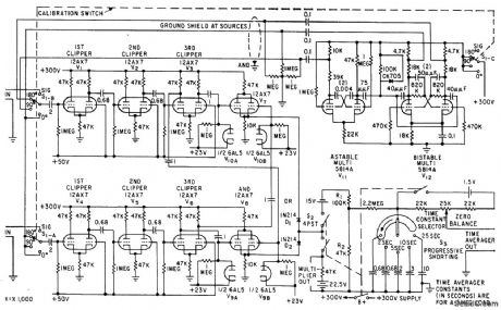
Detects weak low-frequency signals in high-noise background, with output indicating presence and phase shift of signals received at dual inputs. Accuracy is within 1% for inputs of 1 to 500 cps.-B. M. Rosenheck, Detecting Signals by Polarity Coincidence, Electronics, 33:5, p 67-69. (View)
View full Circuit Diagram | Comments | Reading(1069)
AUDIBLE_VM
Published:2009/7/15 3:40:00 Author:Jessie
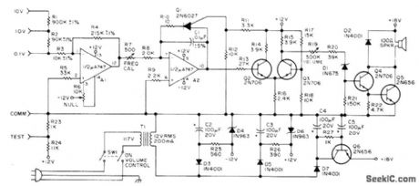
Voltage controlled audio oscillator A2 serves for rough measurements of up to 10 VDC, allowing user to keep eyes on test probe during troubleshooting. Voltmeter circuit has input impedance of 100,000 ohms per volt. Separate input jacks provide full-scale ranges of 0.1, 1, and 10 V, with full-scale voltage for each producing 1000-Hz tone. Voltage less that fullscale produces proportionately lower frequency. Article describes circuit operation in detail.-S. Johnson, An Audible Voltmeter, 73 Magazine, Aug, 1974, p 55 and 57-59.
(View)
View full Circuit Diagram | Comments | Reading(1318)
POWER_SUPPLY_MONITOR
Published:2009/7/14 3:35:00 Author:May
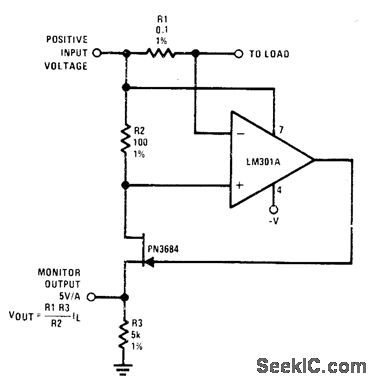
Ra senses output current of power supply. PN3684 JFET is used as buffer because source and drain currents arb equal, so monitor output voltage accurately refleets current flow of power supply.- FET Databook, National Semiconductor, Santa Clara, CA, 1977, p 6-26-6-36. (View)
View full Circuit Diagram | Comments | Reading(0)
AUTOMATIC_POLARITY_SWITCHING
Published:2009/7/15 20:37:00 Author:Jessie
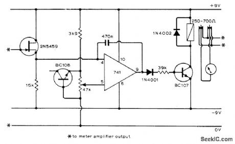
Can be added to almost any high-impedance voltmeter to give automatic reversal of polarity as required during measurements. Additional contacts on relay can be used to switch polarity indicators. FET input prevents meter shunting. Feedback is used in opamp comparator to speed switching action.-H. Wedemeyer, Auto Polarity Switching for Voltmeters, Wireless World, Oct. 1974, p 380.
(View)
View full Circuit Diagram | Comments | Reading(1740)
FET_AC_VOLTMETER
Published:2009/7/15 20:36:00 Author:Jessie
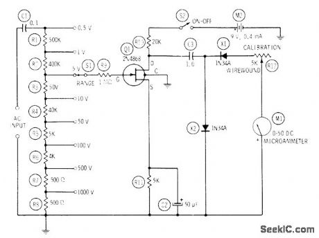
Covers 0-1000 VRMS in eight ranges. Frequency response referred to 1 kHz is down 3.5 dB at 50 Hz and down 2 dB at 50 kHz. Meter deflection is proportional to average value of AC signal voltage, but meter can be calibrated to read RMS voltages on sine-wave basis. Use 1% resistors for voltage divider. Useful for audio and ultrasonic measurements and tests.-R. P. Turner, FET Circuits, Howard W. Sams, Indianapolis, IN, 1977, 2nd Ed., p 122-124. (View)
View full Circuit Diagram | Comments | Reading(1328)
3SUP3_SUP_SUB4_SUB_DIGIT_METER
Published:2009/7/15 20:35:00 Author:Jessie
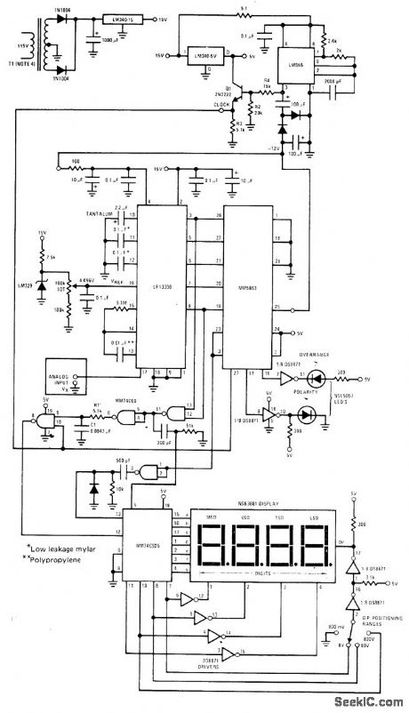
National MM5863 12-bit binary building binary block is used with LF13300 analog section of A/D converter to provide ±8191 counts on NSB3881 display MM74C926 CMOS counter is connected to count clock pulses during ramp reference cycle of LF13300. Counts are latched into display when comparator output trips and goes low Operates from single 15-V supply with aid of DC/DC converter LM555 serves as clock and generates required negative supply voltages All diodes are 1N914. -″MOS/LSI Data Databook,″National Semiconductor, Santa Clara, CA, 1977, p 5-2-5-22. (View)
View full Circuit Diagram | Comments | Reading(2392)
FET_VOLTMETER_2
Published:2009/7/15 20:30:00 Author:Jessie
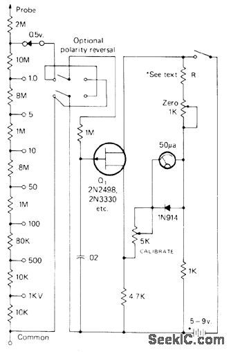
Voltage divider provides 22-megohm resistance for FET version of VTVM. JFET Q, is used as source follower, Meter is connected in bridge that is balanced with 1K zero-adjust pot. With proper selection of R, pot can also be used to set zero point of circuit to half scale. Accuracy depends primarily on divider chain. Total current drain rarely exceeds 1 mA, giving long life for almost any type of battery.- I. Math, Math's Notes, CQ, Oct. 1974, p 26-27. (View)
View full Circuit Diagram | Comments | Reading(1677)
AC_LINE_POLARITY_METER
Published:2009/7/15 20:29:00 Author:Jessie
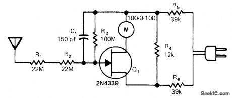
Used to determine correctness of ground wiring in receptacle. Circuit compares voltage waveform on line conductors with AC potential of 10-40 V at 60 Hz picked up by antenna which can be human body. Circuit is synchronous demodulator that conducts on alternate half-cycles depending on whether gate voltage of JFET is positive with respect to source or drain. Zero-center DC milliammeter serves as readout. If plug is inserted into receptacle having balanced power line, milliammetet stays at center to indicate lack of ground. With properly grounded receptacle, meter swings full scale in either direction.-T. Gross, Indicator Shows Correct Wiring Polarity, EDN Magazine, Oct. 20, 1978, p 150 and 152. (View)
View full Circuit Diagram | Comments | Reading(1597)
04_200_MHz_VM
Published:2009/7/15 20:27:00 Author:Jessie
Battery-operated RF voltmeter has full-scale ranges from 0.03 V to 10 V and flat frequency response from 40 kHz to over 200 MHz. Circuit uses voltage-doubling rectifier-type probe CR1-CR2 followed by high-gain DC amplifier driving milliammeter. Article covers construction and calibration in detail.-J. M. Lomasney, Sensitive RF Voltmeter, 73 Magazine, Dec. 1973, p 53-62. (View)
View full Circuit Diagram | Comments | Reading(4979)
PHONE_CALL_COUNTER
Published:2009/7/14 3:30:00 Author:May
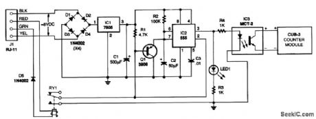
This circuit counts any string of rings as one call, regardless of duration. If someone hangs up after 1 ring or 10, the counter advances by 1. Similarly, if someone reaches an answering machine and hangs up, or leaves a message, the counter still advances by one call. The counter circuit must ignore signals and react only to the 90-Vac that comes in when the phone is ringing. Because the counter circuit is isolated from the phone line, it needs its own power supply. With some phone systems, power can be pro-vided by the yellow and black wires of the phone line, which typically are connected to a small transformer that provides about 8 Vac. The bridge rectifier Dl to D4, voltage regulator IC1, and filter capacitor C1 convert that to 5 Vdc to power the circuit. If your phone line does not have active yellow and black wires, 6.3 Vac must be connected to the input of the rectifier. Timer IC2 is triggered by relay RY1, which has a coil voltage of about 48 V. Because diode D5 is reverse-biased relative to the normal dc across the phone line, it will pass only partially rectified ac. When the phone rings, D5 passes a partially rectified 90 V, which is enough to energize the relay. Actually, the relay will chatter at about 20 Hz during a ring signal because the rectified voltage is not pure dc. This generates a rapid string of pulses to trigger the timer. But because the timer operates in a retriggerable mode, its output re-mains high for the duration of the rings. The NE555 timer (IC2) is wired in a retriggerable, monostable configuration. The output stays high for a length of time determined by the time constant, 1.1× R2× C2 Because the timer is retriggered with each ring signal, its output will remain high for about 5.5 seconds after the phone stops ringing. The counter will advance by one count whenever the output goes high. Indicator LED1 shows when the phone is ringing and when the output of the timer is high. The high output activates optoisolator IC3 and advances the counter by 1. The counter can be any digital or electromechanical counter whose operation is not affected by the duration of the trigger signal. (View)
View full Circuit Diagram | Comments | Reading(2676)
4SUP1_SUP_SUB2_SUB_DIGIT_METER
Published:2009/7/15 20:23:00 Author:Jessie
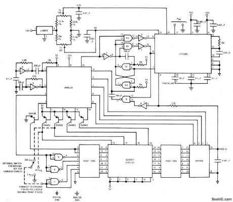
National MM5330 BCD building block is used with LF13300 analog section of A/D converter to provide ±19,999 counts on NSB5917 display. Circuit contains counters, latches, and multiplexing system for four full digits of display with one decoder/driver, along with sign bit that is valid during overrange and 10,000-count numeral 1, LF13300 has automatic zeroing of all offset voltages. Operation is based on code conversion of number of counts made by MM5330 before comparator crossing is detected. Switch gives choice of 2-, 20-, and 200 V full-scale ranges. Inverters are MM74C14 hex Schmitt triggers. Two-letter NAND gates are MM74C00 CMOS quad NAND gates. One-letter NAND gates (A, B, etc) are DM7400 TTL quad NAND gates.- MOS/LSI Databook, Nation-al Semiconductor, Santa Clara, CA, 1977, p 5-2-5-22.
(View)
View full Circuit Diagram | Comments | Reading(1155)
NULL_VOLTMETER
Published:2009/7/15 20:20:00 Author:Jessie
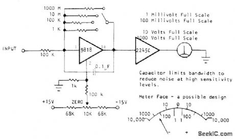
Logarithmic voltmeter using Optical Electronics 9818 opamp and 2245C four-decade bipolar logarithmic function can serve as output indicator of Wheatstone bridge, as solid-state galvanometer, or as indicator for differentia[ voltmeter or comparison bridge. Meter scale values are relative; basic sensitivity of circuit corresponds to 1 on scale, representing 100 nV. With this sensitivity, 1 mV gives full-scale reading. Other three positions of range switch give 100 mV, 10 V, and 1000 V for full scale, when using 10-0-10 V meter. Inherent limiting of opamp protects circuit from overvoltage damage.- A Logarithmic Null-Volt-meter Design, Optical Electronics, Tucson, AZ, Application Tip 10084. (View)
View full Circuit Diagram | Comments | Reading(2246)
FET_VOLTMETER_1
Published:2009/7/15 20:17:00 Author:Jessie
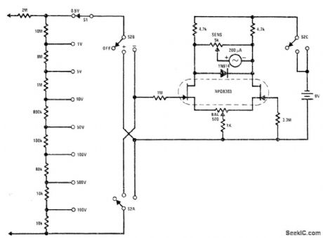
Performance is comparable to that of vacuum-tube voltmeter, without requirement of AC supply Drift rate is far superior to that of tubes, allowing 0.5-V full-scale range. Uses low-leakage low-noise NPD8303 dual JFET. - FET Databook, National Semiconductor, Santa Clara, CA, 1977, p 6-26-6-36.
(View)
View full Circuit Diagram | Comments | Reading(0)
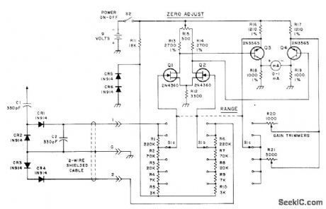
HIGH_INPUT_IMPEDANCE
Published:2009/7/15 20:16:00 Author:Jessie
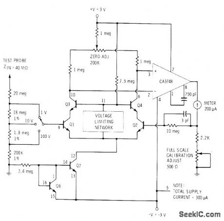
All transistors are on RCA CA3095 transistor array. Q1-Q4 are connected to form bridge, with voltage to be measured applied to base 9. Circuit balance and calibration are achieved by varying DC voltage applied to base of a2. Q7 and O8 serve as constant-current source for cascode differential amplifier connection of Q1-Q4. Differential out-put of bridge is applied to differential input of CA3748 opamp driving meter. Switch gives choice of three voltage ranges,-E. M. Noll, Linear IC Principles, Experiments, and Projects, Howard W. Sams, Indianapolis, IN, 1974, p327.
(View)
View full Circuit Diagram | Comments | Reading(0)
ELEVEN_BIT_DECODER
Published:2009/7/14 2:50:00 Author:May
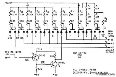
Well-regulated transistor power supply and binary-weighted network of precision wire-wound resistors give high-precision conversion of 11-bit digital value to current analog. Output goes to magnetic modulator. Regulated 320-v supply(not shown) uses silicon junction diodes in full-wave bridge, with silicon zener diode as reference.-N. Aron,Precise Converter Takes Current Analog of Digital Voltage Pulses, Electronics,35:32, p 68-71. (View)
View full Circuit Diagram | Comments | Reading(1203)
BATTERY_TESTER
Published:2009/7/14 2:22:00 Author:May
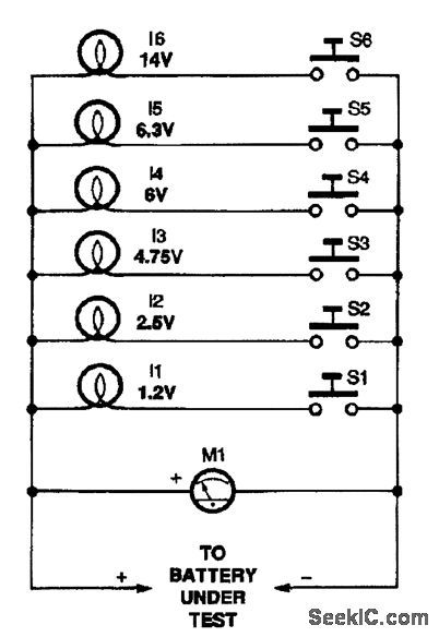
Although deceptively simple, this battery tester can help you weed out marginal cells that might otherwise test good. Six incandescent lamps, chosen for their voltage and current ratings, are selected as a load for the battery under test. The meter (M1) and the lamp's brightness will give a good indication of a battery's output capacity. In addition, because the inrush current that occurs when the lamp is first connected across the battery is much higher than the rated operation value, the circuit makes it easy to spot marginal cells. To use the circuit, connect a battery and observe the measured voltage on M1. Then close the switch that corresponds to the meter's reading and/or the battery's rated voltage and observe the brightness of the appropriate lamp. Be careful to select the right lamp for testing. Never test using a lamp whose voltage rating is more than 30 percent lower than the battery's rating. Otherwise, damage to the lamp could result if the battery under test is good.
(View)
View full Circuit Diagram | Comments | Reading(0)
LADDER_TYPE_NETWORK_DECODER
Published:2009/7/14 2:45:00 Author:May
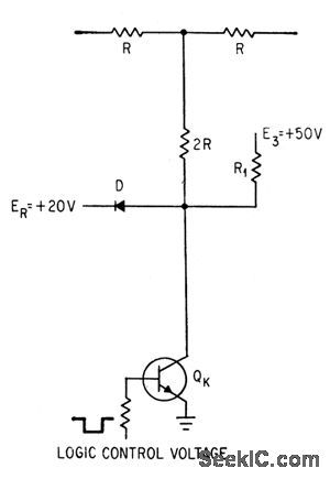
Transistor replaces spdt switch for binary conversion of analog signal. Transistor's own saturation voltage (shown as ground for simplicity) serves as lower reference, while diode provides upper reference. Chief drawback is poor temperature stability.-C. R. Pearman and A.E. Popodi, How to Design High-Speed D-A Converters, Electronics, 37:8, p 28-32. (View)
View full Circuit Diagram | Comments | Reading(867)
TIMER_COUNTER
Published:2009/7/14 2:34:00 Author:May
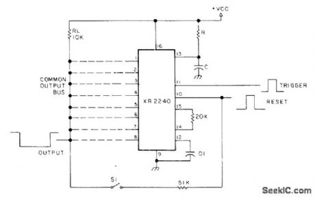
Basic circuit using XR2240 programmable timer/counter acts as programmable mono when S1 is closed, with output pulse width being a multiple in binary of RC seconds. With 8-bit binary counter, time delays range from 1 RC to 255 RC seconds. As an exi ample, if only pin 6 (dividing input frequency by 32) is connected to common output bus, duration of output pulse will be 32 RC seconds. Similarly, with pins 1, 2, 5, and 7 connected to bus, delay is 83 RC seconds. With S1 open for astable operation, output frequency is 1/t hertz where t is multiple of RC from 1 to 255. VCC is 4-15 V. - H. M. Berlin, IC Timer Review, 73 Magazine, Jan. 1978, p 40-45. (View)
View full Circuit Diagram | Comments | Reading(3258)
5_W_ON_80_OR_40_m
Published:2009/7/14 2:17:00 Author:May
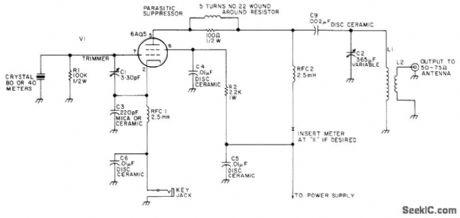
Single 6AQ5 operating from 200-V supply can cover all states and some DX with CE on 40 meters as low-power amateur radio station Antenna can be simple dipole 8 feet high L1 is 15 turns No 22 enamel on 11/4-inch plastic form, with 3 turns of insulated wire wound around cold end of L1 for L2 Article covers construction and operation and gives suitable 200-V voltage-doubling power supply circuit.-S.Dunn, ORP Fun on 40 and 80, 73 Magazine.Oct 1976, p 44-46. (View)
View full Circuit Diagram | Comments | Reading(967)
| Pages:31/101 At 202122232425262728293031323334353637383940Under 20 |
Circuit Categories
power supply circuit
Amplifier Circuit
Basic Circuit
LED and Light Circuit
Sensor Circuit
Signal Processing
Electrical Equipment Circuit
Control Circuit
Remote Control Circuit
A/D-D/A Converter Circuit
Audio Circuit
Measuring and Test Circuit
Communication Circuit
Computer-Related Circuit
555 Circuit
Automotive Circuit
Repairing Circuit