
Measuring and Test Circuit
Index 53
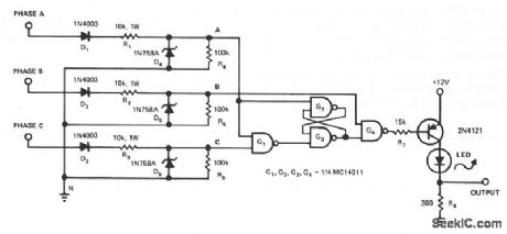
PHASE_SEQUENCE_DETECTOR
Published:2009/7/9 2:13:00 Author:May
View full Circuit Diagram | Comments | Reading(0)
SLIDE_TIMER
Published:2009/7/9 1:51:00 Author:May


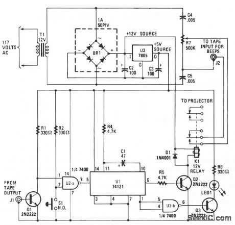
This circuit will record commentary and/or music on one track of a tape and put the beeps that change the slides on another track. Gate U2a is used to trigger U1, which is configured as a timer when a pulse is received from either the tape input or via pushbutton switch S1. Timer U2 outputs one pulse for every input pulse received, no matter how long S1 is depressed.The Q output of U2 at pin 1 is fed to U2b, which is set up as an inverter. When pin 1 of U1 becomes low, Q3 is activated, lighting LED1. The Q output of UI at pin 6 is tied to the base of Q2, through R5, so that when pin 6 becomes high, Q2 is turned on. When Q2 is turned on, relay K1 is energized, and a signal is fed to the tape input through J2. The second set of contacts of K1 are used to trigger the projector.Power for the circuit is provided by a 7805 regulator. The unregulated 12 V output of BR1 is used to power the relay. The 12-V relay needs to have two sets of contacts as shown: to advance the projector, and to supply the beeps when recording. The LED indicates projector advance.To record the beeps, connect beeper jack J2 to the input of the tape recorder and connect the controller to the projector-advance plug. The 60-Hz line frequency is used to produce beeps that are recorded on half of the stereo tape. The other track is used for commentary. The beeper output is controlled via 500-KΩ potentiometer R6.
Use pushbutton switch S1 to put the beeps on the tape, where required, to advance the projector.The beep length is automatic, and the projector will advance once for every push of S1.When presenting your program, disconnect one speaker from the recorder, and connect the recorder to the jack on the controller and plug into the earphone jack. Connect the controller to the projector. The beeps will not be heard and the projector will advance at precisely the correct time. (View)
View full Circuit Diagram | Comments | Reading(953)
CIRCUIT_TRACER
Published:2009/7/20 20:45:00 Author:Jessie
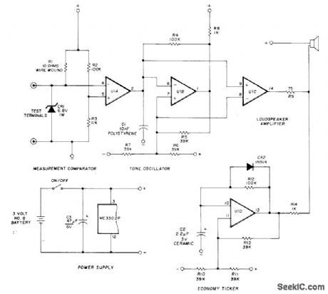
Continuity tester delivers continuous audio tone when its test terminals are connected by resistance less than about 1 ohm. Circuit under test does not receive more than 3 V or 300 mA, depending on resistance between terminals. Tester ticks softly when switched on but is open-circuited, as reminder that battery drain is then about 0.8 mA. Tester uses sections of Motorola low-power MC3302P quad comparator as measurement comparator, 600-Hz tone oscillator, AF amplifier, and ticker. Pins 3 and 12 of IC are used in power supply.-R. C. Marshall, Continuity Bleeper for Circuit Tracing, Ham Radio, July 1977, p 67-69. (View)
View full Circuit Diagram | Comments | Reading(1151)
LINEAR_SCALE_OHMMETER_1
Published:2009/7/20 20:44:00 Author:Jessie
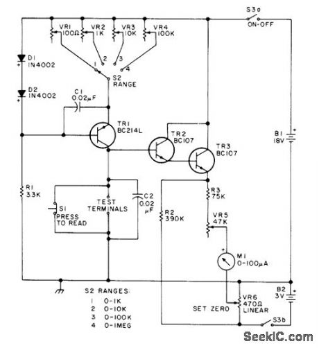
Provides accurate measurements of resistance in four ranges,with linear scale at high end of each.-Circuits,73 Magazine.Feb 1977,p27. (View)
View full Circuit Diagram | Comments | Reading(2022)
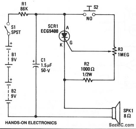
SCR_RELAXATION_OSCILLATOR
Published:2009/7/9 1:45:00 Author:May
View full Circuit Diagram | Comments | Reading(1361)
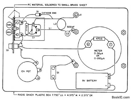
FLASH_METER
Published:2009/7/9 1:44:00 Author:May
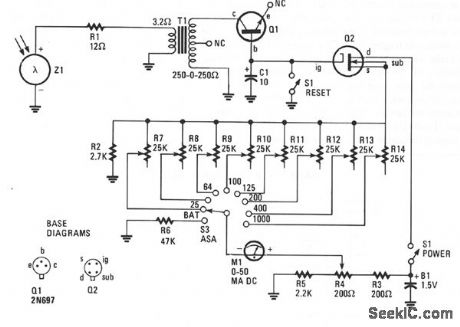
Insulated-gate, field-effect transistor (IGFET), Q2 and silicon photo cell Z1 form the heart of this circuit. Transformer T1 is an audio-output type, but it's reversed in the circuit. A sudden flash from a photoflash unit detected by Z1 sends a voltage pulse through the low-impedance winding of T1 via R1. That voltage pulse is stepped-up in T1's 500-Ω, primary winding before being rectified by Q1. Transistor Q1 is used as a diode; its emitter lead was snipped off close to the case. Q1 then charges C1 to a value proportional to the amplitude of the electrical pulse generated by the light from a flash unit.
Capacitor C1 controls the current flowing through Q2, which has a very high-input impedance. The current through Q2 is read by meter Ml, a 0-50 μA dc unit, which has been calibrated in f-stops. The extremely high internal resistances of Q1 and Q2 will allow C1 to retain its charge for several minutes; this is more than enough time for you to take your reading of M1. The charge on C1 is shorted to ground and returned to 0 V by depressing reset button S1. The flashmate is ready to read the next photoflash. Trim potentiometers, R7 through R14, are adjusted to values which will yield correct readings for corresponding film sensitivities, or exposure indexes. (View)
View full Circuit Diagram | Comments | Reading(923)
DOWN_TO_005_OHM
Published:2009/7/20 20:40:00 Author:Jessie
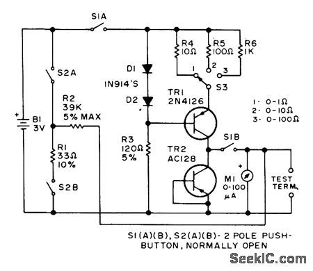
Switch S3 gives choice of three ranges in linear ohmmeter circuit developed for measuring very small values of resistance. Values of R4, R5, and R6 require adjustment during initial calibration.-Circuits, 73 Magazine, June 1975, p 161. (View)
View full Circuit Diagram | Comments | Reading(2378)
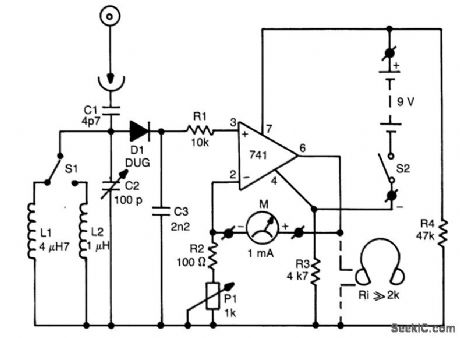
FIELD_STRENGTH_METER
Published:2009/7/8 23:06:00 Author:May
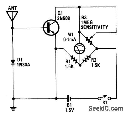
This field-strength meter is basically a bridge circuit that is equipped with a 0-to-1-mA meter as a readout. (View)
View full Circuit Diagram | Comments | Reading(0)
TIMED_SLOPE_SAMPLING
Published:2009/7/20 21:31:00 Author:Jessie
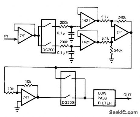
Circuit measures rate of signal change for slowly varying signals (changing less than 1 V/min) by using sample-and-hold circuit to store instantaneous sample.After compatible time interval, sample is com-pared with new input current value; difference is then the desired slope. One limitation is that offset errors added to stored signal near zero voltage can cause large errors in the derivative. Circuit is highly sensitive to noise spikes during sampling.-R. E. Bober, This Derivative Circuit Handles Slowly Varying Signals, EDN Magazine, Jan. 20, 1976, p 82. (View)
View full Circuit Diagram | Comments | Reading(791)
NONINVERTING_SAMPLE_AND_HOLD_1
Published:2009/7/20 21:29:00 Author:Jessie
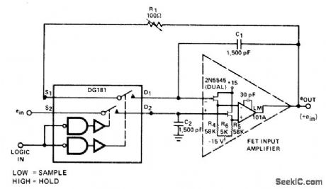
DG181 JFET analog switch provides best combination of settling speed and inherent charge transfer accuracy for 2N5545 FET-input opamp for high-speed sample-and-hold applications.- Analog Switches and Their Applications, Siliconix, Santa Clara, CA, 1976, p 7-60. (View)
View full Circuit Diagram | Comments | Reading(694)
CABLE_TESTER
Published:2009/7/20 21:04:00 Author:Jessie
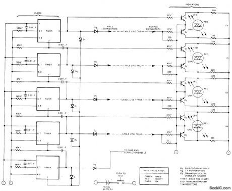
Five Signetics NE555V timers check all lines of four-conductor cable for opens and for short-circuit conditions, Differential transistor pall at one end of each cable line remains balanced as long as clock pulses at opposite ends of line are identical. Clock pulse at timer end of one line turns on green LED to indicate open in line. Clock pulse only at transistor end of line turns on red LED to indicate that line is shorted With good cable line, neither LED is on.- Signetics Analog Data Manual, signetics,Sunnyvale,CA,1977,p730. (View)
View full Circuit Diagram | Comments | Reading(0)
POT_TESTER
Published:2009/7/20 20:55:00 Author:Jessie
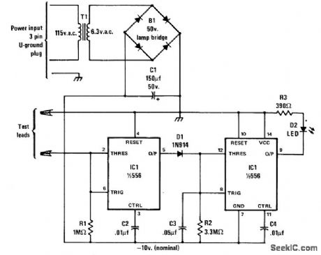
Developed for testing noisy 10K wirewound linear pots used in control of theatrical lighting system. Circuit detects any mo-mentary open and drives LED to produce visible flash lasting about 0.1 s. Circuit operates from -10 V provided by bridge and AC transformer.Left half of IC1 acts as comparator whose out-put stays low as long as input is above thresh-old voltage. When pot passes open point, pin 5 goes high and charges C3, making right half of IC1 turn on LED.-C. J. Shakespeare, Test Your Pot, Modem Electronics, Oct. 1978, p 38-39. (View)
View full Circuit Diagram | Comments | Reading(811)
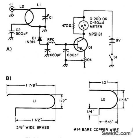
SIGNAL_STRENGTH_METER
Published:2009/7/8 23:09:00 Author:May
This fteld-strength meter is useful for antenna testing. It covers 6 to 60 MHz and uses a rugged 0-to-1 mA meter. A 9-V battery supplies power. The unit can be mounted in a small plastic or metal case. (View)
View full Circuit Diagram | Comments | Reading(1069)
Digitally_programmed_set_point_comparator
Published:2009/7/21 3:04:00 Author:Jessie
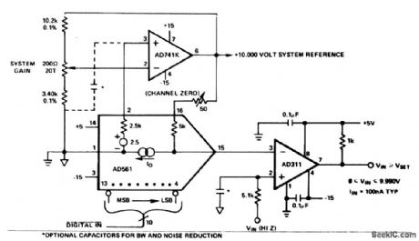
Digitally programmed set point comparator (courtesy Analog Devices, Inc.). (View)
View full Circuit Diagram | Comments | Reading(687)
UHF_FIELD_STRENGTH_METER
Published:2009/7/8 22:34:00 Author:May
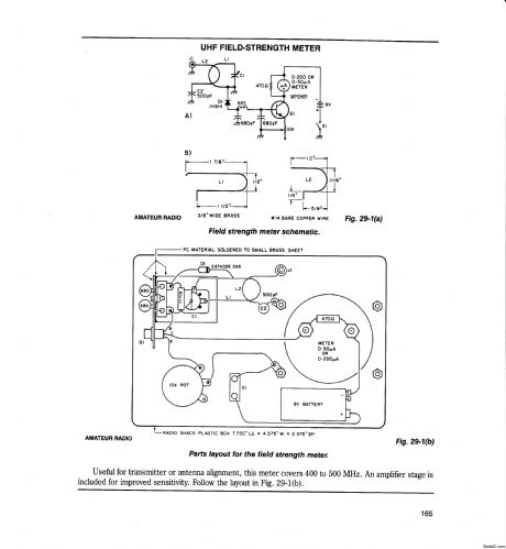
This field-strength meter is basically a bridge circuit that is equipped with a 0-to-1-mA meter as a readout. (View)
View full Circuit Diagram | Comments | Reading(3045)
Color_TV_chroma_demodulator
Published:2009/7/21 4:43:00 Author:Jessie

Color TV chroma demodulator. The ECG1048 is a 14-pin DlPwith an end metal tab. The ECG1089 partially shown is a color processor chip (courtesy GTE Sylvania Incorporated). (View)
View full Circuit Diagram | Comments | Reading(836)
Typical_ECG746_Video_IF_Amplifier_and_ECG747_Low_Level_Video_Detector_Circuit
Published:2009/7/21 4:40:00 Author:Jessie
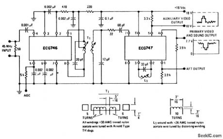
Typical ECG746 Video IF Amplifier and ECG747 Low-Level Video Detector Circuit. (View)
View full Circuit Diagram | Comments | Reading(772)
AM_IF_and_detector
Published:2009/7/23 21:44:00 Author:Jessie
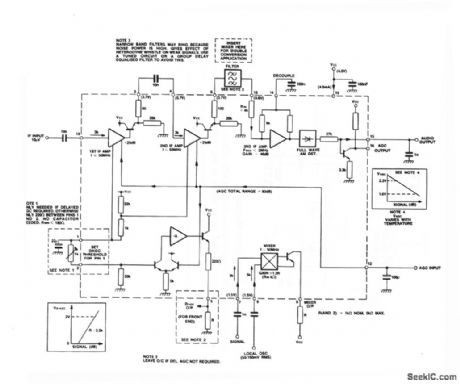
The SL6701 shown is a single- or double-conversion IF amplifier anddetector for AM-radio applications. Normally,the SL6701 is fed with a first IFsignal of 10.7 or 21.4 MHz There is amixerforconversion to the firstorsecond IF,a detector, and an AGC generator with optional delayed output. (View)
View full Circuit Diagram | Comments | Reading(978)
On_leakage_current_tests
Published:2009/7/23 21:52:00 Author:Jessie
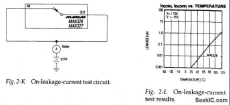
Figure 2-K shows a basic test circuit for measuring on-leakage-current I D(ON) for the MAX326/27. Figure 2-L shows how I D(ON) changes with temperature. (View)
View full Circuit Diagram | Comments | Reading(982)
CONTACT_TESTER
Published:2009/7/23 21:53:00 Author:Jessie
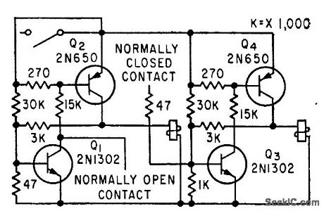
Determines whether contacts have maintained their normally open or closed conditions during shock and vibration testing. Dual circuit monitors both types of contact.-F. W. Kear, Contact Monitoring for Vibration Tests, Electronics, 33:15, p 78-79. (View)
View full Circuit Diagram | Comments | Reading(764)
| Pages:53/101 At 204142434445464748495051525354555657585960Under 20 |
Circuit Categories
power supply circuit
Amplifier Circuit
Basic Circuit
LED and Light Circuit
Sensor Circuit
Signal Processing
Electrical Equipment Circuit
Control Circuit
Remote Control Circuit
A/D-D/A Converter Circuit
Audio Circuit
Measuring and Test Circuit
Communication Circuit
Computer-Related Circuit
555 Circuit
Automotive Circuit
Repairing Circuit