
Measuring and Test Circuit
Index 44
RF_TRANSISTOR_TESTER
Published:2009/7/11 1:45:00 Author:May
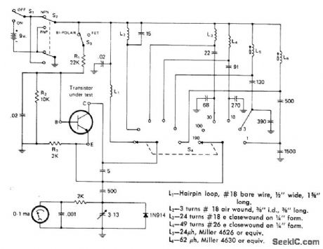
Tells if unknown bipolar or FET transistor is AF, RF, or VHF and whether it is NPN or PNP. Transistor to be tested is placed in frequency-switchable oscillator circuit, and amplitude of oscillation is noted on meter. Highest oscillation frequency corresponds to highest amplification frequency. Six switch positions cover frequency range of 1 to 190 MHz.-F. Brown, An R.F. Transistor Testor, CQ, April 1975, p 35-36 and 66. (View)
View full Circuit Diagram | Comments | Reading(2632)
MEASURING_TRANSISTOR_REVERSE_VOLTAGE_TRANSFER_RATIO
Published:2009/7/17 3:08:00 Author:Jessie
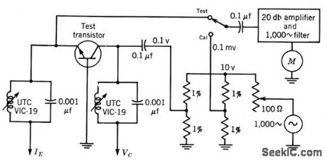
When output voltage is held constant, 10-my scale of output meter gives direct readings of small-signal value of open-circuit reverse-voltage transfer ratio h-rb over range of 0.0001 to 0.001.-Texas Instruments Inc., Transistor Circuit Design, McGraw-Hill, N.Y., 1963, p 72. (View)
View full Circuit Diagram | Comments | Reading(1045)
ADJUSTABLE_TIMER
Published:2009/7/11 1:05:00 Author:May
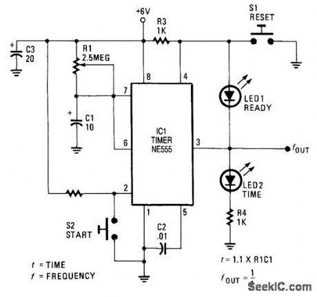
LEDs indicate at a glance what the status of the circuit is al any given moment. Once the reset switch, S1, makes contact, the timer remains in that state until the start switch, S2, is pressed. When either switch is activated, LED1 (ready) and the time indicator, LED2, keep track of the situation. Although not necessary, the two LEDs should be of different colors (for example, red for ready and green for time ). (View)
View full Circuit Diagram | Comments | Reading(915)
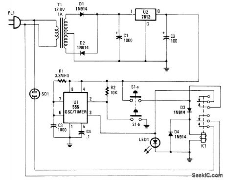
10_MINUTE_ID_TIMER
Published:2009/7/11 1:00:00 Author:May

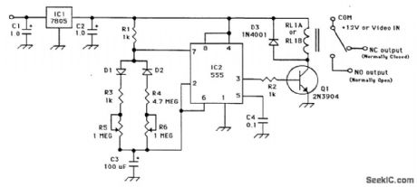
Designed to automatically identify a transmitter every 10 minutes, this 555 circuit has adjustable charge and discharge paths. The IC should be a standard 555 type, not a CMOS type. C3 should be tanta-lum. The relay is a small 5-V reed type. (View)
View full Circuit Diagram | Comments | Reading(1289)
SCR_TIMER
Published:2009/7/11 0:58:00 Author:May
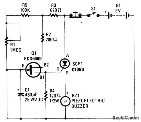
Depending on the R1 (adjustable) C1 time con-stant, when C1 charges up to a certain level, Q1 conducts, triggers SCR1, and sounds BZ1. A push-button resets the circuit. (View)
View full Circuit Diagram | Comments | Reading(784)
APPLIANCE_CUTOFF_TIMER
Published:2009/7/11 0:58:00 Author:May

Suitable for cutting off an appliance or other ac load, this timer will cut the ac power after a period determined by R1/C3, as shown, for about 40 minutes. K1 is a relay that should handle about 10 A. S1A and S1B is a momentary switch that starts the timer cycle. (View)
View full Circuit Diagram | Comments | Reading(1065)
PROGRAMMABLE_TIMER_FOR_LONG_INTERVALS
Published:2009/7/11 0:56:00 Author:May
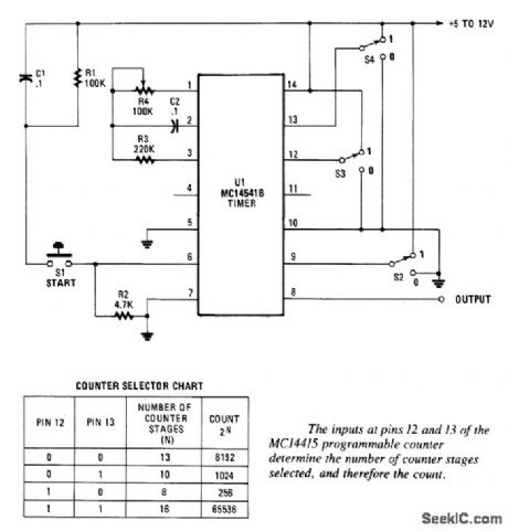
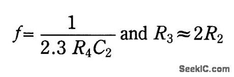
By using an RC oscillator and a programmable divider, this counter can run for hours. An interval oscillator runs at a frequency given by (see figure schematic):By using, for example, R4 = 390 kΩ and C2 = 10 μF and Rz, the oscillator can run at 0.1 Hz. Divided by 65536, this is a cycle of approximately 655 000 s (182 hours, slightly more than a week). (View)
View full Circuit Diagram | Comments | Reading(1830)
LONG_INTERVAL_PROGRAMMABLE_TIMER
Published:2009/7/11 0:53:00 Author:May
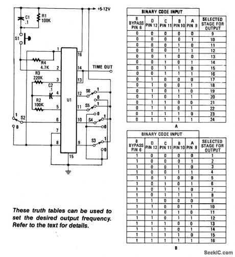
Using an RC oscillator, an up to 24-stage ripple counter (÷) 16777216 or 224, and a 0.1-Hz count-rate with R=39 kΩ, C2 =0.001 μF, and R4-220 k0 for example, the count cycle would take about 654 s. This example shows the capabilities of this time circuit, using the Motorola MC14536 timer. A low-frequency oscillator can be used for longer time periods. (View)
View full Circuit Diagram | Comments | Reading(1801)
TRANSMIT_TIME_LIMITER
Published:2009/7/11 0:51:00 Author:May
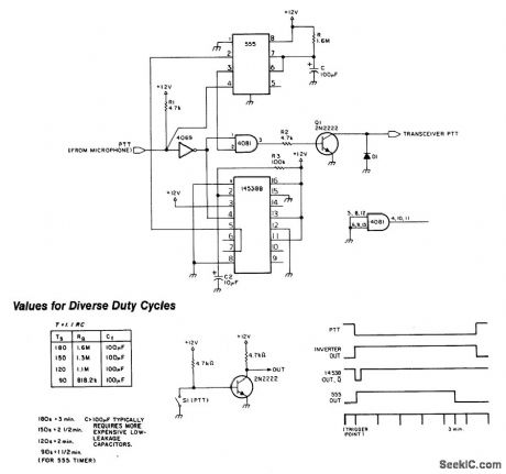
This circuit prevents making transmissions that are too long, which time out repeaters and/or tie up a communications channel too long. On transmit, the PTT (push to talk |ipe) from the microphone is at ground. This causes one input of the AND gate (4081) to go high. The 555 is held in the reset mode. An MC1453B monostable multivibrator generates a pulse to the 555 and causes it to produce a gate of length approximately 1.1RC, where R is selected for desired time delay and C is 100 μF. The output of pin 3 of the 555 causes the 4081 gate to go high, turns on Q1, and keys the transmitter. At the end of the cycle (1.1RC), the AND gate will lose one input, which turns off Q1 and unkeys the transmitter. (View)
View full Circuit Diagram | Comments | Reading(1103)
MAINS_POWERED_TIMER
Published:2009/7/11 0:48:00 Author:May
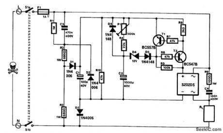
This timer can be inserted in a power line to provide a controllable delay before a load is energized. The mains voltage is reduced'by C3 and rectified to give about 30 V across C1. This potential charges C2 slowly via R4/P1. When UC2 reaches about 14 V, electronic switch T1/T2 actuates a solid-state relay (a Sharp S202DS). When the mains voltage is removed, C2 discharges rapidly via D6 and R10. The delay extends from 15 s (P1 set to minimum resistance) to 5 min (P1 set to maximum resistance).The solid-state relay needs cooling in accordance with the current drawn by the load: at up to 1 A, no heatsink is required; at 1 to 3 A (max), a 5 x 5 cm heatsink is advisable.During the building of the circuit, consideration must be given to safety because many parts will be at mains potential. For instance, fitting the unit in an ABS or other man-made fiber enclosure is a must. If a potentiometer is used for P1, its spindle should be insulated. If a preset is used, it must not be accessible through a hole in the enclosure.Switch S1 is a DPST that disconnects the circuit from the mains. Nevertheless, the only way to safely work on the circuit is to unplug the mains socket and allow C3 sufficient discharge time. (View)
View full Circuit Diagram | Comments | Reading(1028)
THERMAL_MONITOR
Published:2009/7/11 0:27:00 Author:May
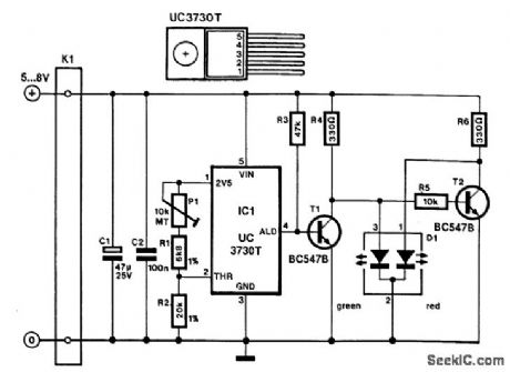
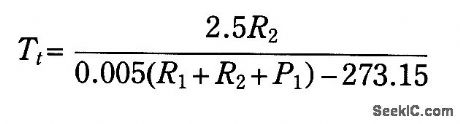
Unitrode's UC1730 family of integrated circuits is designed for use in a number of thermal monitoring applications. Each IC combines a temperature transducer, a precision reference, and a temperature com-parator to allow the device to respond with a logic output if temperatures exceed a predetermined level.The monitor presented here is based on a UC3730T and it is intended to be fitted to a heatsink. Although the supply to the device can be as high as 40 V, 5- to 8-V is chosen here, because it is normally readily available in the equipment where the monitor will be used (power amplifiers, power supplies, etc.).The threshold temperature, Tt, in ℃, is determined by:The temperature can be preset with Pl to values between -1℃ and + 100℃. The indicator is formed by a bicolor LED and controlled by transistors T1 and T2. Resistors R4 and R5 limit the current through the LED. When the temperature of the heatsink is below the threshold temperature, the ALD (alarm delay) output, pin 4, is logic low so that T1 is switched off and the green LED lights. (View)
View full Circuit Diagram | Comments | Reading(1241)
SEALED_COIL_TESTER
Published:2009/7/10 23:54:00 Author:May
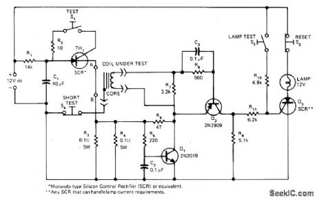
Permits rapid nondestructive testing of hermetically sealed coils for shorted or open turns, coil-to-core shorts, and reversed polarity of connections. Can be used for simultaneous testing of all coils in recording heads for up to 18 tracks. Circuit develops test pulse having predetermined polarity, amplitude, and duration. Article gives details of circuit operation and test procedures. With multiple-coil units, lamp and detector circuit must be provided for each coiL-D. L. Uhls, Novel Method Nondestructively Tests Sealed Coils, EDNMagazine, March 20, 1976, p 102 and 104. (View)
View full Circuit Diagram | Comments | Reading(1518)
TRANSISTOR_DIODE_TESTER
Published:2009/7/10 23:49:00 Author:May
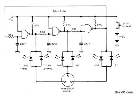
Checks for polarity, shorts, and opens in one measurement, using six LEDs as indicators. Circuit derives three-phasewaveform from 2-kHz ring-of-three oscillator for application to device under test through LEDs. Oscillator waveform serves to make each pair of device terminals forward, reverse, and unbiased in turn for one-third of a cycle. Current flowing into device turns on red LED, and current flowing out turns on green LED, to indicate polarity and position of base lead.-N. E. Thomas, Semiconductor Tester, Wireless World, March 1977, p 43. (View)
View full Circuit Diagram | Comments | Reading(2578)
SIMPLE_RING_DETECTOR
Published:2009/7/10 23:33:00 Author:May
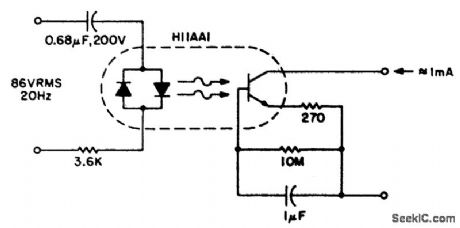
This circuit detects the 20-Hz approximately 86-Vrms ring signal on telephone lines and initiates action in an electrically isolated circuit. Typical applications include automatic answering equipment, interconnect/interface and key systems. The detector is the simplest and provides about a 1-mA signal for a 7-mA line, which loads for 0.1 s after the start of the ring signal. The time-delay capacitor provides a degree of dial-tap and click suppression, and filters out the zero crossing of the 20-Hz wave. (View)
View full Circuit Diagram | Comments | Reading(1291)
±1K_ACCURACY_FOR__55_to_+125℃
Published:2009/7/10 23:23:00 Author:May
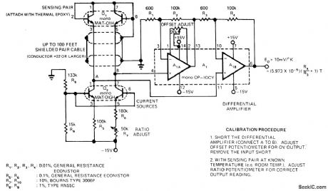
Matched transistor pairs and opamps give highv accuracy temperature-measuring system that is easy to calibrate, has long-term stability, and can operate with sensor transistor pair up to 100 feet from rest of circuit. Common-mode rejection at amplifier input is greater than 100 dB. Output voltage is +2.18V at-55℃ (218 K), increasing to +3.98 V at +125℃(398 K).-J. Simmons and D. Soderquist, Temperature Measurement Method Requires No Referencd,EDN Magazine, Aug. 5, 1974, p 78 and 80. (View)
View full Circuit Diagram | Comments | Reading(762)
EDGE_DETECTOR
Published:2009/7/10 23:22:00 Author:May
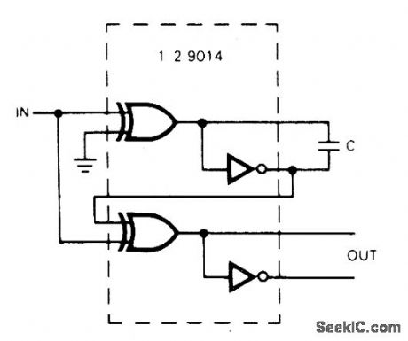
Half of 9014 quad EXCLUSIVE-OR gate serves for generating output pulse for both low-to-high and high-to-low transitions of input signal. Used for regenerating clock in self-clocking pulse-width modulation transmission system, Circuit acts as frequency doublerfor square-wave input. With 1000 pF for C, output pulse width is 70 ns; for 200 pF, width is 30 ns; and when C is 0, width is 10 ns.-Circuits, 73 Magazine, Aug. 1974, p 99. (View)
View full Circuit Diagram | Comments | Reading(0)
0_100℃_WITH_015°ACCURACY
Published:2009/7/10 23:20:00 Author:May
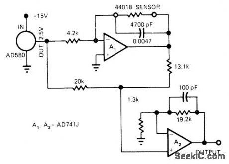
Low-cost YSI44018 temperature sensor in feedback loop of 741J opamp gives accuracy approaching that of platinum sensors. Opamp is driven by AD58O band-gap refelence. Voltage output of A1 feeds similar opamp that provides zeroing and sets desired output gain.-J. Williams, Designer's Guide to: Temperature Measurement,EDN Magazine,May 20,1977,p71-77. (View)
View full Circuit Diagram | Comments | Reading(687)
ASCLL_TO_HEX_CONVERTER
Published:2009/7/10 22:19:00 Author:May
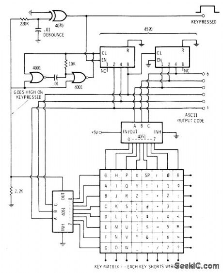
Simple two-chip circuit takes ASCLL data from keyboard and converts characters 0-9 and A-F to 4-bit hexadecimal machine-tanguage format, as required for loading operating system initially into 1802-based microprocessor system. Once loaded, further code conversion can be achieved with software.-E. Copes, 0ne Keyboard: Hex and ASCLL, Kilobaud, June 1978, p 57. (View)
View full Circuit Diagram | Comments | Reading(805)
AIR_VELOCITY_METER
Published:2009/7/10 22:17:00 Author:May
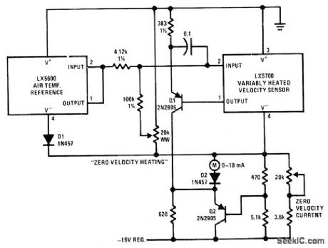
Uses National LX5600 air temperature reference, connected in unitygain mode, in combination with LX5700 selfheated velocity sensor to convert wind velocity or airspeed to differential between heated and unheated transducers. As wind velocity rises, heating current required to hold velocity sensor predetermined number of degrees above ambientis measured. Calibration curve is drawn to show correlation between current and airspeed.-P. Lefferts, A New Interfacing Concept; the Monolithic Temperature Transducer, National Semiconductor, Santa Clara, CA, 1975, AN-132, p 8. (View)
View full Circuit Diagram | Comments | Reading(1696)
SHOCK_SPECTRUM_ANALYZER_WITH_PEAK_VOLTAGE_MEMORY
Published:2009/7/17 4:39:00 Author:Jessie
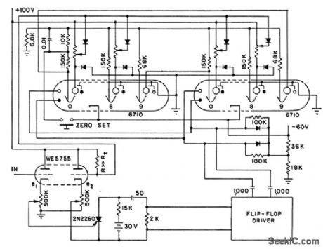
Each peak voltage-memory circuit has frequency-determining L-C filter. Shock spectrum of input pulse is defined by peak voltage across each filter capacitor. Memory is Burroughs Beam-X switching tube in which beam is advanced one position for each voltage increment. Output is d-c voltage suitable for automatic plotting.-Contest Produces Novel Circuit Designs, Electronics, 36:11, p 96-102. (View)
View full Circuit Diagram | Comments | Reading(788)
| Pages:44/101 At 204142434445464748495051525354555657585960Under 20 |
Circuit Categories
power supply circuit
Amplifier Circuit
Basic Circuit
LED and Light Circuit
Sensor Circuit
Signal Processing
Electrical Equipment Circuit
Control Circuit
Remote Control Circuit
A/D-D/A Converter Circuit
Audio Circuit
Measuring and Test Circuit
Communication Circuit
Computer-Related Circuit
555 Circuit
Automotive Circuit
Repairing Circuit