
Index 221
HOME_SECURITY_SYSTEM
Published:2009/7/9 21:45:00 Author:May
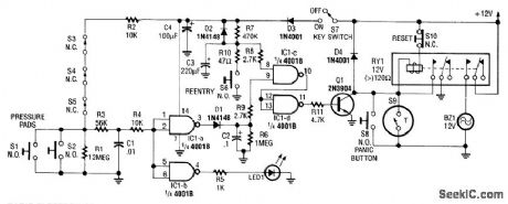
This alarm circuit activates when S1 through S5 are activated. This lights LED1 and activates Q1 via IC1C and IC1D. RY1 is wired to self latch. S10 is used to reset. When key switch S1 is activated or when re-entry buttons at S6 are depressed, IC1C is deactivated until RC network R7/C3 charges. (View)
View full Circuit Diagram | Comments | Reading(1903)
LOGIC_PULSER
Published:2009/7/9 21:42:00 Author:May
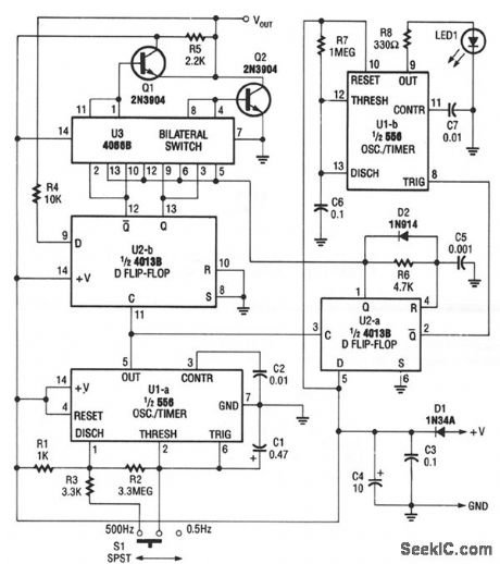
The pulser generates pulses at a user-selected frequency of 0.5 or 500 Hz, with a pulse width of about 5 ms. If the input to be pulsed is already being driven high or low by another output, the pulser automatically pulses the input to the opposite logic state. The pulser is powered by the circuit under test, and operates from supplies of from + 5 to + 15 Vdc. (View)
View full Circuit Diagram | Comments | Reading(2184)
INDUCTANCE_BRIDGE
Published:2009/7/9 21:25:00 Author:May

This bridge will measure inductances from about 1 to 30 μH at a test frequency of 5 mHz. A 365-pF AM-type tuning capacitor is used as a variable element. The circuit should be constructed in a metal enclo-sure. Calibration can be done on known inductors or by plotting a curve of the capacitance of the 365-pF capacitor versus rotation and calculating the inductance from this. The range of measurement can be charged by using a different frequency crystal and/or variation of L2 and C6. (View)
View full Circuit Diagram | Comments | Reading(869)
AIR_FLOW_SENSING_THERMISTOR_BRIDGE
Published:2009/7/9 21:20:00 Author:May
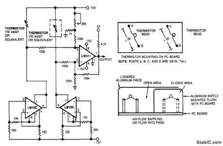
Using the thermistor-bridge circuit, you can detect system-cooling air losses caused by filter or inlet blockage or fan failure. One thermistor is mounted directly in the air flow; the other is baffled. The exposed thermistor senges the temperature in the cooling system; the baffled thermistor senses the ambient temperature in still air. As long as the thermistors are at different temperatures, the bridge stays unbalanced and the circuit produces a logical high, indicating that the cooling system is working. If the air flow stops, the exposed thermistor will reach ambient temperature, the bridge will become balanced, and the circuit will indicate ventilation-system failure by producing a logical low.
The bridge circuit's matched thermistors are biased 'oy matched-current sources. Two LM10C operational, amplifiers act as constant-current sources, and an LM311 comparator senses the difference between the voltage drops across the thermistors, producing the logical high when the bridge is unbal-anced and the logical low when the bridge is balanced. Use a 20-kΩ potentiometer to set the comparator's threshold; this setting determines the minimum air flow that will cause the circuit to produce a logical high. (View)
View full Circuit Diagram | Comments | Reading(1869)
AC_CIRCUIT_BREAKER
Published:2009/7/9 21:19:00 Author:May
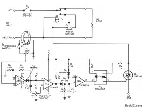
The adjustable circuit breaker responds in 0.02 s under all conditions-provided you select a fast relay for K1. For moderate overload conditions, it's preferable to use the fuse or the fast-acting breaker. Toroid transformer T1 senses ac load current and produces an ac signal at the wiper of R1, when switch S3 is closed. Diode D1 rectifies this signal to produce a positive voltage at test point TP1. Because R1 allows you to calibrate this voltage, the circuit accommodates a variety of current-sense transformers. To calibrate the trip threshold, apply the maximum expected overload and adjust R1 until the TP1 voltage is 0.7 V below the positive saturation level for IC1. Then adjust R4 for the desired trip point. To reset the circuit breaker after it has tripped, open S1 or S2. (View)
View full Circuit Diagram | Comments | Reading(2325)
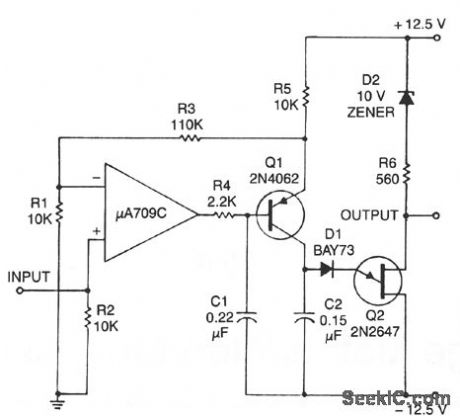
ELECTRIC_CROWBARS
Published:2009/7/9 21:13:00 Author:May

To avoid grief when using 12-V power supplies with mobile transceivers, especially when there is a short-circuit failure of the series pass transistor, crowbar circuits provide protection by clamping the power line and blowing the fuse within microseconds of an overvoltage condition. It is a good idea to incorporate the crowbar directly into the transceiver. The main difference between the two circuits is that less complex circuit B depends on component tolerances for the exact trigger level, while the circuit A includes a unijunction trigger to permit precise setting of the operating point. (View)
View full Circuit Diagram | Comments | Reading(987)
VOLTAGE_TO-FREQUENCY_CONVERTER_1
Published:2009/7/9 21:04:00 Author:May
This circuit consists of a UJT oscillator in which the timing charge capacitor C2 is linearly dependent on the input signal voltage. The charging current is set by the voltage across resistor R5, which is accurately controlled by the amplifier. (View)
View full Circuit Diagram | Comments | Reading(637)
BATTERY_VOLTAGE_MEASURING_REGULATOR
Published:2009/7/9 21:01:00 Author:May
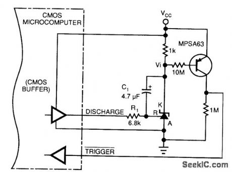
This circuit allows a microprocessor system to measure its own battery voltage. A Texas Instrument 71431 precision shunt regulator acts as a precision reference and integrator/amplifier, measuring its own supply via voltage-dependent charge/discharge time intervals. Notice that you must write a short control and voltage calculation software routine for your system. (View)
View full Circuit Diagram | Comments | Reading(738)
ACCURATE_VOLTAGE_TO_FREQUENCY_CONVERTER
Published:2009/7/9 21:01:00 Author:May
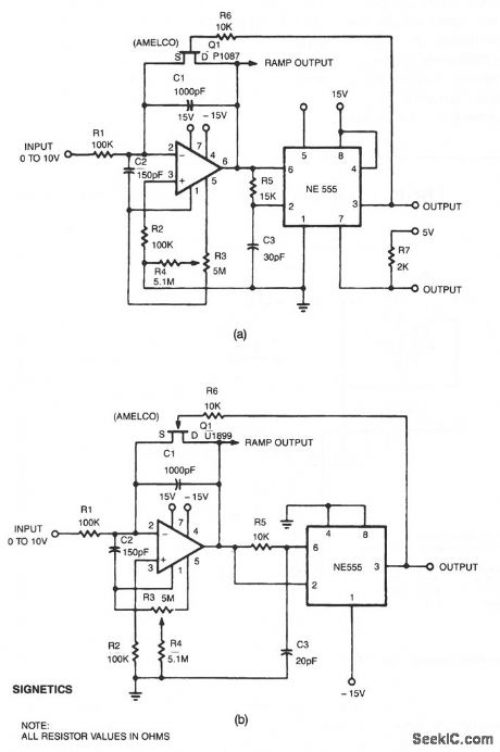
This linear voltage-to-frequency converter.a. achieves good linearity over 0 to -10 V. Its mirror image b. provides the same linearity over 0 to + 10 V, but it is not DTL/TTL compatible. (View)
View full Circuit Diagram | Comments | Reading(719)
BATTERY_TEMPERATURE_SENSING_NICAD_CHARGER
Published:2009/7/9 20:58:00 Author:May
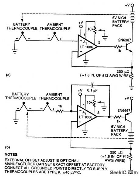
Two simple circuits permit Nicad charging of a battery based on temperature differences between the battery pack and the ambient temperature. This method has the advantage of allowing fast charging because the circuit senses the tempera-ture rise that occurs after charging is complete and the battery under charge is producing heat, not accumulating charge. (View)
View full Circuit Diagram | Comments | Reading(840)
IR_REMOTE_EXTENDER
Published:2009/7/9 20:57:00 Author:May
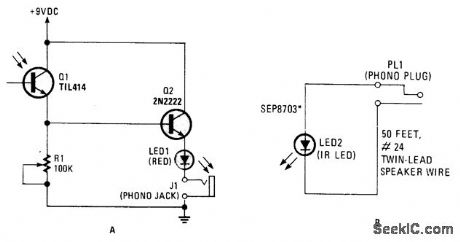
This circuit can be used to operate a VCR or CD player from another room. It's really an infrared signal repeaten The signal from the remote is received and then retransmitted over wires to an infrared LED. The beam from the LED is then picked up by the receiving window on the VCR or CD player.
The visible light LED (LED1) in series with the IR unit (LED2) is used to indicate that the transmit-ted signal has been detected. The 100-kΩ trimmer potentiometer (R1) adjusts the repeater's sensitiity.The resistor that is usually found in series with the LEDs is omitted, because the voltage reading is about 1.0 Vdc as a result of the voltage drop across the lines. (View)
View full Circuit Diagram | Comments | Reading(995)
RF_PROBE_1
Published:2009/7/9 20:57:00 Author:May
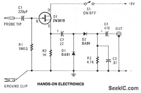
Transistor Q1-conftgured as a source-follower buffer stage, offering a bit under unity voltage gain-gives the unit a high-impedance input of about 1 MΩ shunted by about 10 pF, which keeps only minimal loading on the equipment being tested. C1 serves as input dc blocking capacitor. The Q1 output is coupled by C2 to a simple AM detector circuit made up of D1, D2, R3 and C3. Capacitor C4 provides output dc blocking. Total current consumption should be somewhere around 1 mA. The circuit responds to frequencies from 100 kHz to well over 50 MHz. (View)
View full Circuit Diagram | Comments | Reading(1124)
DIGITALLY_SELECTABLE_INPUTS_AND_GAIN
Published:2009/7/9 20:52:00 Author:May
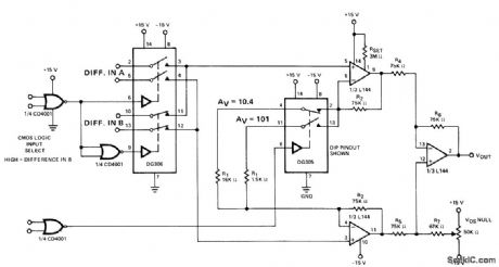
Low-power DG306 and DG305 analog switehes provide choice of 10.4 or 101 gain and choice of two differential input channels for instrumentation applications. Highest gain is obtained when control logic is high.- Analog Switches and Their Applications,''siliconix,Santa Clara,CA,1976,p 7-91. (View)
View full Circuit Diagram | Comments | Reading(786)
FET_PROBE
Published:2009/7/9 20:47:00 Author:May
This FET probe has an input impedance of 10 MΩ shunted by 8 pF. Eliminating the protective diodes reduces this impedance to about 4 pF. The frequency reiponse of the probe extends from dc to 20 MHz (-1 dB), although higher frequency operation is possible through optimized construction and use of a UHF-type transistor. Zero dc offset at the output is achieved by selecting a combination of a 2N5246 and source resistor that yields a gate-source bias equal to the Pjyg of the 2N3704 at approximately 0 V. At medium frequencies, the probe can be used unterminated for near-unity gain; for optimum impedance converter probe high-frequency response, the cable must be terminated into 50 Ω. The voltage gain, when properly terminated, is precisely 0.5 X. (View)
View full Circuit Diagram | Comments | Reading(3591)
IR_HEAT_CONTROLLED_KITCHEN_FAN
Published:2009/7/9 20:45:00 Author:May
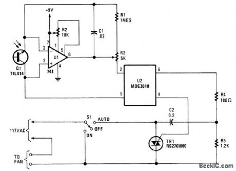
Q1 senses IR from heat sources, causes U1 to switch, activates optocopuler U1, and triggers TR1.This controls a fan. The Triac is from Radio Shack, or else a 200-V, 6-A unit (C106B) can be used. (View)
View full Circuit Diagram | Comments | Reading(928)
BATTERY_POWERED_GROUND_NOISE_PROBE
Published:2009/7/9 20:44:00 Author:May
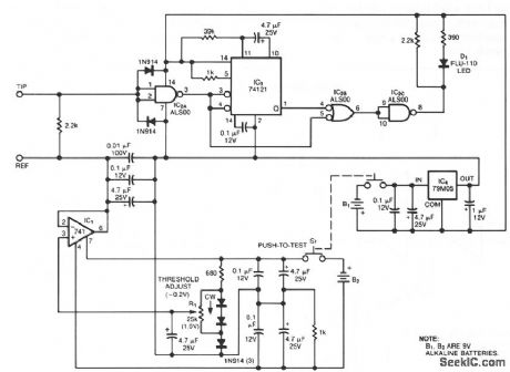
Oscilloscope measurements of ground noise can be unreliable because noise can enter your circuit via the scope's three-pronged power plug. You can avoid this problem by using the ground-noise tester shown. Powered by two 9-V batteries, the circuit dissipates power only while push-to-test switch S1 is depressed. Noise pulses that reach IC2A's switching threshold of about 1.5 to 1.8 V create a logic transition that triggers the monostable multivibrator IC3, which stretches the pulse to produce a visible blink from LED D1.You set the noise reference level by adjusting threshold-adjust potentiometer R1, which lets the circuit respond to minimum pulse amplitudes ranging from about 0 to 1 V. For convenience, you can use a one-turn potentiometer for R1 and calibrate the dial by applying an adjustable dc voltage, monitored by an accurate voltmeter. (View)
View full Circuit Diagram | Comments | Reading(744)
4_220_V_TEST_PROBE
Published:2009/7/9 20:42:00 Author:May
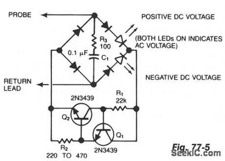
Using inexpensive components, you can fit a simple probe circuit into a pencil-sized enclosure. When both LEDs are on, the probe indicates the presence of an ac voltage; either LED alone indicates the presence and polarity of a dc voltage. The diode-bridge arrangement allows one-way current source R1, R2, Q1, and Q2 to light either LED (or both) when the probe is activated by a test voltage. Diodes, provide the necessary peak-inverse voltage rating; R3 and C1 provide a spike-suppression network to protect the current-source transistors. (View)
View full Circuit Diagram | Comments | Reading(1030)
CMOS_UNIVERSAL_LOGIC_PROBE
Published:2009/7/9 20:40:00 Author:May
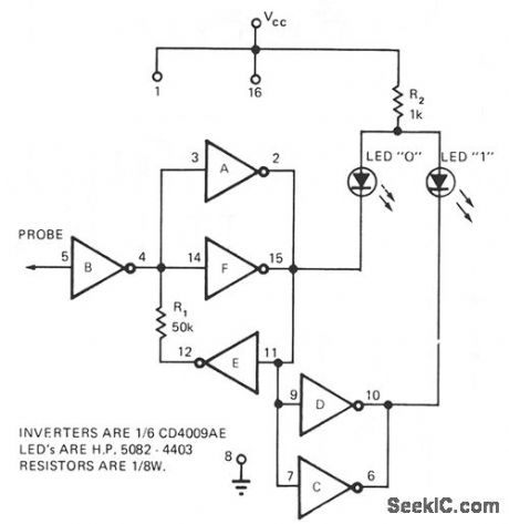
Only the CD4009AE hex buffer, two resistors, and two LEDs are required for a logic probe. CMOS logic probe features 1012Ω input impedance and covers 3 to 15 V range. While LEDs are visible at all voltages, a 1-KΩ pot in place of R2 will allow the user to increase brightness at lower voltages. (View)
View full Circuit Diagram | Comments | Reading(662)
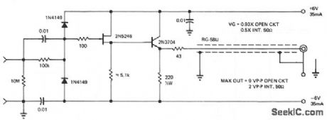
RF_PROBE
Published:2009/7/9 20:38:00 Author:May
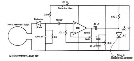
This rt probe is coupled with a fiber-optic cable to the test equipment. It utilizes inexpensive components to improve probe performance at UHF frequencies. The receiving antenna in this probe feeds an envelope-detector diode. After amplification by the LF356 op amp, the low-frequency output modulates the LED, which in turn feeds the optical fiber. The design facilitates the use of a single battery for the op amp, with voltage splitting by means of the 1-KΩ potentiometer, and miniature 47-μF tantalum capacitors to provide decoupling. The gain control is easily adjusted to give the best dynamic range for a specific LED. (View)
View full Circuit Diagram | Comments | Reading(3236)
IR_CONTROLLED_SOLDERING_STATION
Published:2009/7/9 20:35:00 Author:May
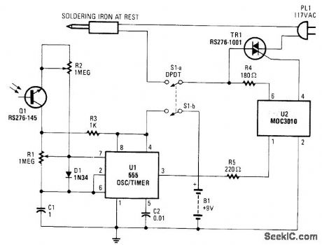
An IR-sensitive phototransistor is used to sense soldering-iron temperature. The phototransistor must see the tip through an opaque tube to avoid stray light, and the phototransistor should preferably be fitted with an IR filter. An old photo negative, dark red plastic, or red or black glass can be used. The iron sits on a holder.
When the iron is removed from the holder, the iron is not being viewed by the detector. The heat will increase, but the circuit has a lag time; if the iron is returned to its holder after each use, overheating should not be a problem. (View)
View full Circuit Diagram | Comments | Reading(3250)
| Pages:221/471 At 20221222223224225226227228229230231232233234235236237238239240Under 20 |
Circuit Categories
power supply circuit
Amplifier Circuit
Basic Circuit
LED and Light Circuit
Sensor Circuit
Signal Processing
Electrical Equipment Circuit
Control Circuit
Remote Control Circuit
A/D-D/A Converter Circuit
Audio Circuit
Measuring and Test Circuit
Communication Circuit
Computer-Related Circuit
555 Circuit
Automotive Circuit
Repairing Circuit