
Index 238
THREE_CHIP_EKG_SIMULATOR
Published:2009/7/8 2:06:00 Author:May
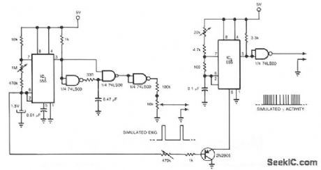
Two 555s and a quad NAND-gate IC can simulate an electrocardiograph signal and a γ-wave radioisotope signal for applications in nuclear medicine. This circuit synchronizes the radioisotope signal to the EKG signal. You can use the circuit's outputs to test, for example, microprocessor-based software that calculates the left ventricular ejection fraction before you use the software in clinical applications. IC1, a 555 timer, provides a positive-going pulse train that simulates an EKG signal. A 10-KΩ potentiometer provides frequency adjustment. The other 555 timer, configured as a pulse-position modulator, provides the simulated γ-wave activity. (View)
View full Circuit Diagram | Comments | Reading(1104)
OPTICAL_PICK_UP_TACHOMETER
Published:2009/7/8 2:00:00 Author:May
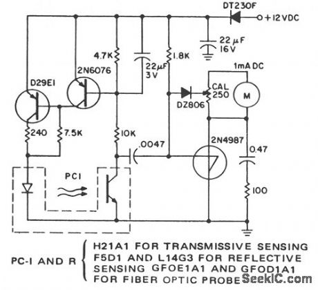
Remote, noncontact, measurement of the speed of rotating objects is the purpose of this simple circuit. Linearity and accuracy are extremely high and normally limited by the milliammeter used and the initial calibration. This circuit is configured to count the leading edge of light pulses and to ignore normal ambient light levels. It is designed for portable operation since the tachometer is not sensitive to supply voltage within the supply voltage tolerance. Full scale at the maximum sensitivity of the calibration resistance is read at about 300 light pulses per second. A digital voltmeter can be used, on the 100-mV full-scale range, in place of the milliammeter. Shunt its input with a 100-Ω resistor in parallel with a 100-μF capacitor. This rc network replaces the filtering supplied by the analog meter.
(View)
View full Circuit Diagram | Comments | Reading(999)
SIMPLE_LINEAR_THERMOMETER
Published:2009/7/8 1:59:00 Author:May
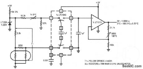
The thermistor network specified eliminates the need for a linearity trim-at the expense of accuracy and operational range. (View)
View full Circuit Diagram | Comments | Reading(554)
IMPLANTABLE_INGESTIBLE_ELECTRONIC_THERMOMETER
Published:2009/7/8 1:55:00 Author:May
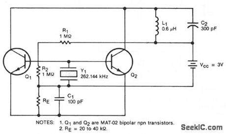
This oscillator circuit includes a quartz crystal that has a nominal resonant frequency of 262,144 Hz and is cut in the orientation that gives a large linear coefficient of frequency variation with the temperature.In this type of circuit, the oscillation frequency is controlled primarily by the crystal-as long as the gain-bandwidth product is at least four times the frequency. In this case, the chosen component values yield a gain-bandwidth product of 1 MHz. Inductor L1 can be made very small: 100 to 200 turns with a diameter of 0.18 in. (4.8 mm) and a length of 0.5 in. (12.7 mm). Although the figure shows two transistors in parallel, one could be used to reduce power consumption or three could be used to boost the output. The general oscillator circuit can be used to measure temperatures from -10 to + 140 °C. A unit made for use in the human body from about 30 to 40 °C operates at 262,144 ± 50 Hz with a frequency stability of 0.1 Hz and a temperature coefficient of 9 Hz/°C. (View)
View full Circuit Diagram | Comments | Reading(850)
10_W_MARINE_BAND
Published:2009/7/8 1:53:00 Author:May
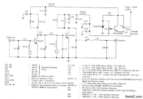
Power amplifier operating in class C from 12.5-VDC supply is designed for 152-162 MHz VHF marine band. Switch permits reducing power output to 1W or less. Tuning range of 144-175 MHz makes amplifier suitable for other applications such as amateur 2-meter and Iand-mobile radio. Power input is 181mW, power gain is 17.4dB, and effieiency is 44.5%.-J. Hatchett, 25-Watt and 10-Watt Marine Band Transmitters, Motorola, Phoenix, AZ, 1978, AN-595, p 4. (View)
View full Circuit Diagram | Comments | Reading(1385)
LOW_CURRENT_MEASUREMENT_SYSTEM
Published:2009/7/8 1:50:00 Author:May
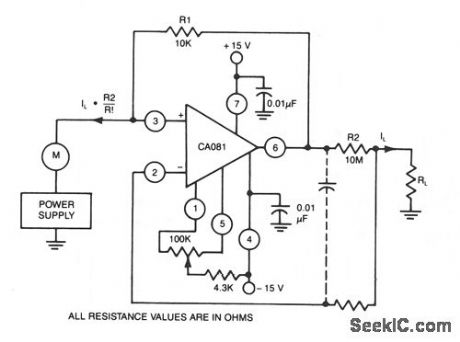
This circuit uses a CA018 BiMOS op amp. Low current, supplied at input potential as power supply to load resistor RL, is increased by R2/R1, when load current IL is monitored by power supply meter M. Thus, if IL is 100 rA, with values shown, IL presented to supply will be 100 ph. (View)
View full Circuit Diagram | Comments | Reading(758)
DIFFERENTIAL_TO_10°F
Published:2009/7/8 1:45:00 Author:May
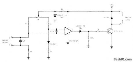
Simple circuit senses difference between temperatures of two objiects, as required for such control applications as turning on fans, turning off heaters, or opecrating mixing valves, inexpensive 1N4001 silicon diode is used as sensor; with two such diodes in resistance bridge as shown, voltage between reference and sensor diodes is applied to pins 4 and 7 of opamp. High-gain opamp is required because bridge output is only about 2mV/℃ of temperature differential. If output requires morethan about 10 mA, buffer transistor is needed.-J. Barnes, Differential-Tempera-ture Sensor is Very Inexpensive, EDN Magazine, April5, 1973, p 90-91. (View)
View full Circuit Diagram | Comments | Reading(497)
HOT_WIRE_ANEMOMETER
Published:2009/7/8 1:43:00 Author:May

View full Circuit Diagram | Comments | Reading(3180)
TEMPERATURE_REPORTING_DIGITAL_THERMOMETER
Published:2009/7/8 1:42:00 Author:May
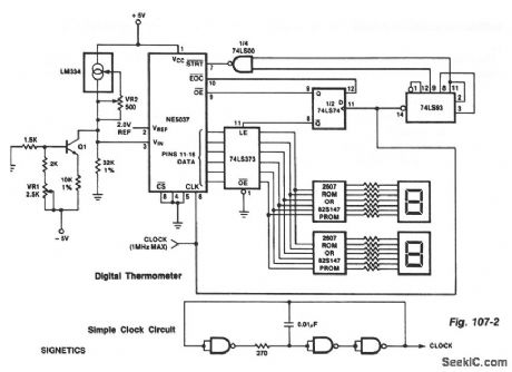
The ROMs or PROMs must have the correct code for converting the data from the NE5037-used as address for the ROMs or PROMs-to the appropriate segment driver codes. The displayed amount could easily be converted to degrees Fahrenheit, °F, by the controller of (0 - 63 °temperature sensor) or through the (P) ROMs. When doing this, a third (hundreds) digit (P)ROM and display will be needed for displaying temperatures above 99 °F. An expensive clock can be made from NAND gates or inverters as shown. (View)
View full Circuit Diagram | Comments | Reading(1206)
0001°C_ACCURACY
Published:2009/7/8 1:36:00 Author:May
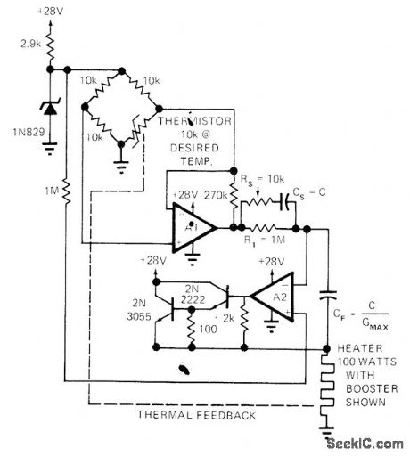
Simple design using thermistor bridge and two opamps controls temperature with high precision and has wide dynamic response as required for fast-changing ambient conditions. Circuit will not oscillate about desired temperature. Article covers design and operation of circuit in detail.-L. Accardi, Universal Temperature Controller, EDN Magazine, Dec. 1, 1972, p 53 and 55.
(View)
View full Circuit Diagram | Comments | Reading(815)
DIFFERENTIAL_THERMOMETER
Published:2009/7/8 1:18:00 Author:May
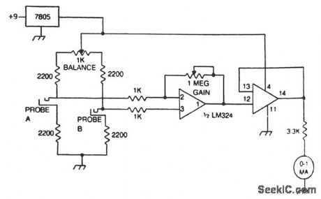
The differential thermometer uses two probes and shows the temperature difference between them, rather than the exact temperature. The thermometer uses a conventional meter as an indicator, and it covers a total range of 20 ° - 10 °low to 10 °high. (View)
View full Circuit Diagram | Comments | Reading(4377)
TESLA_COIL
Published:2009/7/8 1:11:00 Author:May
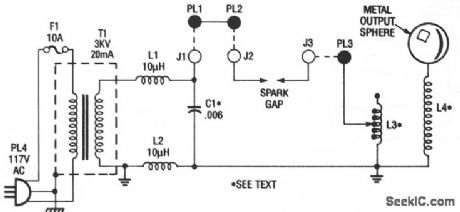


Power is fed to transformer T1, a small neon-sign transformer, which steps the voltage up to about 3000 Vac. The stepped-up output of T1 is fed through L1 and L2 and across C1, causing the capacitor to charge until enough power is stored in the unit to produce an arc across the spark gap. The spark gap, which momentarily connects C1 and L3 in parallel, determines the amount of current transferred between C1 and L3.The arcing across the spark gap sends a series of high-voltage pulses through L3, giving a sort of oscillated effect. The energy fed through L3 is transferred to L4 via the magnetic coupling between the two coils. Because of the turn ratio that exists between L3 and L4, an even higher voltage is produced across L4. Coil L4 steps up the voltage, which collects on the top-capacitance sphere. There, it causes an avalanche breakdown of the surrounding air, giving off a luminous discharge.The rotary spark gap is a simple add-on circuit for the Tesla Coil, consisting of a variable dc power supply and a small, 5000-rpm, dc motor. The circuit allows you to vary the output of the Tesla coil by adjusting the rotating speed of the motor. A rotary gap is far more efficient than a stationary gap, because the stationary gap could cut-out and require readjustment. (View)
View full Circuit Diagram | Comments | Reading(1948)
160_W_LINEAR_SSB
Published:2009/7/7 23:48:00 Author:May
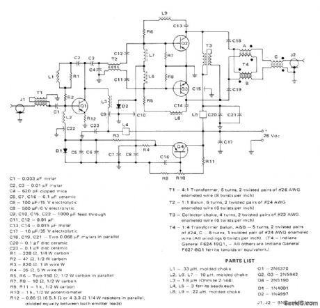
Designed for operation at fixed land location, using 28-VDC supply. Circuit covers 3-30 MHz band, using driver stage to providetotal power gain of about 30 dB, lf heatsinks are used, cooling fans are not normally re-quired because average power for speech operation is about 15 dB below peak levels.-H.Granberg, Broadband Linear Power Amplifiers Using Push-Pull Transistors, Motorola, Phoenix, AZ, 1974, AN-593, p 3. (View)
View full Circuit Diagram | Comments | Reading(764)
THERMOCOUPLE_MULTIPLEX_SYSTEM
Published:2009/7/7 23:33:00 Author:May
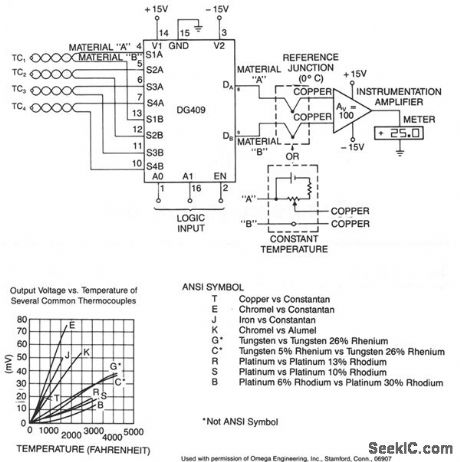
ANSI SYMBOL T Copper vs Constantan E Chromet vs Constantan J Iron vs Constantan K Chrornel vs Alumel G Tungsten vs Tungsten 26%Rhenium c TUNgsten 5% Rhenium vs Tungsten 26%Rhenium R Platlnum vs Platinum 13%Rhodium S Platinum vs Platinum 10%Rhodium B Platinum 6% Rhodium vs Platinum 30% Rhodium
Not ANSI Symbol
To decouple the sensors from the meter amplifter, either a reference junction at 0°C or a bucking voltage set at room temperature may be used. The latter method is simpler, but is sensitive to changes in ambient temperature The table above shows the output voltage vs temperature of several colmmon types of thermocouples. (View)
View full Circuit Diagram | Comments | Reading(969)
455_kHz_WITH_PRODUCT_DETECTOR_AND_BFO
Published:2009/7/7 23:32:00 Author:May

Used in 1.8-2 MHz communication receiver having wide dynamic range. Input comes from diode-switched bandpass filter giving choice of 400-Hz or 2.1-kHz bandwidths. Output for AGC amplifier is taken from primary of T3.AGO voltage, ranging from +2 V for minimum gain to +9 V for maximum gain, is applied to pins 7 of both IF opamps. Product detector uses quad 1N914A diodes. Varicap CR10 and R1 vary BF0 output from 453 to 457 kHz. Two-part artide gives all other circuits of receiver.-D.DeMaw, His Eminence-the Receiver, QST, Part 2-July 1976, p 14-17 (Part 1-June 1976, p 27-30). (View)
View full Circuit Diagram | Comments | Reading(1901)
LEVEL_SHIFTER_WITH_HIGH_CURRENT_DRIVE
Published:2009/7/7 23:31:00 Author:May
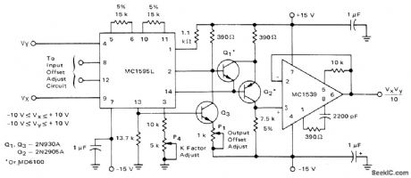
Motorola MC1539 opamp is used as source-follower output stage for three-transistor llevel shifter of MC1595L Iinear four-quadrant multiplier, to improve current drive capabilities. 0utput voltage is in range of ±10 V. Input offset adjusting circuits are 10K pots in series with 10K resistors between ±15 V, with 1K to ground from each side of paralleled pots.-E. Renschler, Analysis and Basic Operation of the MC1 595, Motorola, Phoenix, AZ, 1975, AN-489 p11. (View)
View full Circuit Diagram | Comments | Reading(859)
FOUR_OUADRANT_MULTIPLIER_SQUARER
Published:2009/7/7 23:26:00 Author:May
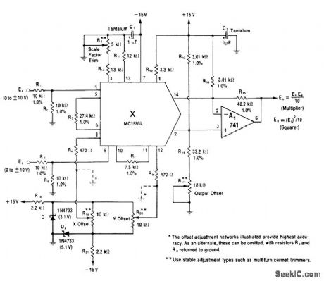
Basic1595 multiplier block and 741 current-to-voltage converter convert input voltages Ex and Ey to output equal to one-tenth of their product when connected as shown for multiplier use. To operate as squarer of Ex, connect pins 4 and 9 together and omit R5 and R6 at Ey input. Output is then one-tenth of square of Ex.-W. G. Jung, IC Op-Amp Cookbook, Howard W. Sams, Indianapolis, IN, 1974, p 255-257. (View)
View full Circuit Diagram | Comments | Reading(671)
ELECTRONIC_HEAT_SNIFFER_
Published:2009/7/7 23:23:00 Author:May

Sensing element Q1 is a 2N3904 general-purpose npn transistor, although any general-purpose npn unit in a TO-92 style case will do. IC1, an LM334, supplies Q1 with a constant current that is independent of temperature. An LM324 quad op amp, IC2, forms a high input-impedance differential amplifier (IC2a, IC2b, and IC2c) with a gain of about 99. IC2d is used as a voltage comparator. When Q1 senses a rise or fall in temperature, the base-to-emitter voltage decreases. That decrease in voltage causes the input to IC2a at pin 3 to deviate from the reference voltage that's fed to IC2b at pin 5, which is set by potentiometers R5. The difference between the input and the reference is amplified by IC2c. That amplified voltage is fed to IC2d where it is compared to a control voltage set by potentiometer R13. The setting of R13 determines the threshold and is set at a point that's equal to the ambient temperature. The output of IC2d at pin 14 is fed to the base of transistor Q2. When the output of IC2d is high, LED1 lights and Q2 turns on. With Q2 turned on, a ground path through the transistor is provided for buzzer PB1.The circuit can be built on perforated construction board using point-to-point wiring. All components, except Q1, are mounted on the board. Transistor Q1 is mounted at the tip of the heat-sensing probe. (View)
View full Circuit Diagram | Comments | Reading(1212)
APPROXIMATING_ARC_TANGENTS
Published:2009/7/7 23:22:00 Author:May
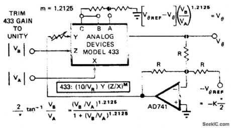
Analog Devices 433 multiplier/divider IC approximates arc tangent to 0. 75% Article presents mathematical basis for approximation used.-D.H Sheingold, Approximate Analog Functions with a Low-cost Multiplier/Divider.EDN Magazine,Feb,5.1973,p50-52. (View)
View full Circuit Diagram | Comments | Reading(670)
SQUARING_FOR_RMS
Published:2009/7/7 23:17:00 Author:May
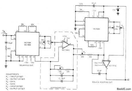
Combination of two MC1594 multipiiers and two opamps gives RMS detector for squaring instantaneous input values, averaging over time interval, then taking square root to give RMS value of input wave-form. First multiplier, used to square input waveform, delivers output current to first opamp for conversion to voltage and for aver-aging by means of capacitor in feedback path. Second opamp is used with second multiplier as feedback element for taking square root. Technique eliminates thermal response time drawback of most other RMS measuring circuits. Input voltage range for circuit is 2 to 10 V P-P; for other ranges, input scaling can be used. Since direct coupling is used, output voltage in. dudes DC components of input. Maximum input frequency is about 600 kHz, and accuracy is about 1%,-K. Huehne and D. Aldridge, True RMS Measurements Using IC Multipliers, EDN Magazine, March 20, 1973, p 85-86. (View)
View full Circuit Diagram | Comments | Reading(898)
| Pages:238/471 At 20221222223224225226227228229230231232233234235236237238239240Under 20 |
Circuit Categories
power supply circuit
Amplifier Circuit
Basic Circuit
LED and Light Circuit
Sensor Circuit
Signal Processing
Electrical Equipment Circuit
Control Circuit
Remote Control Circuit
A/D-D/A Converter Circuit
Audio Circuit
Measuring and Test Circuit
Communication Circuit
Computer-Related Circuit
555 Circuit
Automotive Circuit
Repairing Circuit