
Circuit Diagram
Index 155
Miniature Black and White TV System
Published:2013/3/10 22:52:00 Author:Ecco | Keyword: Miniature Black , White TV System

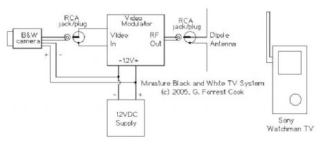
The camera's video signal is connected to the video modulator with an RCA jumper cable. Power to the camera and video modulator is connected to the 12V power supply. Be careful with polarity, reversing the leads may damage the modulator. The camera that was used had reverse polarity protection built in. The modulator's RF output signal is connected to a small antenna, the antenna can be made with two short lengths of #16 gauge solid wire. Alternately, for long distance wired operation, the RF signal can be fed into a length of 75 ohm coax cable with a 75 ohm terminating resistor across the far end of the cable. Connect the remote center conductor of the cable to the TV antenna through a 330 ohm resistor.
(View)
View full Circuit Diagram | Comments | Reading(2686)
CDV700 Geiger Counter Probe Rebuilding
Published:2013/3/10 22:50:00 Author:Ecco | Keyword: Geiger Counter, Probe Rebuilding
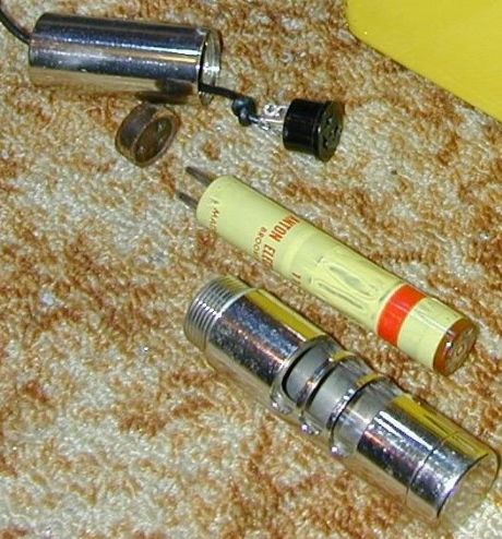
This article describes the process of rebuilding a geiger counter probe from the Victoreen CDV700 geiger counter. The process of converting the hard-wired probe to a probe with a pluggable BNC connector is also described. The probe from the model CDV700-6B is similar, but not identical, the socket is easier to access on that model.
(View)
View full Circuit Diagram | Comments | Reading(867)
Count Accumulator for Radiation Levels (CARL)
Published:2013/3/10 22:49:00 Author:Ecco | Keyword: Count Accumulator, Radiation Levels , CARL
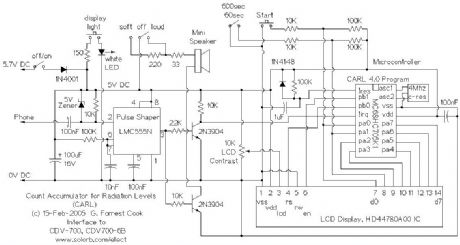
The CARL device is an add-on numerical counter that plugs into the headphone jack of 1960s vintage geiger counters such as the Victoreen CDV700 and CDV700-6B. It should also work with the Lionel ENI/LENi counters, and any other geiger counter that has a headphone output pulse greater than -5V.
Vintage 1960s era geiger counters don't actually count, they use an analog meter with an integrator circuit to give short-term averaged readings of radiation detections (clicks). The CARL circuit keeps track of the total number of clicks for a period of either 60 or 600 seconds (1 or 10 minutes). This provides a way to get a long-running count of low-level radiation from sources such as radon gas, rock samples and background radiation. The CARL circuit allows for the measurement and comparison of radioactive sources that are of levels that don't produce measurable readings on analog geiger counter meters.
In my Colorado location, the CARL counter shows background radiation levels of 15-20 clicks per minute upstairs and 20-25 clicks per minute in basements where radon gas is present.
As a collector of rocks, my interest in making this device was to find all of the radioactive minerals in my collection, and remove them from my living space. I found quite a few rocks that registered above the background level, fortunately, I did not find anything super-hot. I have also used the meter to compare background levels in various geographical locations.
(View)
View full Circuit Diagram | Comments | Reading(1301)
Hot Rodding a CDV700 Geiger Counter
Published:2013/3/10 22:47:00 Author:Ecco | Keyword: Hot Rodding, Geiger Counter
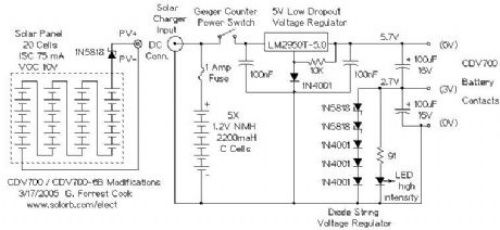
The original power supply for the CDV700 and CDV700-6B uses two pairs of D cell batteries. The 3V-6V battery set supplies the oscillator circuit with 33ma of current when properly adjusted. The 0V-3V battery set supplies the detector circuit with a few ma of current. This causes the batteries to wear out at different rates.
Conversion to modern NiMH C cells allows the counter to run for longer periods of time. The rechargeable batteries work well with a small solar panel for recharging. A set of 5 AA-size NiMH cells would also work for this application. NiCd cells can also be used, but NiMH cells have higher power density and are generally better batteries.
After six years of occasional use, both of these meters are still running fine on the original NiMH battery sets. The PV panels have been located indoors on sunny window sills.
(View)
View full Circuit Diagram | Comments | Reading(773)
TTL Pulse Reading Logic Probe
Published:2013/3/10 22:46:00 Author:Ecco | Keyword: TTL Pulse, Reading , Logic Probe

This circuit can be built on perforated circuit board and wired by hand. The completed circuit can be assembled into a clear plastic box with the wires protruding out one end. The LEDs should be visible through the box. IC sockets should be used for easy chip replacement.
(View)
View full Circuit Diagram | Comments | Reading(1041)
Octopus Curve Tracer
Published:2013/3/10 22:45:00 Author:Ecco | Keyword: Octopus Curve Tracer
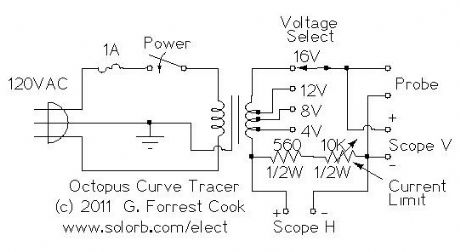
This project involves the construction of a low-cost curve tracer that is suitable for testing a wide variety of electronic components both in-circuit and out of circuit. It is easy to construct and extremely useful for finding defective parts, especially semiconductors, in electronic devices.
The octopus is used in conjuction with an oscilloscope set to display in X-Y mode. It displays voltage across the test probes on one axis and current through the probes on the other axis. A scope with both Horizontal and Vertical inputs (X-Y mode) is required.
This is my version of a circuit that has been around since at least the 1960s, I added the ability to select voltage taps on the filament transformer and adjust the amount of current through the probes.
(View)
View full Circuit Diagram | Comments | Reading(5451)
Frequency Calibrator for AM and Shortwave Radios
Published:2013/3/10 22:42:00 Author:Ecco | Keyword: Frequency Calibrator , AM , Shortwave Radios
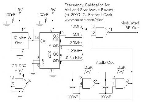
The circuit was built on a hand-wired prototype board as shown in the photo, a more permanent circuit could be built with a OnePas prototype board or a hand-wired perf-board. IC sockets are recommended for more permanent wiring jobs. Selection of the available frequencies can be done with an optional 1P5T rotary switch or a board-mounted 5 position DIP switch. In the prototype shown, frequency selection is done by moving a jumper wire.
The 5VDC supply is provided by an external DC power supply, four 1.25 NiMH cells could also be used. If you use NiMH cells, don't forget to add a fuse and a switch. It is a good idea to build the circuit into a small metal box, use insulated standoffs and machine screws to mount the board to the box.
(View)
View full Circuit Diagram | Comments | Reading(1071)
PC Automatic Power-on Circuit
Published:2013/3/10 22:38:00 Author:Ecco | Keyword: PC Automatic, Power-on Circuit

This project is for a power-on boot sequencer that works with PC-style computers that have a low-voltage controlled power supply such as an ATX or Mini-ITX system. Some computers have built-in BIOS functionality that can be set to boot up the computer when AC power is applied, others do not. This circuit is intended for the latter type of computer.
A desktop PC can be used for a variety of dedicated purposes such as a home automation controller, a burglar alarm or an automatic motion-operated camera. Such a system needs to be able to automatically restart when the AC mains power drops out and comes back on. A battery-backed uninterruptible power supply (UPS) is normally a good solution for this problem, but if the power remains off for long enough, the UPS battery will drain and the computer will eventually power down.
This circuit can be used to manage computers that are located in remote locations. It is also useful for booting normal desktop systems where the power to the CPU, monitor and printer are controlled from a single plug-strip.
This circuit provides the necessary timing to virtually press the PC's power on switch and the PC's reset switch. If the PC uses an external 12V power supply, such as a Mini-ITX device, power for this circuit can come from the PC's power supply. For larger desktop systems, it may be necessary to power this circuit with an external 12V DC supply such as a wall-wart.
(View)
View full Circuit Diagram | Comments | Reading(1420)
Microprocessor RS-232 Reset
Published:2013/3/10 22:36:00 Author:Ecco | Keyword: Microprocessor, Reset
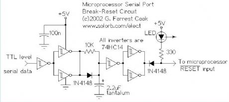
This circuit allows a remote microprocessor to be reset by a controlling host by sending a break signal over an RS-232 or RS-422 serial line. If the remote machine resets into a simple program loader program, it is possible for the host to halt and restart, or halt and reload/restart the remote machine's program. This is an ideal way to develop software on older EPROM-based systems. Modern EEPROM/NVRAM systems use JTAG interfaces for similar results.
The remote processor runs its target code out of RAM, allowing the code to be updated easily. The circuit is usually used for developing code on a target processor, but it can also be used for permanent applications where the target program lives on a host system's disk. This system was once used to load code into a microprocessor-based satellite receiving system in Hawaii from a host system in Colorado using an Internet-based remote serial communications program.
(View)
View full Circuit Diagram | Comments | Reading(764)
Isolated Telephone Interface
Published:2013/3/10 22:27:00 Author:Ecco | Keyword: Isolated Telephone Interface
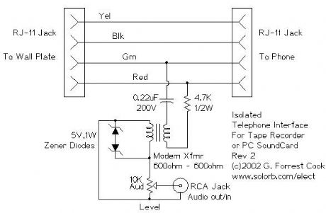
This circuit allows you to record audio from a telephone line into a tape recorder or computer soundcard without any hum. Most of the parts for this circuit can be scrounged from an old modem. With some rewiring work, it should possible to build this project into the old modem's case and re-use the built-in phone connectors.
Note that some countries have laws that require the user of a phone recording device to notify the party on the other end of the line that they are being recorded.
(View)
View full Circuit Diagram | Comments | Reading(1354)
PWM Motor/Light Controller
Published:2013/3/10 22:26:00 Author:Ecco | Keyword: PWM Motor, Light Controller
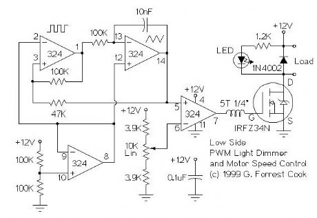
These two schematics are variations on another PWM circuit that I designed. The diagrams are for 12V operation only and there are high side (common ground) and low side (common +12V) versions. The low side version of the circuit uses an N Channel FET, the high side version of the circuit uses a P Channel FET. N Channel devices tend to handle more current than P Channel devices, they are also less expensive. The high side version of the circuit is useful when one side of the load has to be grounded.
This circuit can switch a fairly high amount of current, an IRFZ34N MOSFET can handle over 35 Amps if connected to a proper heat sink. Higher power FETs, such as the IRFZ48N or IRF1010Z can be substituted if even larger currents are required. It is also possible to connect multiple FETs in parallel for even more current capacity. Always use thermally conductive grease between the FET and the heat sink, and remember that the heat sink is electrically live.
Inductive loads (motors) may require special care since they can generate large voltage spikes that can damage the MOSFET. Replacing the 1N4002 with a fast recovery diode may help absorb the reverse voltage kick when driving an inductive load such as a motor. If you use these circuits for experiments with electric vehicles, be sure to install a circuit breaker in series with the battery, the circuit breaker should be easy to reach by the driver. This is especially important due to the fact that when MOSFETs fail, they often short out, leaving the motor on at full speed.
Note that the pwm control has an opposite effect on these two circuits, the low side version is on with a high pin 7 output voltage and the high side version is on with a low output.
The inductor on the gate side of the power MOSFET transistor can be a ferrite bead or a few turns of wire wrapped around a 10 ohm, 1/4W resistor. The purpose of this part is to prevent RF oscillations from occurring in the MOSFET circuitry.
(View)
View full Circuit Diagram | Comments | Reading(1692)
PWM Motor Speed Controller / DC Light Dimmer
Published:2013/3/10 22:25:00 Author:Ecco | Keyword: PWM Motor, Speed Controller , DC Light Dimmer
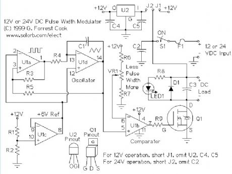
A pulse width modulator (PWM) is a device that may be used as an efficient light dimmer or DC motor speed controller. The circuit described here is for a general purpose device that can control DC devices which draw up to a few amps of current. The circuit may be used in either 12 or 24 Volt systems with only a few minor wiring changes. This device has been used to control the brightness of an automotive tail lamp and as a motor speed control for small DC fans of the type used in computer power supplies.
A PWM circuit works by making a square wave with a variable on-to-off ratio, the average on time may be varied from 0 to 100 percent. In this manner, a variable amount of power is transferred to the load. The main advantage of a PWM circuit over a resistive power controller is the efficiency, at a 50% level, the PWM will use about 50% of full power, almost all of which is transferred to the load, a resistive controller at 50% load power would consume about 71% of full power, 50% of the power goes to the load and the other 21% is wasted heating the series resistor. Load efficiency is almost always a critical factor in solar powered and other alternative energy systems.
One additional advantage of pulse width modulation is that the pulses reach the full supply voltage and will produce more torque in a motor by being able to overcome the internal motor resistances more easily. Finally, in a PWM circuit, common small potentiometers may be used to control a wide variety of loads whereas large and expensive high power variable resistors are needed for resistive controllers.
The main Disadvantages of PWM circuits are the added complexity and the possibility of generating radio frequency interference (RFI). RFI may be minimized by locating the controller near the load, using short leads, and in some cases, using additional filtering on the power supply leads. This circuit has some RFI bypassing and produced minimal interference with an AM radio that was located under a foot away. If additional filtering is needed, a car radio line choke may be placed in series with the DC power input, be sure not to exceed the current rating of the choke. The majority of the RFI will come from the high current path involving the power source, the load, and the switching FET, Q1.
(View)
View full Circuit Diagram | Comments | Reading(4441)
PWM DC Motor Speed Control
Published:2013/3/10 22:23:00 Author:Ecco | Keyword: PWM, DC Motor , Speed Control
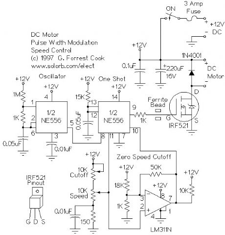
The left half of the 556 dual timer IC is used as a fixed frequency square wave oscillator. The oscillator signal is fed into the right half of the 556 which is configured as a variable pulse width one-shot monostable multivibrator (pulse stretcher). The output of the one-shot is a variable width square wave pulse, the pulse width is set with the speed control pot on the control voltage input. The variable width output pulse switches the IRF521 MOSFET transistor on and off. The MOSFET amplifies the current of this signal so that it is powerful enough to control a small DC motor. The 311 comparator is used to cut off the one-shot via the reset pin when the control voltage is below a certain threshold, the 311 is also controlled by the speed control pot. The cut off circuit is necessary because the 556 one-shot circuit will always put out a small pulse, even when the control voltage is at zero.
(View)
View full Circuit Diagram | Comments | Reading(2716)
Arduino LFO Waveform Generator V1
Published:2013/3/10 22:18:00 Author:Ecco | Keyword: Arduino, LFO Waveform , Generator, V1
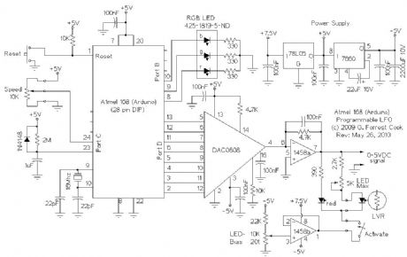
This project uses an Arduino microprocessor and a DAC0808 8 bit parallel DAC to produce arbitrary low frequency oscillator (LFO) waveforms. These waveforms are useful for driving a tremolo/vibrato circuit in a guitar amplifier such as the Lil Tiger or a phaser effect such as the Liquidator. The second version of this project improves on this design by using a serial DAC chip and an analog speed control.
The initial version of this project was build using the Arduino Diecimila development board and an Arduino prototype shield for the DAC and associated parts. The original assembly can be seen in the photographs of the Lil Tiger project. The second generation version (as shown in the schematic) was built using just the Arduino's Atmega 126 processor chip on a stand-alone circuit board. The microprocessor should be programmed on the Arduino board then moved to the standalone LFO board. The circuit is a descendent of my older waveform generator project.
(View)
View full Circuit Diagram | Comments | Reading(7851)
Panner Waveform Generator
Published:2013/3/10 22:16:00 Author:Ecco | Keyword: Panner Waveform Generator
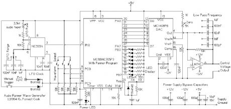
This device is a microprocessor controlled waveform generator that can be used for driving a voltage controlled stereo panner for music applications. Panning is simply the movement of a mono audio signal between the left and right channels of a stereo sound system.
The circuit can also be used to drive other voltage controlled modules that are used in analog music synthesis. The output of the waveform generator is a 0-10V DC control voltage.
One of eight waveforms can be selected using an 8 position BCD switch. Waves include: ramp, triangle, sine, cos(x)*sin(5x), damped 4 cycle sine wave, and pseudo random. Other waveforms may be substituted by changing the assembly language waveform tables.
The waveform generator runs in an asyncronous manner, int can be syncronized with other devices by use of an external (5V logic) sync signal or a manual sync trigger button. The waveform is generator is clocked by an oscillator circuit, the oscillator has three range selections, and an LFO rate control for fine speed adjustments.
The output waveform can be smoothed with an adjustable low pass filter. This can be used to remove the stair steps in the output waveform for a more rounded waveform.
An array of 8 LEDs is included for displaying where the current panning position is located, these are spread evenly across the device front panel for an interesting visual effect.
(View)
View full Circuit Diagram | Comments | Reading(935)
Nine Volt Battery Eliminator
Published:2013/3/10 22:15:00 Author:Ecco | Keyword: Nine Volt, Battery Eliminator
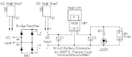
Effect pedals for electric guitars are typically powered by 9 volt batteries. These batteries cost several bucks each and don't often last very long. Leaving a pedal turned on overnight by accident guarantees a dead battery in the morning. Why spend your precious money on a constant supply of batteries when you can build this easy substitute that won't fade away right in the middle of that killer guitar solo. This device is not limited to use in guitar pedals, it can be used with guitar tuners, radios and other small 9V devices. The circuit can be built to support DC or AC wall warts, the AC version requires a bridge rectifier. I've build many of these out of surplus materials, they make good gifts for guitar players.
(View)
View full Circuit Diagram | Comments | Reading(2501)
Vacuum Tube Stereo Microphone Preamp
Published:2013/3/10 22:12:00 Author:Ecco | Keyword: Vacuum Tube, Stereo Microphone, Preamp

This microphone preamplifier is designed to interface a dynamic microphone directly to a computer's sound card input. It can also be used as a mic preamp for analog recorders. The circuit is configured like a mixing board input strip so that each microphone has its own bass and treble cut/boost control. With a larger power supply, this preamp could easily be doubled to provide four channels.
The project was inspired by your author's attempts to record live audio using various small solid-state mixing boards with built-in mic preamps. The preamps all produced high levels of hiss and a quieter mic preamp was desired. The hiss problem is multiplied when making a multi-track audio recording since each new track adds to the combined hiss level.
(View)
View full Circuit Diagram | Comments | Reading(4060)
Low Power 6U8A Vacuum Tube Audio Amp
Published:2013/3/10 22:11:00 Author:Ecco | Keyword: Low Power, Vacuum Tube, Audio Amp
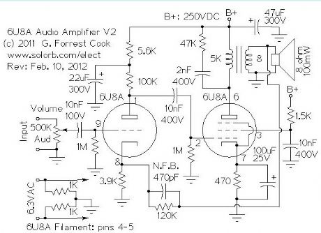
The line-level audio signal is sent through a 100K audio volume control and into the grid of the 6U8A triode section. The triode is wired as a standard class-A tube amplifier. The B+ line to the triode is isolated from the final amplifier's B+ through a 5.5K/22uF low pass filter, this prevents interstage feedback and oscillation.
The output of the triode amp is sent to the control grid of the 6U8A pentode section through a 10nF capacitor. The pentode is wired as a class-A amplifier with a transformer output. A negative feedback loop linearizes the amplifier's frequency response, this consists of a 120K resistor and 470pF capacitor from the speaker side of the output transformer to the cathode of the 6U8A triode. Feedback is kept to a fairly light level to preserve the amp's dynamics. The R/C network across the output transformer primary was adjusted for a flat frequency response. The pentode's screen grid is pulled up to the B+ voltage through a 1.5K current limiting resistor and AC-bypassed with a 10nF capacitor.
If a tone control is desired, it can be built onto the feedback loop, see my Squirrel Monkey amp project for an example of this type of tone control. If you build the amplfier and it oscillates, swap the output leads on the output transformer to correctly phase the feedback signal.
The power supply is not shown, this amp is designed to be an audio module that can be combined with other modules to build a radio or other audio devices. Any standard vacuum tube power supply should work here, it just needs to provide 6.3VAC for the filament and 250VDC for the B+ circuit. The amp should work fine with B+ values between 150VDC and 300VDC. Again, see my Squirrel Monkey amplifier for a power supply that will work with this amplifier.
(View)
View full Circuit Diagram | Comments | Reading(4055)
The Howler Monkey Push Pull 6AQ5 Guitar Amp
Published:2013/3/10 21:57:00 Author:Ecco | Keyword: Howler Monkey , Push Pull , Guitar Amp
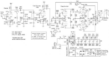
This amplifier is a push-pull design which features a pair of 6AQ5 beam power tubes driven by a 6J6 dual triode, all of which are 7 pin miniature tubes. It is the higher power successor to the the Squirrel Monkey amp project. In fact, the only thing this amp has in common with the Squirrel Monkey amp is the choice of an electrical wiring box for the chassis and a monkey in the name. The 6AQ5 tubes were commonly used as single ended audio output amplifiers in radios and televisions, they are plentiful and inexpensive on the surplus market.
The 6AQ5 output tubes are described in the RCA receiving tube manual as being lower voltage versions of the larger 6V6 beam power pentodes. The maximum undistorted power output from this amplifier is about 5 watts, which is plenty loud for a practice amp. The amp works well driving either a 10 or 12 guitar speaker. A big advantage of the lower power 6AQ5 output tubes is their ability to reach plate starvation, with it's inherently pleasant sounding distortion, at much lower volume levels. This can be an advantage for recording, and for those who wish to preserve their hearing. There are several military versions of the 6AQ5 including the 6005 and the 6094, the latter is a 10K-hour tube with ceramic spacers and thick glass.
The 6J6 dual triode is ideally suited for use as a long-tailed pair phase inverter since the two cathodes are tied together internally. The preamp and tone control recovery amps use a common 12AU7 dual triode, higher gain 12AT7 and 12AX7 tubes can be substituted for the 12AU7 if more gain is desired. The 12AU7 produces a cleaner and softer sound than the higher gain tubes. If one wishes to build the amp entirely with 7 pin tubes, two common 6C4 triodes can be substituted for the 12AU7.
(View)
View full Circuit Diagram | Comments | Reading(5560)
The Squirrel Monkey One Tube Guitar Amp
Published:2013/3/10 21:55:00 Author:Ecco | Keyword: Squirrel Monkey, One Tube , Guitar Amp
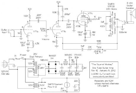
The guitar input jack feeds directly into class-A preamp VT1a, the single high gain triode section in the 6AF11. The preamp output feeds into the volume control pot, and that drives the power amp circuitry, VT1b and VT1c.
VT1b is the first gain stage in the power amp, it includes negative feedback input on the cathode and a high cut R-C network on the plate to lower RF sensitivity. VT1b feeds the output stage, pentode VT1c. Both VT1b and VT1c are running in class-A mode. The pentode is cathode biased to the tube's optimal 24mA by the 160 ohm resistor. The 180K resistor from the transformer output to the VT1b cathode adds a small amount of negative feedback for stabilizing the amplifier. The 3nF capacitor across the output transformer keeps the output stage from oscillating in the RF region.
The tone control is somewhat non-standard, it involves an adjustable high pass network within the power amp's negative feedback loop. The negative feedback inverts this function to make an adjustable high cut filter. The tone control's response is quite useful, musically.
There are a lot of Fender 5E3 fans out there who think that negative feedback is a bad thing in any form. From my experiments, I have found that the secret to using negative feedback is to use a minimal amount. That greatly reduces the production of bad-sounding distortion, while preserving the good-sounding distortion and punchy presence. Bad-sounding distortion is visible on an oscilloscope as very steep waveforms (RF), while good-sounding distortion is visible as the soft rounding of the tops of the waves as a result of plate starvation.
A number of different junk box output transformers were tried in this circuit with minor variations in the performance. A 3.5K to 8 ohm transformer produced the most power output of the transformers that were tested. Since this is a relatively low power amplifier, it is not nececessary for the output transformer to be perfectly matched to the tube, although the volume will be loudest when the match is ideal. Transformers with input impedances from 2.5K to 10K should work and a common 5K to 8 ohm transformer would be a good choice if you cannot locate a 3.5K to 8 ohm unit.
The power supply section uses a standard 6.3VAC/2 Amp filament transformer for lighting the tube filaments up, two 220 ohm resistors cancel out any filament-induced hum.
The high voltage transformer uses a bit of trickery that has been seen elsewhere on Internet amplifier designs. A 28VAC/1 Amp (1/2 Amp would work) transformer with dual primaries is rewired so that one primary winding became a secondary winding and the 28V secondary voltage was added to the 120V secondary to produce 148VAC. This feeds into a bridge rectifier to produce the high voltage DC, which is around 210V with no load. A more common 24VAC dual primary transformer should also work fine here.
The high voltage DC is filtered through a capacitive/inductive pi filter to remove hum and produce the B1+ supply. The B1+ supply runs at around 180VDC with the tube plugged in. The B1+ supply is further filtered through an R/C filter to produce an isolated B2+ supply for the first two gain stages, this runs at around 175V. The 2M resistor discharges the capacitors when power is removed.
(View)
View full Circuit Diagram | Comments | Reading(3487)
| Pages:155/2234 At 20141142143144145146147148149150151152153154155156157158159160Under 20 |
Circuit Categories
power supply circuit
Amplifier Circuit
Basic Circuit
LED and Light Circuit
Sensor Circuit
Signal Processing
Electrical Equipment Circuit
Control Circuit
Remote Control Circuit
A/D-D/A Converter Circuit
Audio Circuit
Measuring and Test Circuit
Communication Circuit
Computer-Related Circuit
555 Circuit
Automotive Circuit
Repairing Circuit