
Circuit Diagram
Index 147
60 / 120 watts Power Amplifier LM4780
Published:2013/3/18 1:51:00 Author:Ecco | Keyword: 60 / 120 watts , Power Amplifier
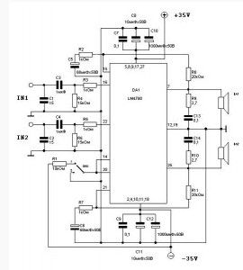
Operating power amplifier integrated circuit LM4780 from National Semiconductor .What is special? Well, first of all – it is very low harmonic distortion. Typically, manufacturers indicate the maximum power of its regular genius crafts at THD 10%. At the same chip, the CG at the maximum specified power is only 0.5%!
(View)
View full Circuit Diagram | Comments | Reading(1756)
25/50 W Power Amplifier Class D based MAX9709 chip
Published:2013/3/18 1:45:00 Author:Ecco | Keyword: 25/50 W , Power Amplifier, Class D
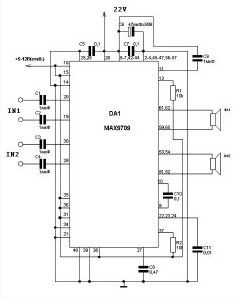
Despite the relatively small power output specified in the title of the article, it has one distinct advantage – the acoustics can be connected directly to pins – no extra coils is not required – as they say – all included.
(View)
View full Circuit Diagram | Comments | Reading(1195)
Microphone Amplifier using KM551UD2
Published:2013/3/18 1:44:00 Author:Ecco | Keyword: Microphone Amplifier
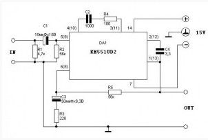
The amplifier is assembled on operational amplifier KM551UD2.The amplifier is powered by a dual supply voltage of 15 volts. The diagram shows one channel of amplification, and is given in parentheses the numbering of the findings for the second channel.
(View)
View full Circuit Diagram | Comments | Reading(1125)
Car Power Amplifier based TDA1562
Published:2013/3/18 1:43:00 Author:Ecco | Keyword: Car Power Amplifier
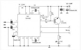
Audio amplifier is built with the main component of Philips TDA1562 IC. The TDA1562 is a monolithic integrated 70 W/4 W.Bridge-Tied Load (BTL) class-H high efficiency power amplifier in a 17 lead DIL-bent-SIL plastic power package. Its essence is that to a certain value output (approx. 20 watts) amplifier operates in the mode B. If the output power increases further, included a clever scheme to increase the voltage output stage and thus enables the amplifier to swing to a maximum power of 70 watts.
(View)
View full Circuit Diagram | Comments | Reading(2036)
A Simple 20 Watts Amplifier
Published:2013/3/18 1:40:00 Author:Ecco | Keyword: 20 Watts, Amplifier
The scheme is very simple and if you decide to devote himself to the assembly of amplifiers and investigation of their activities, it makes sense to start with this amp.
(View)
View full Circuit Diagram | Comments | Reading(2061)
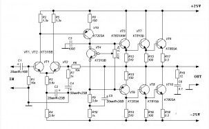
100 Watt High Quality Power Amplifier
Published:2013/3/18 1:39:00 Author:Ecco | Keyword: 100 Watt, High Quality, Power Amplifier
The amplifier is completely based on discrete elements without any OS and other tricks. When working on the load and power 4 Ohm 35V amplifier has an output up to 100W. If there is a need to connect the load 8 Ohm power can be increased to + /-42V, in this case, we get the same 100W.
It is strongly recommended not to increase the voltage more than 42V, or you can go without the output transistors. When operating in bridge mode to be used an 8-ohm load, or, again, are deprived of any hope for the survival of the output transistors. By the way, we must note that the protection against short-circuit in the load is not provided, so you have to be careful. To use the amplifier in bridged mode, you must login MT bolted to the output of another amplifier to the input signal and which. The remaining input is closed to ground. Resistor R11 is used to set the quiescent current output transistors. Capacitor C4 determines the correct boundary gain and reduce its not worth it – get the self-oscillation at high frequencies.
(View)
View full Circuit Diagram | Comments | Reading(5065)
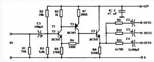
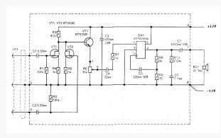
Microphone Amplifier with Noise Suppression
Published:2013/3/18 1:38:00 Author:Ecco | Keyword: Microphone Amplifier , Noise Suppression
The following microphone amplifier, in addition to its primary mission, will suppress common mode noise arising in the wire connecting the microphone and amplifier.
The circuit is divided into two parts. Left – is located in close proximity to the microphone, for example, in his case. The right-hand – anywhere – in the amplifier, a mixer. Connect these two pieces of two-wire, shielded cable.
How does it work? It’s very simple – a signal from a microphone, amplified the left side is fed to the right side, the input stage of which (VT3, VT4) is an accumulator with a phase shift of 180 degrees (the phase of the signal, not of what you think.) Thus, the useful signal coming out of phase two wire folded and its value is doubled. And the nasty in-phase noise are mutually self-destruct.
(View)
View full Circuit Diagram | Comments | Reading(1734)
Simple High Quality Tube Amplifier Class A
Published:2013/3/18 1:29:00 Author:Ecco | Keyword: Simple High Quality, Tube Amplifier, Class A

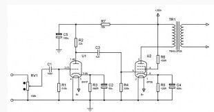
Amplifier built on a wide spread basis element, and the values of elements may differ from those listed at 10-20 percent, without degrading the amplifier characteristics.
U1 – 6N1P (one half – the right channel, the other – left); U2 – 6P3S.resistors, used in the amplifier type MLT-0.5, R5 – MLT-2.Capacitors C1, C3, preferably paper – to voltage is less than 300 V.
(View)
View full Circuit Diagram | Comments | Reading(2159)
Single Channel Headphone Amplifier
Published:2013/3/18 1:25:00 Author:Ecco | Keyword: Single Channel, Headphone Amplifier
Headphone amplifier circuit was built by IC DA1 – KR1436UN1 (DIP8). This IC operated on a wide range of voltage between +2V-16V. With small current required, it can be powered by batteries. THD – 0.5%. Freq Frequency 20-20000Hz. Limiting long-term power output – 250mW 16 Ohm load and voltage 6V.
(View)
View full Circuit Diagram | Comments | Reading(1171)
Dual Channel Headphone Amplifier
Published:2013/3/18 1:23:00 Author:Ecco | Keyword: Dual Channel , Headphone Amplifier
Here is a the circuit dual-channel headphone amplifier. The circuit is built with ic DA1 – KR1054UN1, KF1054UN1, AN7050, TDA7050T (SO8 all), TDA7050 (DIP8), which is more expensive than the previous the circuit single-channel headphone amplifier. All devices operate at supply voltage range 1.6-6V. Current, as well as in the single-channel headphone amplifier was not great. THD – 0.1%. Frequency 20-20000Hz. Limiting long-term power output at 32 ohms.
(View)
View full Circuit Diagram | Comments | Reading(1369)
Microphone Amplifier based K548UN1
Published:2013/3/18 1:13:00 Author:Ecco | Keyword: Microphone Amplifier
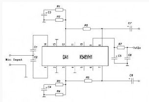
The operating principle is as follows:Resistors R1, R3 is used to adjust the gain, which equals 25. To increase the gain by 75 to build a resistance of 68 ohms. It is not recommended to install too high gain, because it may affect the sound quality, although this depends on the microphone. Capacitors C5 and C6 are used for suppression of feeding.
This circuit has been tried on three microphones, one from SONY, and then two Chinese, everything works! With the correct assembly of the device starts to work immediately, and does not need tuning.
(View)
View full Circuit Diagram | Comments | Reading(1085)
Simple Microphone Pre-amp
Published:2013/3/18 1:11:00 Author:Ecco | Keyword: Microphone Pre-amp
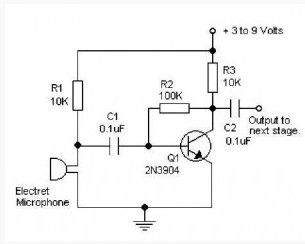
This Simple preamplifier circuit provides sufficient gain to weak audio signals from the microphone. This circuit can also be supplied from the voltage baterry 3 to 9 volts if necessary. Take a note that the microphone used in this pre-amp circuit is electret type.If you are using high fidelity sound system, the this mic pre-amp will not become a good choice, you should be find other circuits.
(View)
View full Circuit Diagram | Comments | Reading(3477)
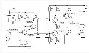
Single Chip Audio Preamplifier LM358
Published:2013/3/18 1:10:00 Author:Ecco | Keyword: Single Chip, Audio Preamplifier
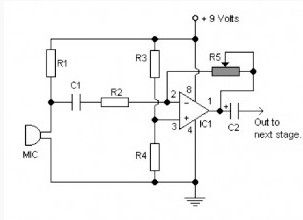
The circuit is based on low power ic LM358 dual op amp with a single 9 volt power supply. This pre amp has a gain which can be set via the variable resistor R5.
(View)
View full Circuit Diagram | Comments | Reading(4690)
Simple Audio Booster
Published:2013/3/18 1:09:00 Author:Ecco | Keyword: Audio Booster
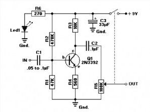
This Audio booster circuit is very simple and can be applied to fm tuner or audio pre amplifier. The 2N3392 is a low-noise type transistor in TO-92 case. The transistor can can be replaced by a NTE199 or ECG199. If you wish to use a TUN, cross reference the parameters with one of the units from this list : TUP-TUN
Potentiometer R5 of 100K is a linear type with an on/off switch attached. The value of C1 may need to be between 0.05µF and 0.1µF (47nF/100nF). Experiment with the value for best performance.
(View)
View full Circuit Diagram | Comments | Reading(1433)
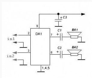
2x22W Car Audio Amplifier Circuit
Published:2013/3/18 1:08:00 Author:Ecco | Keyword: 2x22W, Car, Audio Amplifier
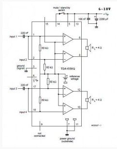
Above is a schematic diagram of an amplifier which is used in car audio. This circuit uses IC TDA 1558 from Philips. TDA1558 is a monolithic integrated class-B Output power amplifier in 17-lead single-in-line (SIL) plastic package. The device contains 4 x 11 W single-ended or 2 x 22 W BTL amplifiers.
(View)
View full Circuit Diagram | Comments | Reading(1898)
Linear Video Amplifier SECAM, PAL and NTSC
Published:2013/3/18 1:07:00 Author:Ecco | Keyword: Linear , Video Amplifier, SECAM, PAL , NTSC
Buffered video amplifier is used wherever the use of video player to the receiver / monitor TV with a long cable may cause a drop in signal amplitude and as a consequence, the deterioration in image quality. The amplifier can also be used to connect multiple receivers to one player or VCR.
In any case, it prevents deterioration of picture quality as eating out edstvie greater load the player, or loss of signal power in the cable. This is a simple linear amplifier with low noise level with a broad band transfer (min 20 MHz) and increased ~ 6 dB. You can connect to any source of stabilized voltage 12-15 (in special cases even from the power supply VCR). Current consumption of a small, 20 mA at 12 V.
The scheme works only when using the compounds of “AV” where video and audio signals are sent separately. Not suitable for joints «HF» antenna cable. Make sure to include the video amplifier in the line of the video, while leaving the audio connection. It is possible to use two amplifiers, one of which will be designed for the line “video” other “audio.”
(View)
View full Circuit Diagram | Comments | Reading(1384)
Headphone Amplifier SONY CXA1622P
Published:2013/3/18 1:06:00 Author:Ecco | Keyword: Headphone Amplifier, SONY

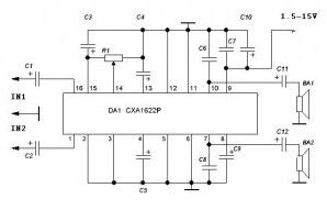
This circuit may be a bit expensive because it uses ic CXA 1622P from SONY. The CXA1622P is a bipolar IC developed as a power amplifier for radio compact cassettes with built-in pre-amplifier and power amplifier electrical volume.
Chip operates at supply voltage range 1.8-6V. THD – 0.7%. Frequency – 40-40000Hz. Resistor R1 is used to adjust the volume.
(View)
View full Circuit Diagram | Comments | Reading(1464)
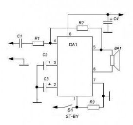
Subwoofer Amplifier for Computer
Published:2013/3/18 1:05:00 Author:Ecco | Keyword: Subwoofer Amplifier, Computer
An integral part of modern multimedia computer is the presence of two active audio speakers (mounted on a monitor or set next to it). Due to a number of physical limitations of the two small computer speakers can not achieve a good reproduction of the full range of sound frequencies. Especially collapses and distorted bass. Therefore, to obtain high-quality background music is usually used yet a third column – the subwoofer.
In high quality active speakers, such as company Altec Lansing, a built-in audio amplifier has an output labeled “SUB” (model ACS40, Fig. 5.1). It is designed to connect low-frequency active column.
This circuit uses IC K174UN14 from Russia. Its gain depends on the ratio of resistors R8-R9. Chain of elements R10-C6 band of amplified frequencies limits that increases the stability of work, excluding the occurrence of generation at frequencies above 100 kHz. Signals from the output of “SUB” come to the mixer, collected from field-effect transistors (VT1, VT2). Provides isolation between the mixer outputs and amplifies the signal by about 3 times. Resistor R6 sets the desired level of sound in the low column BA1 with respect to the lateral columns, and the main (overall) volume control and tone control is usually performed in the main amplifier on the body in a side column or from the program.
(View)
View full Circuit Diagram | Comments | Reading(1816)
Inexpensive 20 Watts Power Amplifier
Published:2013/3/18 1:04:00 Author:Ecco | Keyword: Inexpensive, 20 Watts, Power Amplifier
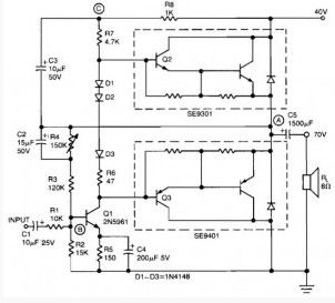
This simple inexpensive 20 watts power amplifier can be constructed using monolitic DArlington transistors for pushpull output stage. Response frequency of this amplifier is flat within 1 dB from 30Hz to 200kHz, harmonic distortion below 0.2%.
For max output Power 20W 8 ohm load amplifier requires only 1.2Vrms. To provide voltage gain for driving the Darlington output, low noise high gain Q1 (2N5961) is needed.Q1 base on (point B) is the tie point for dc and ac feed backas well as the input signal. Input resistence is 10 kohm. The center voltage A is set by adjusting resistor R4. A bootstrap circuit boosts the collector supply voltage of Q1 (point C) to ensure sufficient drive voltage for Q2. This also provides constant volatage across R7, which acts as a current source and with D1-D3 reduces low signal crossover distortion.
(View)
View full Circuit Diagram | Comments | Reading(2124)
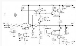
High Power Audio Amplifier 1500 Watt
Published:2013/3/18 1:03:00 Author:Ecco | Keyword: High Power, Audio Amplifier, 1500 Watt
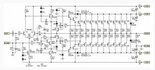
This Powerfull audio amplifier can provide a 2kW power peaks, and 1.5kW continuously, which means that the amplifier can burn your most famous speakers. To provide this power in action you can connect (What do I highly do not recommend), two series-connected 8-ohm speaker in AC 220. In this case the dynamics will be on the same 110V current voltage into 8 ohms – 1,500 W. What do you think will last a long time whether in this mode acoustics.
Transformer 2 x 90V will give no-load voltage ± 130V (260V between the outermost points of the rectifier), so that the power supply to operate with extreme caution.
(View)
View full Circuit Diagram | Comments | Reading(2872)
| Pages:147/2234 At 20141142143144145146147148149150151152153154155156157158159160Under 20 |
Circuit Categories
power supply circuit
Amplifier Circuit
Basic Circuit
LED and Light Circuit
Sensor Circuit
Signal Processing
Electrical Equipment Circuit
Control Circuit
Remote Control Circuit
A/D-D/A Converter Circuit
Audio Circuit
Measuring and Test Circuit
Communication Circuit
Computer-Related Circuit
555 Circuit
Automotive Circuit
Repairing Circuit