
Circuit Diagram
Index 151
The bistable multivibrator circuit diagram
Published:2013/3/14 1:52:00 Author:Ecco | Keyword: Bistable multivibrator
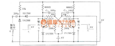
Bistable multivibrator circuit diagram is shown as figure.
(View)
View full Circuit Diagram | Comments | Reading(1100)
Bidirectional monostable circuit
Published:2013/3/14 1:40:00 Author:Ecco | Keyword: Bidirectional monostable

Bidirectional monostable circuit is shown as figure.
(View)
View full Circuit Diagram | Comments | Reading(709)
100kHz self-excited multivibrator
Published:2013/3/7 2:38:00 Author:Ecco | Keyword: 100kHz , self-excited multivibrator
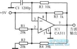
100kHz self-excited multivibrator is shown as figure.
(View)
View full Circuit Diagram | Comments | Reading(924)
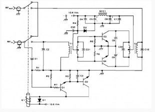
100W PEP 420-450Mhz PUSH-PULL LINIER AMPLIFIER
Published:2013/3/13 2:16:00 Author:Ecco | Keyword: 100W , 420-450Mhz, PUSH-PULL LINIER AMPLIFIER
This is 100 watt linear amplifier and may be built using two MRF309 transistors in push-pull, requiring only 16 watts drive from 420 to 450 MHz.
The 100 watt linear amplifier operating from a 28 volt supply, 8 dB of power gain is achieved along with excellent practical performance featuring: maximum input SWR of 2:1, harmonic suppression more than-63 dB below 100 watts output, efficiency greater than 40%, circuit stability with a 3:1 collector mismatch at all phase angles.
(View)
View full Circuit Diagram | Comments | Reading(1148)
140W ( PEP ) Amateur Radio Linier Amplifier (2 -30 Mhz)
Published:2013/3/13 2:15:00 Author:Ecco | Keyword: 140W , Amateur Radio, Linier Amplifier, 2 -30 Mhz
This amateur radio amplifier circuit this inexpensive and easy to build. This circuit uses two MRF454 NPN transistors. Specified at 80 W power output-with 5 W of input drive, 30 MHz, and 12.5 Vdc.
(View)
View full Circuit Diagram | Comments | Reading(1462)
40W / 2 ohm (24W / 4 ohms) Bridge Power Amplifier (Cheaper Version)
Published:2013/3/13 2:13:00 Author:Ecco | Keyword: 40W , 2 ohm, 24W , 4 ohms, Bridge Power Amplifier
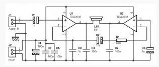
It is possible to simplify the assembly to have a cheaper version of 40W / 2 ohm (24W / 4 ohms) bridge power amplifier, as shown in the above diagram. Small refinements that ensure the reliability in the previous assembly had disappeared, but that does not mean that this simplified installation will not work correctly.
(View)
View full Circuit Diagram | Comments | Reading(1394)
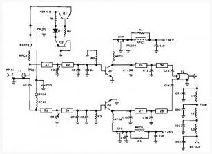
160 W (PEP) Broadband Linier Amplifier
Published:2013/3/13 2:12:00 Author:Ecco | Keyword: 160 W, PEP, Broadband Linier Amplifier
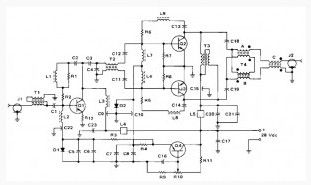
Thisisanothercircuit RF amplifierthat I tookfrom theEncyclopedia ofelectroniccircuitVolumeI. The circuit is quite hard to build since the components is complex and need more attention for the Inductors,
(View)
View full Circuit Diagram | Comments | Reading(1077)
Mono Preamplifier based on TL062
Published:2013/3/13 2:11:00 Author:Ecco | Keyword: Mono Preamplifier
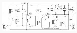
This circuit is perfect pre-amp to amplify the signal from a mono microphone. It is based on the use of a type integrated circuit TL062, a little less known perhaps as the TL082 or TL072 often used by maniacs audio.
This integrated circuit has two operational amplifier in a housing 8-pin, and has good performance alone, mostly in terms of noise and power consumption. Its use for portable audio applications.
(View)
View full Circuit Diagram | Comments | Reading(2144)
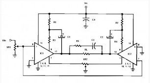
Mono Preamp Based on NE5534
Published:2013/3/13 2:10:00 Author:Ecco | Keyword: Mono Preamp
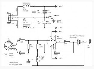
This achievement shows that it is possible to create a balanced dynamic microphone preamp, it is relatively simple. This preamp is particularly suitable for microphones with an output impedance of 200 ohms to 600 ohms. The advantage of the preamplifier is 50 dB, and bandwidth (-3 dB) extends to about 25 KHz. The splitted power supply is required.
The power supply should be treated. It is recommended to use a symmetrical power supply + /-15V using a voltage regulator has less noise, such as the LM317 and LM337.
(View)
View full Circuit Diagram | Comments | Reading(4734)
Preamp for Speaker as a Microphone
Published:2013/3/13 2:09:00 Author:Ecco | Keyword: Preamp , Speaker, Microphone
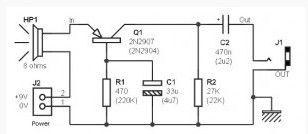

This Microphone Preamp circuit shows that it is possible to use the speaker as a microphone, and is specifically designed to beginners because of its simplicity. Power consumption, of about 2mA, allowing the circuit is operated a few hours on a single 9V battery. However, it does not prevent you to use a stable power supply, or solar cells …
Sources : This setting is described by J. England Smith, the magazine ETI in January 1979. It is also found in an old French electronic magazine, the same scheme but with different component values.
(View)
View full Circuit Diagram | Comments | Reading(1415)
Preamp for Speakers as a Microphone 2
Published:2013/3/13 2:07:00 Author:Ecco | Keyword: Preamp , Speakers , Microphone
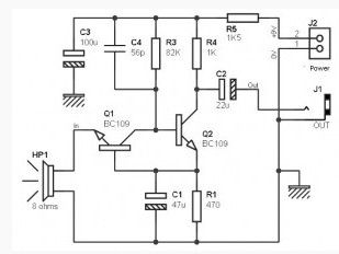
The previousPreamp for the speakers as a microphone installationis indeedsimple,buthasvirtuallyno gain.It isquite possibleto add asecond transistorto fill the gap, as shown in above diagram.Note thatthe resistor R1serves asthe polarizationof the two transistorsQ1 and Q2.At the same time, the transistorinput matchinghas becomeanNPN.
(View)
View full Circuit Diagram | Comments | Reading(1732)
Small Electret Microphone Pre-amplifier
Published:2013/3/13 2:06:00 Author:Ecco | Keyword: Small Electret, Microphone , Pre-amplifier

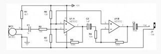
The mic pre amp described here is designed to connect a small electret microphone and uses an integrated circuit type NE5532.
As you can see, this scheme is very simple. The use of a dual operational amplifier type NE5532 is a large part in simplicity, although it was quite possible to simplify even more by using a single transistor.
(View)
View full Circuit Diagram | Comments | Reading(2980)
Low Voltage Bridge Audio Amplifier
Published:2013/3/13 2:05:00 Author:Ecco | Keyword: Low Voltage, Bridge Audio Amplifier
Low voltage bridge audio amplifier based on op amp IC LM386 (Low Voltage Audio Power Amplifier). Application of this circuit include AM-FM radio amplifiers, Portable tape player amplifiers, intercoms, TV sound systems, Line drivers Ultrasonic drivers, Small servo drivers Power converters. This circuit can be operated by battery power.
This Low voltage bridge audio amplifier circuit is for low voltage applications requiring high power outputs. Output power levels of 1.0 W into 4 ohm from 6 V-and 3.5 W into 8 ohm from 12 V are typical. Coupling capacitors are not necessary since the output dc levels will-be within a few tenths of a volt of each other. Where critical matching is required the 500 K potentiometer is added and adjusted for zero dc current flow through the load.
(View)
View full Circuit Diagram | Comments | Reading(2047)
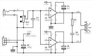
Non-Inverting Amplifier Using Split Supply
Published:2013/3/13 2:04:00 Author:Ecco | Keyword: Non-Inverting Amplifier, Split Supply
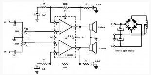
Non-inverting amplifier uses a dual audio power amplifier LM1877 type. This IC can deliver output power of 2 W per channel.
As the title that this circuit requires a dual power supply circuit as shown in the schematic above. This Non-inverting audio amplifier circuit may be applied to Multi-channel audio systems, stereo phonographs, tape recorders and players, AM-FM radio receivers, servo amplifiers, Intercom systems, Automotive products.
(View)
View full Circuit Diagram | Comments | Reading(1068)
Mono/Stereo Preamp based on LM387
Published:2013/3/13 2:03:00 Author:Ecco | Keyword: Mono/Stereo Preamp
Mono Preamp (or stereo), based on an LM387 for dynamic microphone. The preamplifier described here is designed to connect a small dynamic mic. We will see that it can adapt to a wide range of microphones.
As you can see, Mono Preamp (or stereo), based on an LM387 diagram is very simple. It is based on the use of an LM387, which is really common, but has proven in the field of “low noise”, just like its cousin the LM381.
(View)
View full Circuit Diagram | Comments | Reading(2010)
Mono Preamp based on CMOS IC CD4069
Published:2013/3/13 2:02:00 Author:Ecco | Keyword: Mono Preamp , CMOS IC
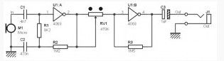
Microphone preamp described here is not a professional preamp, but the original preamp and it is cheap and easy to build. Why the original? Because it does not use non-conventional transistors or operational amplifiers (op amps) to amplify the signal from the microphone, but a set of logic gates are commonly used in digital electronics. Digital ICs used are as in the title above which is cmos CD 4049.
As said above, this scheme there are no transistors or components “analog” to ensure amplification of the signal from the microphone. Except for only two logic gates share the work. Microphones, which are provided to capture the sound,connected to the input of the first logic gate U1: A. This ensures that the amplifier logic gate rate is determined by the value of the resistors R1 and R2. The second logic gate U1: B, in turn, ensures that amplification can be adjusted using potentiometer RV1.
(View)
View full Circuit Diagram | Comments | Reading(1790)
Mono Preamp with Small Transformer and Two Transistors
Published:2013/3/13 2:01:00 Author:Ecco | Keyword: Mono Preamp , Small Transformer , Two Transistors
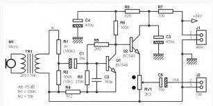
The microphone preamplifier described here is a ‘hybrid’ passive / active. A small transformer input provides a small contribution to the gain of all (about 10 dB), and a transistor provides the additional gain (35 dB) for normal use with a small dynamic microphone. About 40 kHz bandwidth, small and simple installation that requires little space.
(View)
View full Circuit Diagram | Comments | Reading(1390)
5W / 8 Ohms Bridge Amplifier based on Two LM380s
Published:2013/3/13 1:28:00 Author:Ecco | Keyword: 5W , 8 Ohms, Bridge Amplifier
The Audio amplifier described here uses two small amplifiers like LM380 mounted in bridge. Two smallamplifiersLM380(2.5Wmaxineach18V), which mountedbridgemode make it possible togetafew wattsinto 8ohms load.
LM380 mounted on the first non-inverting amplifier, the audio signal connected to + input. The second inverting amplifier mounted on the same audio signal line and connected at the input -. Input (inverting input of U1 and U2 non-inverting input) is not connected to anything. In fact, the internal resistance of 150 Kohm C1 reduces this input to ground. Both amplifiers each have a gain of 34 dB (voltage gain of about 50), the value specified by the manufacturer LM380. With 12 V power supply voltage and input power around 100mV can be generated around 4 W. Power of 5 W is achieved with a supply voltage of 18 V (even with this voltage can reach 6 W without any problems).
(View)
View full Circuit Diagram | Comments | Reading(2027)
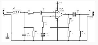
Max 1W / 8 Ohms Amplifier based on LM386 with Input for Guitar
Published:2013/3/13 1:26:00 Author:Ecco | Keyword: Max, 1W , 8 Ohms, Amplifier , Input , Guitar
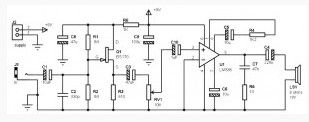
This 1 watt amp is very easy to built in very small dimensions, working with only single 9V battery, and is based on amplifier IC type LM386, its capable to deliver a power for some hundreds milliwatts to 8 ohms load, while consuming only a few mA at rest.
Associated with a small FET input stage, this amplifier is ideal for beginners to make some small electric guitar amplifier. Don’t think you will get results similar to those offered by the amps of a certain class, but for someone who starts in the DIY, and choosing a good size of speaker driver, it’s a nice little montage.
(View)
View full Circuit Diagram | Comments | Reading(1572)
Simple Amplifier Circuit 3W / 8 ohm
Published:2013/3/13 1:25:00 Author:Ecco | Keyword: Simple Amplifier , 3W , 8 ohm
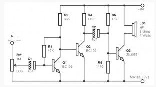
These Simple amplifier based transistor 3W / 8 ohm are very small and very easy to carry, work with single supply between 4V and 9V. It is based on the use of common transistors and is able to provide some low wattage.
(View)
View full Circuit Diagram | Comments | Reading(3328)
| Pages:151/2234 At 20141142143144145146147148149150151152153154155156157158159160Under 20 |
Circuit Categories
power supply circuit
Amplifier Circuit
Basic Circuit
LED and Light Circuit
Sensor Circuit
Signal Processing
Electrical Equipment Circuit
Control Circuit
Remote Control Circuit
A/D-D/A Converter Circuit
Audio Circuit
Measuring and Test Circuit
Communication Circuit
Computer-Related Circuit
555 Circuit
Automotive Circuit
Repairing Circuit