
Circuit Diagram
Index 154
100W bridge amplifier based TDA7294
Published:2013/3/12 1:10:00 Author:Ecco | Keyword: 100W , bridge amplifier
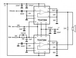
This 100W bridge amplifier circuit can increase the power level of the audio signal from a source that has a LINE output type.
(View)
View full Circuit Diagram | Comments | Reading(4440)
20W stereo amplifier based LM1876
Published:2013/3/12 1:09:00 Author:Ecco | Keyword: 20W , stereo amplifier
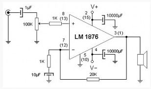
This two-channel amplifier provides power to 20 watts RMS from two line inputs. Ideal for use in computers since its price / performance / complexity is optimal.
In the 20 watt stereo amplifier circuit observed only one stage of the system because the circuit stereo, second channel are identical. The figures in parentheses are equivalent to the terminal for second channel. The core of this project is the integrated circuits from National Semiconductor, the LM1876, which provides two power operational amplifier with mute and standby function.
(View)
View full Circuit Diagram | Comments | Reading(2511)
Multidirectional microphone amplifier
Published:2013/3/12 0:57:00 Author:Ecco | Keyword: Multidirectional microphone , amplifier

This Multidirectional microphone amplifier circuit is often used in a panel discussion or a meeting room to capture the audio from all the partners without the need to give each microphone. Placing this in the middle of the table captures audio from each through which is formed by four electret capsules with a level control for each individual reception.
We can say that this Multidirectional microphone circuit consists one side of electret four modules, each of them provide power to the capsule through 10K resistor, DC blocked through 1μF capacitor and the resulting AF signal is received at the end of the potentiometer which serves as a reception setting. 100K resistors and transistors form a network FET preamp and summing several signals, which can be applied without any problems on the line input as the microphone channel of the console.
(View)
View full Circuit Diagram | Comments | Reading(1562)
10 W Audio Amplifier based TDA 2003
Published:2013/3/12 0:55:00 Author:Ecco | Keyword: 10 W, Audio Amplifier
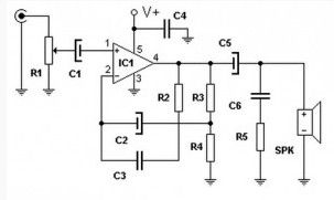
With only one active integrated circuit TDA 2003 as component this circuit can provide up to 10W of audio power to the load which can be between 2 and 8 ohm.
(View)
View full Circuit Diagram | Comments | Reading(2090)
High quality 10W Audio Amplifier
Published:2013/3/12 0:54:00 Author:Ecco | Keyword: High quality, 10W , Audio Amplifier
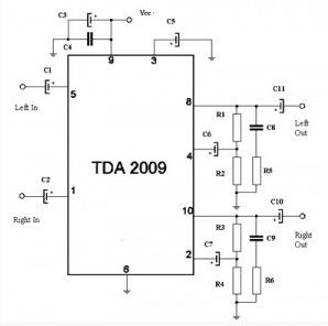
The main components of this high quality 10W stereo power amplifier circuit is uses TDA 2009 which is a class AB Audio Power Amplifier. IC TDA 2009 is specifically designed for high quality stereo applications such as HI-FI and music center.
As you can see on the circuit, this class AB amplifier IC requires only a few external components. And this 10 W audio amplifier circuit is also very easy to build. This 10W stereo amplifier circuit requires a stable power supply with a voltage of 18 V and 1A current needs.
(View)
View full Circuit Diagram | Comments | Reading(1998)
100 W valve audio amplifier
Published:2013/3/12 0:53:00 Author:Ecco | Keyword: 100 W , valve, audio amplifier
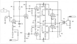
This is a valve audio amplifier circuit which can provide power up to 100W.
(View)
View full Circuit Diagram | Comments | Reading(1965)
80W power amplifier circuit with TDA7294
Published:2013/3/12 0:51:00 Author:Ecco | Keyword: 80W , power amplifier
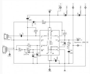
Power Amplifier based tda7294 from ST microeletronics, you can gain power up to 100W in a single chip, for stereo unit, use similar two circuits. This circuit is based on the manufacturer’s datasheet for tda7294 typical application usage. Amplifier is ready to work with a powerful signal source, if necessary, use an opamp pre-amplifier.
This type of 80w power amplifier circuit chip is ideal for surround sound systems. Since this is quite compact and can be used for independent amplifier for each speaker. In this way it can be upgraded to share source to support all of the connected amplifier.
(View)
View full Circuit Diagram | Comments | Reading(2173)
Audio Power amplifier (30W)
Published:2013/3/11 21:03:00 Author:Ecco | Keyword: Audio Power amplifier , 30W
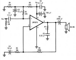
The following circuit uses LM1875 audio amplifier capable of delivering up to 30W RMS power into 8 ohm speakers with a total harmonic distortion (THD) 1%.
(View)
View full Circuit Diagram | Comments | Reading(2259)
12W FET audio amplifier
Published:2013/3/11 21:02:00 Author:Ecco | Keyword: 12W , FET, audio amplifier
This is a small 12W power amplifier on a load of 8 Ω, that combining the NE5534 integrated technology with transistors as V-MOSFET output stage get an excellent sound quality. The input sensitivity is 3V rms maximum, the distortion factor is 0.002% at 1 kHz, and frequency response is 15 Hz to 100 kHz. (-3dB).
(View)
View full Circuit Diagram | Comments | Reading(3388)
75W Transistor Audio Amplifier
Published:2013/3/11 21:00:00 Author:Ecco | Keyword: 75W , Transistor, Audio Amplifier
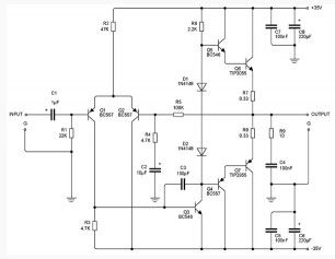
It is simple to build an amplifier, using the standard and stable and reliable. The 75 W amplifier circuit presented here is capable of driving 4 ohm, but, although used in 4 ohms, this amplifier has very few errors.
To be aware that there are no short-circuit output, so that when the speaker short, while the amplifier is working (with signal), there is a very real danger that may damage the transistor.
(View)
View full Circuit Diagram | Comments | Reading(5998)
100 W audio amplifier based LM12CLK
Published:2013/3/11 20:59:00 Author:Ecco | Keyword: 100 W , audio amplifier
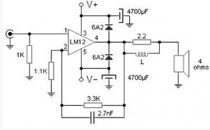
The 100W audio power amplifier is powered by the integrated circuit LM12CLK which is operational power amplifier. The monolithic IC can deliver 80W of sine wave power into 4Ω load with 0.01% distortion. Power bandwidth is 60 kHz .. Important features of IC LM12CLK include : controlled turn on, overvoltage shutdown, output-current limiting, dynamic safe-area protection, thermal limit, Input protection
This amplifier allows to operate at 2 Ω output impedance and gain 150W of power. For savety and system stability, this 100W audio amplifier is designed to work with 4-Ω speaker to gain the power of the 100W RMS.
(View)
View full Circuit Diagram | Comments | Reading(1953)
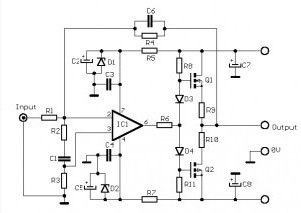
12W amplifier circuit based 741 Op Amp
Published:2013/3/11 20:57:00 Author:Ecco | Keyword: 12W amplifier , Op Amp
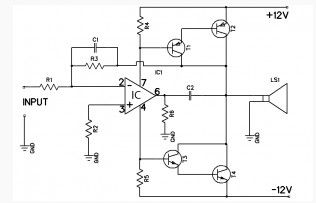
This Amplifier is 12 watts and to operate this is use source of dual symmetric ± 12 volt. The 741 provides the required gain while the speaker unit driven by complementary Darlingtons T1, T2 and T3, T4.
Input signal to the Darlington comes from the feed current 741. Since R6 is connected to earth, positive or negative current signal is also going through R4 or R5. The voltage drop across this resistance serves as the input signal to the transistor pairs. A common dc negative feedback from the collector junction with T2 and T4 stabilize the DC circuit and the junction point is maintained at zero volts. So, there is no coupling capacitor needed for the speaker.
(View)
View full Circuit Diagram | Comments | Reading(1862)
2 watts amplifier schematic diagram
Published:2013/3/11 20:54:00 Author:Ecco | Keyword: 2 watts, amplifier
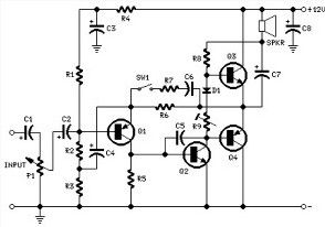
The amplifier is designed for independent in a small speaker box. Can support to Walkman, Mini-Disc and CD players, computers, and similar devices with line or headphone output. Of course, in many cases, you will need to create two units for stereo.
(View)
View full Circuit Diagram | Comments | Reading(1375)
The PC Serial Port Receiver circuit
Published:2013/3/10 23:08:00 Author:Ecco | Keyword: PC Serial Port , Receiver
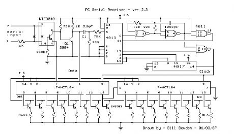
This circuit requires physical connections be made to the computer's serial port (COM1 or 2). To the best of my knowledge, it is difficult to cause damage to yourself or your computer by improper connections to this port, but there is no guarantee that damage will not result. Use caution when making any external electrical connections.
(View)
View full Circuit Diagram | Comments | Reading(1977)
Constant Temperature Circuit
Published:2013/3/10 23:05:00 Author:Ecco | Keyword: Constant Temperature

The 7805 voltage regulator provides a reference voltage that is fed into a resistive bridge formed on one side by the 20K trimmer and the other side by the 3.3K resistor and the 1K/thermistor combination. The termistor is an NTC (Negative Temperature Coefficient) type. The op-amp is run in a differential mode and tries to keep its inputs at the same potential by the thermal feedback loop formed by the heater and the thermistor.
The three 1N4001 diodes are used to bias the emitter of the transistor up enough that it can shut off fully with the limited voltage swing from the 741 op-amp. The heating indicator LED (a standard red LED) also taps off of the same diode ladder to enable it to shut off entirely.
The value of the (1uF) capacitor in the op-amp feedback loop may need to be adjusted if the circuit rings , or swings back and forth before stabilizing on a temperature. The capacitor value is specific to the thermal mass that is being temperature stabilized.
The heater resistor is rated at approximately 40 ohms and 5 watts. The value of the resistor determines the heating rate and the power consumption. The resistor value should not be too low or the resulting high current will damage the 1N4001 diodes and/or the TIP122 transistor.
(View)
View full Circuit Diagram | Comments | Reading(1692)
Lightning Activated Camera Shutter Trigger
Published:2013/3/10 23:03:00 Author:Ecco | Keyword: Lightning Activated Camera, Shutter Trigger
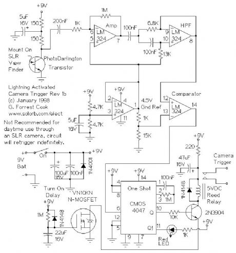
In a nutshell, the photo darlington converts light pulses into electrical pulses, the first LM324 section amplifies the electrical pulses, the second LM324 section is a high pass filter that only passes quick changes (lightning). The third LM324 stage is a comparator that allows only large pulses to pass through, and the 4047 one-shot stretches out the length of the pulses so that they are long enough to drive the relay and trigger the camera.
The 2N3904 drives the reed relay, which in turn triggers the camera's electronic shutter switch. The VN10KM prevents the circuit from triggering the camera when it is first turned on. The LM324 GND Ref circuit divides the 9V power into two for a 4.5V ground reference. The other op-amp circuits use this reference value.
(View)
View full Circuit Diagram | Comments | Reading(1153)
Temperature Controlled NICD Charger
Published:2013/3/10 23:02:00 Author:Ecco | Keyword: Temperature Controlled, NICD Charger
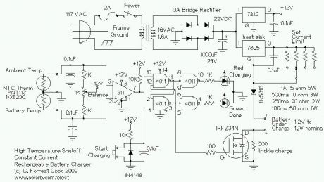
This circuit is for a temperature controlled constant current battery charger. It works with NICD, NIMH, and other rechargeable cells. The circuit works on the principle that most rechargeable batteries show an increase in temperature when the cells becomes fully charged. Overcharging is one of the main causes of short cell life, hot cells pop their internal seals and vent out electrolyte. As cells dry out, they lose capacity. This circuit can quickly charge a rechargeable battery pack without any negative effects. This circuit uses a 22VDC power supply, my version 2 circuit can run from a 12VDC supply such as a solar-powered or automobile power system.
(View)
View full Circuit Diagram | Comments | Reading(1738)
Ultra Low Power LCD Indicator
Published:2013/3/10 22:59:00 Author:Ecco | Keyword: Ultra Low Power, LCD Indicator
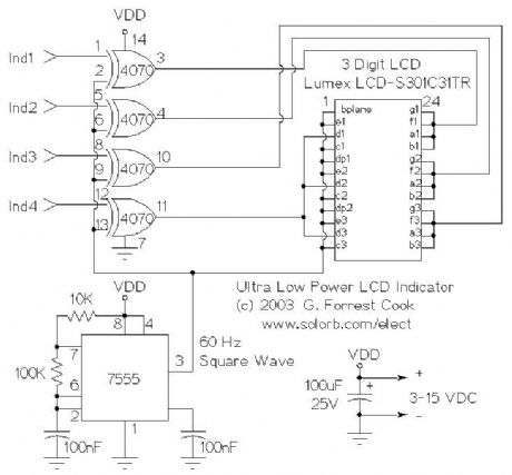
The 7555 IC (CMOS 555 timer) generates a square wave clock signal at approximately 60 hz. This signal is sent to the LCD backplane and the inputs of the four CMOS 4070 XOR gates. If the other input (ind*) of an XOR gate is low, the gate's output is a square wave that is in phase with the clock signal. If the ind* input is high, the gate's output is out of phase with the clock.
Sending a signal to an LCD segment that is in phase with the backplane signal causes the display to stay blank. Sending an out of phase signal to the LCD segment causes an AC waveform to be applied to the segment which turns it black. Multiple segments are wired in parallel to generate the desired display patterns. The LCD segments require a tiny amount of current to operate, the CMOS gates also take very little power, hence the efficient nature of the circuit. It is necessary to tie the unused segments to the LCD backplane, otherwise they may partially turn on.
If more dislay bits are needed, additional XOR gates can be connected in the same manner. Up to 23 XOR gates could be used to drive the entire display, but a microprocessor and driver software would probably be easier to put together. By generating all of the signals with a microprocessor, all of the driving circuitry can be eliminated.
Other logic families could be used to make this circuit, it should work with a standard 555 timer chip and a 74LS86 XOR gate (different pinout), for example.
Some LCDs may not operate at very cold temperatures, an engineer at Lumex said that their components will work from -30C to +75C.
(View)
View full Circuit Diagram | Comments | Reading(1664)
The Big-E Stereo Parabolic Microphone
Published:2013/3/10 22:58:00 Author:Ecco | Keyword: Big-E , Stereo, Parabolic Microphone
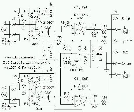
The circuit consists of two identical audio channels and some basic power supply filtering components. Only the left channel will be described.
The mini condenser microphone converts sounds into an electrical signal. Resistor R1 provides bias for the condensor microphone's internal amplifier transistor. The 2N3906 PNP transistor acts as a low noise microphone input amplifier. The 10K gain potentiometer is used for adjusting the audio signal level. A stereo 10K audio taper pot can be used for adjusting both channels simultaneously, or individual 10K trimmers can be used for fixed gain applications. The preamp output signal is fed into the 1458 op-amp, which boosts the audio to a level that is sufficient for driving an 8-ohm headphone or a tape recorder input. The 1458 amplifier stage is fixed gain (10X) in the inverting configuration, it drives the headphone speakers.
Capacitor C9 provides DC isolation from the 1458 op-amp output, which sits at half of the supply voltage. Resistor R13 provides impedance protection for the op-amp output and reduces audio distortion when driving low impedance headphones.
DC bias for the 1458 op-amps is set at half of the supply voltage by the R16/R17 voltage divider. Capacitors C13 and C14 filter the DC power supply for the op-amp stage. The DC is further filtered for the input preamp transistors through resistor R15 and capacitor C11. Diode D1 and resistor R18 protect the circuit from reverse battery polarity.
(View)
View full Circuit Diagram | Comments | Reading(1757)
Motorized Video Camera Mount
Published:2013/3/10 22:53:00 Author:Ecco | Keyword: Motorized, Video Camera , Mount
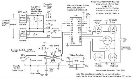
The camera rotator circuit uses a 2716 EPROM to store a table of logic values that control the motor driver (H-bridge) circuit. The EPROM data is shown in the schematic. By using the EPROM, a large number of discrete gates are eliminated. The logic table is designed to allow the motor to turn clockwise until the clockwise limit sensor is activated. The same operation happens with counter clockwise rotation and the counter clockwise limit sensor.
Four bits of input come from the limit sensors and the direction control switch, these go to the EPROM address lines. All of the input signals are low-active. Four EPROM outputs go to the four H-bridge transistor gates. The control switch signals are buffered through the 7400 quad NAND gate, this allows for a long control wire. The control wire should be a shielded type such as beldfoil and the shield should be grounded at only one side.
The H-bridge array consists of two N-channel MOSFETs and two P-channel MOSFETs. Diagonal pairs of transistors are turned on to move the motor one way or the other. If all of the transistors are off, the motor does not move. Note that the P channel transistors turn on with a 0 logic output level and the N channel transistors turn on with a 1 logic output level.
There are several disallowed output states, if the wrong two transistors are turned on, the transistors and voltage regulator would heat up and possibly be destroyed. Don't do this. If the EPROM is programmed correctly, this should never happen.
(View)
View full Circuit Diagram | Comments | Reading(2342)
| Pages:154/2234 At 20141142143144145146147148149150151152153154155156157158159160Under 20 |
Circuit Categories
power supply circuit
Amplifier Circuit
Basic Circuit
LED and Light Circuit
Sensor Circuit
Signal Processing
Electrical Equipment Circuit
Control Circuit
Remote Control Circuit
A/D-D/A Converter Circuit
Audio Circuit
Measuring and Test Circuit
Communication Circuit
Computer-Related Circuit
555 Circuit
Automotive Circuit
Repairing Circuit