
Circuit Diagram
Index 156
Spartacus Hammond AO-44 Organ to Guitar Amp Conversion
Published:2013/3/10 21:54:00 Author:Ecco | Keyword: Spartacus , Hammond Organ , Guitar Amp Conversion
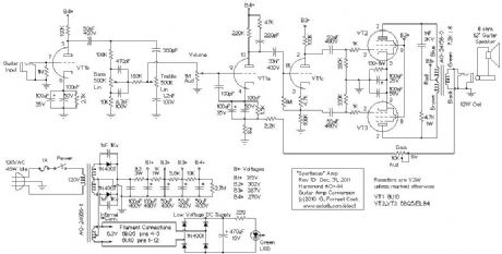
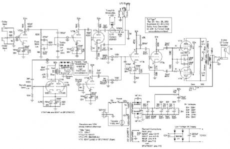
This amplifier is a variation on the Hammond AO-44 Reverb Amp to Hi-Fi Amp Conversion project. The goal is slightly different: the Spartacus amp has more gain and higher output power, making it better for use as a guitar amplifier. Unlike the previous project, the Spartacus amp involves a complete rewire of the Hammond AO-44 chassis. The hard to find 6GW8/ECL86 tubes are replaced with more common and higher power 6BQ5/EL84 tubes. Output power is around 12 Watts, that may not seem like much, but the amp can get quite loud. A cool looking 6U10 compactron triple triode is added to the amp's chassis, it provides the first two gain stages and the phase inverter stage.
The name Spartacus was inspired by the ancient slave who broke free from the Romans and wreaked havoc for many years. Like its namesake, the amp makes an excellent stereo guitar slave amp when used in conjuction with projects such as the Hammonator 2RVT and Lil' Tiger amps. The Spartacus amp can also break free and function as an independent amp, it works nicely with a 12 guitar speaker.
The Hammond AO-44 amplifier chassis can be found on eBay for reasonable prices. The Spartacus design is simple and clean. The wiring is dense, but not overly difficult to assemble. The controls include the basic volume, bass and treble adjustments as well as a gain control. The gain (negative feedback) control is more than just a second volume control, it adjusts the the character of amplifier's sound from compressed and tight to open and loud like the popular Fender 5E3 amp.
(View)
View full Circuit Diagram | Comments | Reading(2936)
Fuzzy Firebottle Guitar Distortion Pedal
Published:2013/3/10 21:52:00 Author:Ecco | Keyword: Fuzzy Firebottle, Guitar Distortion Pedal
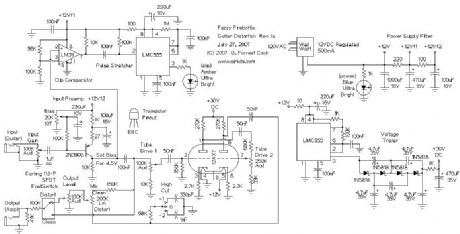
Power is supplied to the device from a 12VDC wall-wart transformer supply. Be sure that the wall-wart really produces 12VDC, many of these devices only produce their rated voltage at a given load current. A LM7812 voltage regulator (with a heat sink) may be used between a 14-18VDC unregulated supply and the distortion circuit. The +12VDC supply is initially filtered with a 1000uF capacitor, it is further filtered to the +12Vf1 and +12Vf2 supplies through two more R/C lowpass sections.
The +30VDC tube plate supply voltage is produced by an LMC555 CMOS timer chip set to generate square waves. The square waves are fed to a voltage tripler circuit which produces around 30VDC. The tripler uses 1N5818 Schottky diodes instead of regular silicon diodes to produce the full 30V. The +30V supply is filtered through the 1K and 470uF RC lowpass filter before being sent to the 12AX7 plate circuits (B+). The tube filament supply is provided directly from the +12VDC supply line.
The guitar audio signal is fed to the 2N3906 amplifier stage via a 100K input gain potentiometer. The 2N3906 bias is set to a fixed (class A) level by the 20K trimmer potentiometer. The 27 ohm emitter resistor provides negative feedback to limit the maximum gain for the 2N3906 amplifier stage. The output of the 2N3906 amplifier produces the clean signal for the mixer and the input drive to the first of the 12AX7 triode sections.
The clean signal is sent to the LM311 + input in the clipping circuit. The LM311 - input is set to a fixed 6.9VDC level. When the 2N3906 emitter signal goes above 6.9VDC with large input signals, the LM311 output signal switches from low to high. This is fed through the 100nF capacitor to the input of the LMC555 pulse stretcher circuit (one shot). On the return from high to low, the pulse stretcher triggers and the the amber LED blinks on for a few tens of milliseconds to indicate clipping.
The clean audio signal is sent to the grid of the first 12AX7 section through the 100K drive control. If the drive control is set high, the signal on the first 12AX7 plate is distorted. The plate signal from the first 12AX7 section is fed to the second drive control via a 50nF DC blocking capacitor. The signal on the second 12AX7 plate is even more distorted. The distorted signal from the second 12AX7 plate is sent through a 50nF DC blocking capacitor and fed to the Mix control.
The High Cut switch optionally puts a 68K/330pF or 68K/1nF RC filter to reduce the high frequency harmonics. The center tap of the Mix control contains a mix of the clean and distorted signals. This is sent to the Output Level control and switched to the Output jack via the foot switch and through the 100K/47K attenuator.
(View)
View full Circuit Diagram | Comments | Reading(1651)
FuzzniKator Push-Pull Tube Distortion/Preamp Box
Published:2013/3/10 21:51:00 Author:Ecco | Keyword: FuzzniKator, Push-Pull Tube , Distortion, Preamp Box

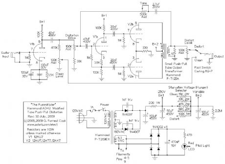
There are zillions of guitar distortion circuits on the Internet, many with funny names. The FuzzniKator is somewhat unique among the lot. The circuit was inspired by the great distortion sound that tube amps give a guitar during the seconds after the power has been shut off and the signal is fading out. The effect is also similar to a cranked tube amp driving a resistive speaker attenuator. The circuit uses a special starved push-pull tube output stage driving an output transformer which drives a resistive load. The push-pull output tubes are run from an adjustable (and lower than normal) B+ voltage in order to starve the tubes and produce distortion. The push-pull configuration and transformer output produce a more harmonically pleasant distortion compared to most diode-clipped distortion effects.
The starvation voltage and drive signal are adjustable for a wide variety of sounds. The FuzzniKator also has a clean tube preamp channel that is similar to a classic Fender amp's tube front-end circuit. The clean channel works nicely as a tube preamp stage and the distortion channel makes any amp, solid state or tube, sound warm and fuzzy.
(View)
View full Circuit Diagram | Comments | Reading(2923)
Liquidator Tube Phaser/Chorus Effect
Published:2013/3/10 21:50:00 Author:Ecco | Keyword: Liquidator Tube, Phaser, Chorus Effect
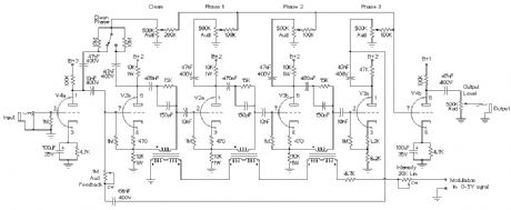
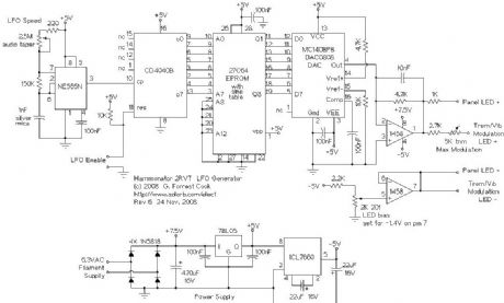
This project involves the conversion of a Hammond AO-47 organ vibrato unit (Original Hammond Schematic) into a 4 phase guitar/music phaser/chorus box. The individual phase signals can be mixed for a wide variety of sounds. The Liquidator name comes from the liquidy sounds that the device creates, it wiggles the audio all around. Used Hammond vibrato units can often be purchased for little money on eBay and provide the majority of the circuitry for this device. The Hammond AO-41 box can also be used for this project, it has one extra 7 pin tube socket. The Liquidator's companion project is the FuzzniKator Tube Distortion/Preamp.
Builders should have decent technician and metalworking skills to build this project. A chassis and power supply with input output jacks, power line, knobs and switches needs to be constructed. The AO-47 box needs many soldering modification to convert it to the phaser/chorus circuit. Additionally, an LFO circuit needs to be constructed from an Arduino microprocessor platform to make the appropriate control waveforms. Thanks to the tube circuitry, the audio quality of this phaser is superior to a transistor or op-amp based phaser, the level of hiss is very low.
(View)
View full Circuit Diagram | Comments | Reading(3459)
Lil Tiger Hammond AO-43 Organ to Guitar Amp Conversion
Published:2013/3/10 21:48:00 Author:Ecco | Keyword: Lil Tiger, Hammond Organ , Guitar , Amp Conversion
This project follows in the footsteps of the Hammonator and Hammonator 2RVT organ amplifier to guitar amplifier conversion projects. A variety of Hammond tube amps are available on eBay for reasonable prices and they make a good platform for a guitar amplifier project. The Hammond AO-43 chassis is a prime candidate for conversion, it is large enough to build a full-featured amp with reverb and other effects and has a bare side that can hold many knobs and jacks.
This amp has undergone a number of design changes since the original version was published. A second copy of the amp was constructed and the reverb driver tube was changed from a 6SN7 to a more period-correct 6FQ7/6CG7. The reverb driver circuitry was changed to include a Reverb Send control, this gives the amp a much wider variety of reverb sounds. The volume and reverb return controls have been wired in a mixer configuration which is somewhat unusual for amp designs. This makes it possible to listen to the reverb channel by itself or to have a mix with very heavy reverb. The vibrato circuit was also rebiased to produce a more intense effect. I liked the rev 2 modifications enough that I applied them to the original amp.
The output stage of this amplifier uses 6BQ5/EL34 pentodes wired in a cathode-biased push-pull configuration, audio power output is around 15W. In the Hammonator project, almost all of the original circuitry was replaced. In this amp, most of the original power amp circuitry was reused. It is important to replace all of the electrolytic capacitors with new parts or bridge new capacitors across the old ones since the original capacitors have probably dried up and become lower in value. All of the resistors should be checked to verify the correct value, old resistors that are run hot tend to go up in value and should be replaced.
The vibrato is somewhat subtle when the amp is played by itself. To get the best vibrato effect, a second amplifier should be plugged into Guitar Input 2 to tap into the input signal. The resulting stereo signal moves around the room in a manner that sounds a lot like a rotating Leslie speaker. Beware, once you get used to playing through a stereo setup all other amps will sound flat.
One could consider this to be a left-handed amp, the signal path and knobs are mostly right to left. The chassis tube layout made this necessary.
(View)
View full Circuit Diagram | Comments | Reading(4369)
Hammonator 2RVT Organ to Guitar Amp Conversion
Published:2013/3/10 21:46:00 Author:Ecco | Keyword: Hammonator, Organ , Guitar, Amp Conversion
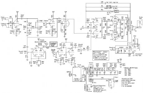
This project is a feature-added version of the Hammonator 1 Hammond organ to guitar amplifier conversion project. The Hammonator 1 circuit worked as a basic guitar amplifier, this version adds some very nice sounding vacuum tube audio effects. The 2RVT model number means: 2nd Generation, Reverb, Vibrato and Tremolo. Two copies of the Hammonator 2RVT amp have been made (see photos), both have been working nicely for years. The design has stood the test of time.
The reverb uses a classic sounding tube circuit with a class A triode driving an 18 reverb pan. The reverb has both dwell (input) and output level controls. A pitch-shifting vibrato / volume shifting tremolo circuit is part of the signal path. The vibrato produces a variety of interesting phase shift sounds, from slow movement to warbling.
Stereo vibrato can be easily achieved by chaining a second clean cannel amp's input to the Hammonator's second input jack, or by driving the amp from the Side Channel Output connection. Stereo greatly enhances the vibrato effect, the sound appears to move around the room. A cheap guitar practice amp makes an ok secondary amp, a tube amp such as the Spartacus or the Howler Monkey will produce an even better sound. The Tremolo/vibrato switch changes the pitch shifting vibrato effect into a volume shifting tremolo effect. The wide range of LFO speeds produce some interesting tremolo effects.
(View)
View full Circuit Diagram | Comments | Reading(1054)
Hammonator Organ to Guitar Amp Conversion
Published:2013/3/10 21:44:00 Author:Ecco | Keyword: Hammonator Organ, Guitar Amp Conversion
In the world of electronics, vacuum tubes are almost obsolete. Nearly the last holdout, the cathode ray tube (CRT), is rapidly being replaced by the LCD and other new technologies. Despite this trend, the vacuum tube has seen a big revival in the field of guitar amplifiers, and to a lesser extent, hi-fi amplifiers. Vacuum tubes and related parts have become more readily available in recent years as numerous companies have tapped into this market.
The reason for the popularity of tubes in guitar amps involves the nice tones that are produced when tubes are driven to the point of distortion. For some background on this, follow some of the links on The Strat Monger. There are numerous solid state modeling amps that try to simulate vacuum tube amps with digital signal processing (DSP) techniques, but in the end, that method is never more than a simulation. It just ain't the same as the real thing.
One can spend a large amount of money and time building a tube amp from scratch. Hammond organ ampifiers chassis are available on the surplus market for a reasonable price, they make a good starting point for a guitar amp. The difficult job of cutting chassis holes for the tubes and transformers is already done, one just needs to drill a few holes for the potentiometers and connectors. This project started with the amplifier from a Hammond M2 organ, chassis model AO14-1B.
The output stage of this amplifier resembles a fusion between a Fender Princeton Reverb, Fender Vibroverb and ham radio transmitter. With 6V6 output tubes running at a 420V plate voltage, it puts out approximately 18 watts of audio power. The 17 reverb tank provides a deep echoey sound. The simpler is better philosophy was used in the design, multiple inputs with their own preamp stages were intentionally avoided to reduce hiss. The amp is plenty loud, and the sound quality is excellent. The Hammonator amp has worked well driving both 12 and 15 guitar speakers.
(View)
View full Circuit Diagram | Comments | Reading(2305)
Hammond AO-44 Reverb Amp to Hi-Fi Amp Conversion
Published:2013/3/10 21:43:00 Author:Ecco | Keyword: Hammond , Reverb Amp , Hi-Fi Amp Conversion
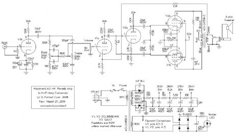
The Hammond AO-44 reverb amplifier was designed to be used an a secondary reverb channel amp in Hammond A-100 and M-series organs. These units can easily be converted into a mono tube amplifier that is suitable for use as one channel in a stereo amp, aka a Mono Block amp. The audio power output is around 8 watts. This project makes a good introduction to working with tubes.
The AO-44 chassis can also be turned into a higher power guitar amplifier using a pair of 6BQ5 pentodes and a 6U10 compactron, see the Spartacus Amp project for details. The Spartacus project is more involved, it requires replacing most of the AO-44 circuitry. The AO-44 amps are currently available for reasonable prices on eBay.
(View)
View full Circuit Diagram | Comments | Reading(3193)
Stereo Test Tone Generator
Published:2013/3/10 21:42:00 Author:Ecco | Keyword: Stereo Test, Tone Generator
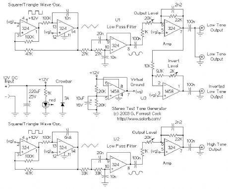
This circuit produces two audio frequency sine waves with different frequencies but equal amplitudes. It can be used for testing a variety of stereo audio equipment. The circuit was originally developed the purpose of aligning an FM Stereo Modulator, like the type used in low power FM stereo transmitters. Two tone outputs are available, the low tone has a secondary output that is 180 degrees out of phase with the primary output. The circuit is also handy for testing computer sound card inputs. A variety of waveform configurations can be produced by plugging a stereo audio patch cord into the four output jacks.
(View)
View full Circuit Diagram | Comments | Reading(1353)
Stereo Audio Isolator
Published:2013/3/10 21:40:00 Author:Ecco | Keyword: Stereo Audio Isolator
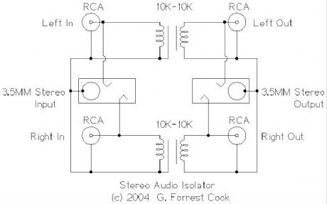
This circuit is useful for removing ground loop hum on a remote line level audio signal line. It can be used to to connect a computer sound card to a stereo amplifier's line input. Other uses include tapping into a line level signal for powering a remote amplifier, and removing common mode ground interference on 12 Volt audio equipment such as a car stereo. The circuit can be used in mono applications by simply ignoring the second channel.
(View)
View full Circuit Diagram | Comments | Reading(1556)
The House Finch Direct Conversion Tube Receiver
Published:2013/3/7 3:14:00 Author:Ecco | Keyword: House Finch, Direct Conversion Tube , Receiver

After building the Little Chickadee 6U8A vacuum tube 80 meter CW transmitter project, your author decided that it would be a good idea to build a companion 80 meter tube CW receiver. A direct-conversion design seemed like a good approach since it is fairly simple and is effective for receiving morse code. Not wanting to reinvent the wheel, the Internet was searched for vacuum tube direct conversion designs. Surprisingly, no other projects were found. The online projects that were found were either solid state designs or regenerative tube circuits.
Nature abhors a vacuum, but not necessarily a vacuum tube so this project was born. Of course, designing something new with vacuum tubes is not an entirely rational pursuit. Rationalizations aside, tube projects are fun, nostalgic and they glow in the dark. This project was a lot more difficult to complete than originally anticipated, but solving the many problems was certainly educational. Those who copy this design should have a much easier time getting the circuit running. It should be farily straightforward to adapt this design to other HF ham bands by changing the resonant sections in the front end filter and oscillator.
The 6U8A audio amp project was already functioning nicely and was perfect for the audio amplifier stage in a communications receiver. The 6U8A seemed like a good choice for the mixer and oscillator circuits. In fact, that's how the 6U8A is usually used. One can think of the 6U8A as a vacuum tube equivalent (sort of) of the popular NE602 IC. The first version of this receiver used just two 6U8A tubes, it worked (barely), but there was a need for additional audio gain and isolation between the antenna and the mixer. The 6C4 preamp tube and the 6BA6 RF amplifier tubes were added to solve these problems.
The receiver is divided into three physical sections, 1: the RF filter and amplifier, 2: the mixer, oscillator and audio filters and 3: the audio amplifier. A few extra grid bias resistors and filament hum cancelation resistors were added so that the individual sections can be disconnected and operated in a stand-alone mode. This also allows the sections to be used as stand-alone modules for other projects. An external power supply provides 6.3VAC for the filaments and 250VDC for the B+ supply, the supply can be shared between this receiver and the companion Little Chickadee transmitter.
(View)
View full Circuit Diagram | Comments | Reading(3399)
The Little Chickadee 6U8A QRP Transmitter
Published:2013/3/7 3:11:00 Author:Ecco | Keyword: Little Chickadee , QRP Transmitter
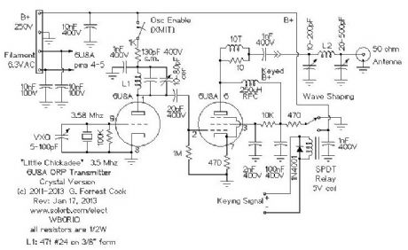
The triode section of the 6U8A is used as a tuned crystal oscillator stage in the crystal version of the circuit and a tuned amplifier in the VFO version. The triode's tuned circuit consists of L1, a fixed-value silver mica capacitor and a ceramic compressions trimmer capacitor. For 80 meter operation, the silver mica capacitor should be 130pf and for 40 meter operation, the capacitor should be 22pF. L1 is made with 47 turns of #24 insulated wire on a 3/8 air core cardboard form, this works for both 40 and 80 meters. The trimmer capacitor should be adjusted so that the circuit resonates at the crystal frequency. Resonance can be observed with an oscilloscope, the probe should be lightly coupled to the oscillator plate, connect the scope probe to the plate via a small capacitor such as 5pF.
The crystal version of this transmitter is rock bound to a particular frequency. Common 3.58 Mhz crystals can be used, but this frequency tends to be occupied by digital-mode signals. It is a good idea to use the crystal oscillator (VXO) variable capacitor to shift the frequency up a few kilohertz to a quiet spot on the band. Other frequencies can be used by switching different crystals into the circuit or using a crystal socket. The oscillator's tank circuit should be re-peaked for different crystals if they are more than a few tens of kiloherz apart in frequency.
(View)
View full Circuit Diagram | Comments | Reading(2078)
All-Ears QSK Timing Generator
Published:2013/3/7 3:10:00 Author:Ecco | Keyword: All-Ears, QSK, Timing Generator

In the world of amateur (ham) radio morse code communications, QSK refers to a method of operation where the transmitter and receiver are alternately active when the key is down or up. QSK is also known as break-in keying. QSK operation allows the operator to hear what is happening on their frequency in the brief times between transmitting morse code dits and dahs. The conversation can be quickly interrupted by the other station, or by a third station. The sender also knows immediately if their signal is being interfered with.
The design of a QSK-capable radio station is somewhat tricky. A QSK system has to quickly switch the antenna between the transmitter and receiver, key the transmitter, mute the receiver during transmission and disable the transmitter's oscillator during receiving. It is also desirable to change the receiver's AGC response time from fast to slow when not transmitting. By adding small delays at the beginning and ending of the dots and dashes, it is possible to generate signals with slightly longer and shorter lengths compared the original morse code. These modified signals sequence the entire system in order to eliminate transmitted chirps, T/R relay arcing and receiver clicking.
Here's a typical sequence for sending one morse code dit , items in parentheses happen simultaneously: (key down, T/R relay to transmit, transmitter oscillator on, receiver mute), delay, transmitter output on for duration of dit, (key up, transmitter output off), delay, (T/R relay to receive, transmitter oscillator off, receiver unmute) Additionally, the receiver AGC slow/fast signal needs to go to fast at the beginning the the first key down event, and should switch to fast a few seconds after the last key up event.
This circuit takes a TTL-level keying signal and produces three TTL-level output signals, and inverted versions of the three signals. This combination of outputs is useful for driving a variety of control circuits that can interface to the transmitter and receiver. The timing generator also generates the necessary signals for automatic non-QSK transmit/receive switching.
(View)
View full Circuit Diagram | Comments | Reading(1827)
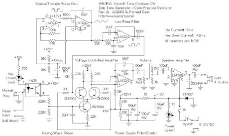
Smooth Tone Clickless CW Sidetone Generator
Published:2013/3/7 3:08:00 Author:Ecco | Keyword: Smooth Tone, Clickless, CW Sidetone Generator
This circuit is essentially a minimal version of an analog music synthesizer that is hard-wired for the purpose of making morse code tones.
The oscillator section produces a fixed frequency triangle wave on LM324 pin 14, that is fed into a low pass filter to get a sine wave on LM324 pin 8. A triangle wave can be thought of as a series of sine waves with decreasing amplitudes as the frequency increases. The low pass filter simply removes the upper harmonics and passes the fundamental sine wave frequency through.
The sine wave is sent to a voltage controlled amplifier made from three 2N3904 transistors. The upper two 2N3904 transistors should be a matched-gain pair in order to minimize thumping sounds. The VCA is modulated with a keying waveform to produce the resulting modulated waveform. The keying waveform is generated by smoothing out the square wave keyed signal on the 4N32 emitter with the 220K/220K/20n (.02uF) capacitor/resistor low pass filter on the base of the lower transistor. The two 220K resistors in series with the 4N35 output transistor act as a voltage divider, this causes the the keying envelope to swing between 0V and 6V, which is a good range for controlling the VCA.
Keying of the circuit is performed either by the manual key input, or via the keyer input, which can be used to connect the circut to a morse code keying chip. To use the keying input, an active low open collector driver should be used.
The audio signal comes out of LM324 pin 7, it connects to a 10K volume potentiometer and an attenuator made with two resistors. The attenuated audio is then fed to the LM386 audio amplifier.
(View)
View full Circuit Diagram | Comments | Reading(2315)
Morse Code Beacon Keyer
Published:2013/3/7 3:07:00 Author:Ecco | Keyword: Morse Code , Beacon Keyer

This circuit stores a morse code message as bits in an EPROM chip, the message is sent to a relay which can key a CW transmitter. The keyer can output either a one-shot message such as CQ DX DE CALLSIGN , or a continuous message. The continuous mode is useful for making beacons for low power (QRP) and slow (QRSS) transmissions. A One-shot message can be controlled by pressing the start/stop buttons, a continuous message can be sent by turning on the free run switch.
EPROMs other than the 2732 can be used if suitable changes are made to the address lines in the circuit. For larger EPROMs, just ground the higher order address input lines on the EPROM chip, and wire the appropriate chip select pins for outputs enabled and chip selected.
It is also possible to store more than one message in different banks of a larger EPROM, for instance, if a 2764 part were used, the A12 address line could be used to select the upper or lower message.
Note that the photo above shows a slightly different implementation of the circuit. A 5V power supply and a 555 timer sidetone oscillator have been added, the keyer relay has been removed and the EPROM is a 2716 type.
(View)
View full Circuit Diagram | Comments | Reading(1704)
LED Mood Light
Published:2013/3/7 3:05:00 Author:Ecco | Keyword: LED Mood Light

TheoryThe current flows and the LEDs light. There are 4 series strings of LEDs in this circuit, the resistors limit the current through the LEDs and prevent them from burning up. The resistors were adjusted to get approximately 20ma through each string. Different LED colors will have different voltage drops and resulting current flows. These resistor values will work fine at 12V.
Construction
The circuit was mounted in a plastic 35MM photographic slide box with a translucent plastic top (not shown). A piece of perforated board was cut to fit inside of the slide box, the LEDs and resistors were inserted through the holes in the board and the wires were soldered together on the back side of the board. It is recommended that you use a heat sink on the LED leads while you solder them, it is very easy to damage an LED with a soldering iron. A length of speaker wire was used to connect the lamp to the power source. The circuit board was connected to the plastic box with one 6-32 screw and several 6-32 nuts were used as spacers.
(View)
View full Circuit Diagram | Comments | Reading(1320)
13 Color LED Rainbow
Published:2013/3/7 3:04:00 Author:Ecco | Keyword: 13 Color, LED Rainbow
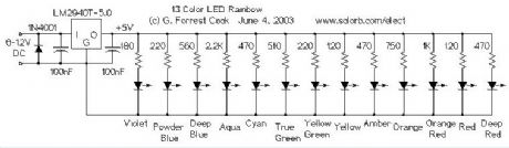
The LM2940T-5.0 low dropout voltage regulator converts the 6-12V DC input power to regulated 5 Volts. It was chosen over a standard 7805 regulator so that the circuit could maintain regulation while operating on a 6V battery. The 1N4001 diode protects the circuit from reverse polarity, if a battery or power supply capable of generating over 1 amp is used, a 1 amp fuse should be installed between the supply and the circuit. The 5 Volts is used to drive each of the LEDs through individual current limiting resistors. The resistor values were determined experimentally for equal brightness. Values are given as examples only, different sources of LEDs will require different resistor values. Resistor selection turns out to be the most difficult part of the circuit's construction. A 100 ohm resistor in series with a 1K pot could be used in place of each resistor if individual brightness adjustments are desired. The table below lists the LED colors and wavelengths.
(View)
View full Circuit Diagram | Comments | Reading(2457)
Remote Solar LED light
Published:2013/3/7 3:03:00 Author:Ecco | Keyword: Remote, Solar LED light
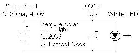
The remote solar powered LED light takes advantage of the current limited nature of solar photovoltaic cells. If light shines on the solar array, current will flow through the circuit. For a typical size of solar cell, there is a maximum current that can be produced. The maximum solar cell current is simply matched to a value of current that the LED can handle. If there is enough light to raise the solar panel's voltage above around 3.7V, the white LED will light up. The LED regulates the maximum voltage across the circuit to around 3.7V.
If the solar panel that you use produces more than 20ma, it may be necessary to insert a series resistor between the LED and the solar panel to prevent the LED from burning out. A 50 ohm 1/4 watt resistor is probably about right for the job, the exact value may need to be optimized according to the solar panel that you use.
This concept could easily be expanded to systems with larger arrays of solar cells and more LEDs. The capacitor is not required, but it will keep the LED from flickering if the panel is briefly blocked, such as when a bird flies by. With 7 solar cells, the LED will only light in fairly bright light, if you use up to 10 solar cells, the circuit will work nicely in overcast skies.
For an interesting modification to this circuit, replace the 1000uF capacitor with a 1 Farad/5.5V Memory Backup Capacitor . An Elna DB-545D105 device was tested on the circuit, after charging up in the sun for a few minutes, the capacitor was able to light the LED for several minutes.
(View)
View full Circuit Diagram | Comments | Reading(1111)
Solar Charged LED Utility Light
Published:2013/3/7 3:02:00 Author:Ecco | Keyword: Solar Charged , LED Utility Light
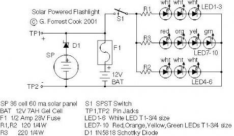
Tired of always spending money on flashlight batteries only to have them fail just when you need them? Try this simple circuit out. The white LEDs are quite bright and produce a tightly focused beam. The LED array can provide enough light to illuminate a small work or reading area at night. The red, orange, yellow and green LEDs broaden the lamp's color spectrum to produce a slighly warmer color temperature. This project would make an excellent science fair project.
The box also doubles as a 12V power source and can run other small loads such as a 12V transistor radio. This project was built with the Simpler is Better approach, the materials are common and many substitutions are possible.
(View)
View full Circuit Diagram | Comments | Reading(1254)
Solar Powered Reading Lamp
Published:2013/3/7 3:01:00 Author:Ecco | Keyword: Solar, Powered Reading Lamp
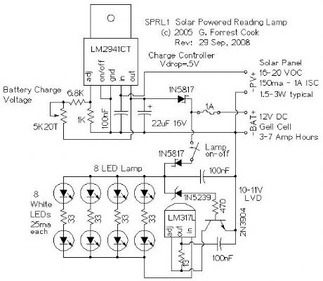
The goal of this project was to produce a self contained reading lamp that could be used by students in developing countries for reading at night. The circuit can be used for a wide variety of lighting applications.
The reading lamp consists of a small solar panel, a standard UPS style lead acid battery, and an LED circuit board. The circuit board contains a low power solar charge controller (regulator), a set of 8 white LEDs, a switch, an LED current regulator, and a low voltage disconnect circuit. The circuitry will insure a long battery life by preventing over charging and excessive discharging. The circuit was designed to work with lead acid batteries, it should also work with a string of 10 NiCd cells. Both the charge controller and LED regulator circuits can be used independently for other applications.
Newer VW and Audi automobiles come with small solar panels for keeping the battery charged in the sales lot. These panels are available on eBay for around $15 and are a perfect fit for this project. An inexpensive 12V 7AH lead acid gell-cell battery that is typically found in a computer UPS is also a good fit for this circuit. Be sure to use a new battery.
(View)
View full Circuit Diagram | Comments | Reading(1469)
| Pages:156/2234 At 20141142143144145146147148149150151152153154155156157158159160Under 20 |
Circuit Categories
power supply circuit
Amplifier Circuit
Basic Circuit
LED and Light Circuit
Sensor Circuit
Signal Processing
Electrical Equipment Circuit
Control Circuit
Remote Control Circuit
A/D-D/A Converter Circuit
Audio Circuit
Measuring and Test Circuit
Communication Circuit
Computer-Related Circuit
555 Circuit
Automotive Circuit
Repairing Circuit