
Circuit Diagram
Index 146
35V adjustable power supply 1.5 A
Published:2013/3/18 4:23:00 Author:Ecco | Keyword: 35V , adjustable power supply, 1.5 A
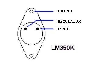
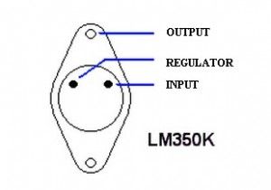
The adjustable power supply circuit shown here is just a linear power supply, a bridge rectifier and filter capacitor that it attach series voltage regulator. Furthermore, here was provided by a pair of fixed instruments that allow us to know at any time the voltage given in the output and load current used.
For this circuit to work properly the load must be at least 5 mA. Integrator has TO-3 package, known as the2N3055orBU208 citea few examples that willbe familiar toall. Below is explained how to identify each terminal of the IC LM350K : (View)
View full Circuit Diagram | Comments | Reading(1046)
Variable 4 A/25V Power Supply
Published:2013/3/18 4:22:00 Author:Ecco | Keyword: 4 A/25V Power Supply
This time we get a adjustable power supply with output voltages between 1.2 and 25V the maximum current of 4A. This is very useful for laboratory power supply or workshop power supply.
As shown in the Variable 4 Ampere /25V Power Supply scheme that the circuit consists of three stages. The first (which is formed by a transformer, bridge rectifier and an electrolytic capacitor 10000μF) is responsible for isolating and reduce the voltage, improve and filter. The second phase (consisting of, BC327 transistor integrated circuits and components attached) is responsible for providing a reference voltage which is used to determine, together with the potentiometer and top resistor, voltage applied to the driver transistor and power. It should be noted that they made a resistive and non-switched control (switching) so the voltage at the emitter is pulsed. Then we have a small output filter formed by the electrolytic capacitor and terminals.
(View)
View full Circuit Diagram | Comments | Reading(1369)
57V variable power supply up to 1.5 A
Published:2013/3/18 4:22:00 Author:Ecco | Keyword: 57V , variable power supply , 1.5 A
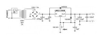
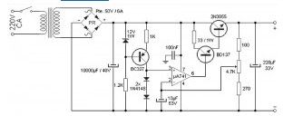
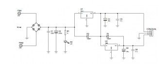
In each workshop you must have a source that is able to provide each current and voltage in a quite acceptable range of possibilities. This variable power supply device goes beyond the conventional power supply source (which rarely exceed 24V output) gives the maximum 57V with 1.5A current.
Voltage of 220V to the transformer via the power switch with built-in fluorescent light. Output voltage of 40V transformer has a improved and filtered after reaching approx. 57V. 100nF capacitors improve the performance of the source against the ripple. LM317 chip in a high voltage is responsible for regulating the output voltage through the resistor divider formed by resistor 220 ohm and potentiometer adjustments (which must be multi-turn). 10μF capacitor in the regulatory lines prevents fluctuations of regulation while the 1N5404 diode prevents the capacitor discharge that can damage integrated circuits. Two output capacitors are responsible for adequately filter the resulting voltage.
The LM317 integrated circuits has internal protection against short circuits, it has cut over temperature. By shorting out the integrated temperature rises quickly and protecting by disconnecting the output jumps up to the termination of a short circuit.
(View)
View full Circuit Diagram | Comments | Reading(1005)
Converter 3v to 5v
Published:2013/3/18 4:21:00 Author:Ecco | Keyword: Converter, 3v to 5v
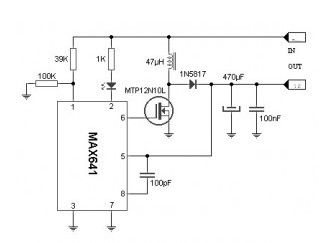
We see that almost all of which are available today in addition to the microcontroller powered by a battery. But if we do not want a 5V in many cells in series … You can use the Converter 3v to 5v circuit described here.
Based on the integrated circuits Maxim IC MAX641, this dc to dc converter ic makes it possible to provide 5V from only two AA or AAA batteries. This differs from the typical linear regulator (and inefficient 7805) which requires minimal input 8V to ensure 5V to the output (besidestoo much heat!) the eight pin small integrated circuit, similar to the 555 form, no more and no less than the surge controller switch (or Step-Up Controller SMP) which only requires a few passive components to function properly.
(View)
View full Circuit Diagram | Comments | Reading(963)
Symmetric 12V to 5V converter
Published:2013/3/18 4:19:00 Author:Ecco | Keyword: Symmetric , 12V to 5V, converter
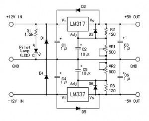
With this simple DC voltage converter circuit we can reduce 12v to 5v symmetric voltage and can use existing resources. (View)
View full Circuit Diagram | Comments | Reading(1605)
12v to 24v converter
Published:2013/3/18 4:18:00 Author:Ecco | Keyword: 12v to 24v , converter
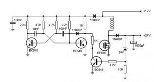
Is often you need to install some equipment in a car that works with the 24 volt source. May not be a problem for buses or trucks which have the power to work with two batteries in series. But the cars have only one battery, so it becomes necessary to raise the voltage electronically.
This 12v to 24v dc converter circuitoperates by controlling an oscillator which triggers a power transistor controlled by a Zener diode. In this way is achieved with good efficiency stabilize the output voltage.
(View)
View full Circuit Diagram | Comments | Reading(1717)
Converter 220V AC to 40kV AC
Published:2013/3/18 4:17:00 Author:Ecco | Keyword: Converter, 220V AC to 40kV AC
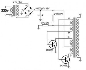
This device allows up to 40,000 volts by 220V AC. The AC to AC Converter circuit is powered from the mains through primary transformer (220-24) to isolate the network while reducing the input voltage. (View)
View full Circuit Diagram | Comments | Reading(1137)
24v to 12v converter
Published:2013/3/18 4:16:00 Author:Ecco | Keyword: 24v to 12v, converter
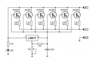
As shown, the 24v to 12v converter circuit is nothing more than an integrated adjustable voltage regulator that acts on a group of power transistors in parallel. These transistors can be said to perform heavy duty while the regulator responsible for controlling them.
Where 24 v input connector of the battery. 12V connector is the output and Gnd connector must be grounded. Of course, all the components (transistors and integrated) should be given with good heat dissipation and electrically insulated from the metal.
24v to 12v converter Adjustment :
Place the pot 10 k Ω at its maximum (fully open or 10 k Ω) and connect to the dc to dc converter output a lamp 12V / 50W. At the input connect the battery in series so the voltage is reached 24V. Place the output in parallel with the lamp tester a continuous scale with the right completion (around 50V). Begin to turn the potentiometer until the brightness of lights and tester showed 12V.
(View)
View full Circuit Diagram | Comments | Reading(5016)
Converter 9V to 13.5kV
Published:2013/3/18 4:15:00 Author:Ecco | Keyword: Converter, 9V to 13.5kV
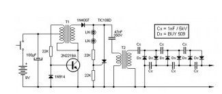
This high voltage source is formed by an inverter, around the transistor, which provides pulses of 150V to the inverter formed by the thyristor and capacitor in series with the transformer 2. This pulse output of 4.5kV to be multiplied with the network so as to achieve the output voltage of 13.5kV. Neon lamps (marked LN) form the thyristor triggering pulses.
(View)
View full Circuit Diagram | Comments | Reading(1509)
Adjustable voltage source regulator integrated circuit 7805 positive + Operational amplifier 4558
Published:2013/3/18 4:14:00 Author:Ecco | Keyword: Adjustable voltage source , regulator, integrated circuit , positive + , Operational amplifier
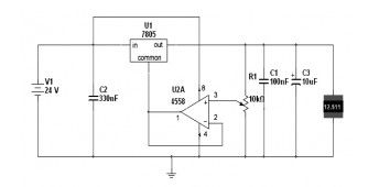
Here is a basic voltage source circuit in 7805 but adjustable, need a continuous supply unregulated, a filter capacitor, an integrated 7805 + 1 operational amplifier 4558.
(View)
View full Circuit Diagram | Comments | Reading(1983)
Sega Game Gear Power supply
Published:2013/3/18 4:13:00 Author:Ecco | Keyword: Sega Game Gear, Power supply
Here is a power supply circuit for sega game gear for the additional collection of your circuit. For a more complete explanation can be found on the website http://hardware.speccy.org.
(View)
View full Circuit Diagram | Comments | Reading(2381)
Power Supply source +5 Vdc +12 Vdc
Published:2013/3/18 4:11:00 Author:Ecco | Keyword: Power Supply source, +5 Vdc +12 Vdc
This power supply circuit shows a steady source of continuous power supply combined with an output of +5 VDC and +12 VDC to ground, it is estimated for designing a current of about 900mA Max, enough to power any digital circuit with a relay output,that must be taken into account is the cascade design makes total consumption is the sum of the currents provided by the two outputs. Please note that the regulator should be equipped with a heat sink.
(View)
View full Circuit Diagram | Comments | Reading(831)
Power supply 4.5 A with 3 LM317 in parallel
Published:2013/3/18 4:10:00 Author:Ecco | Keyword: Power supply, 4.5 A
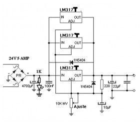
This lm317 variable power supply can supply a voltages from 1.2V to 30V with a current 3 amperes, just as the title of this series based on LM317T voltage regulator, the LM317T regulator provide around 1.5 amperes on the heatsink, so by installing a parallel two or three of them will get a voltage source capable of providing 3 amperes. Obviously this also depends on the transformer used.
TheLM317T regulators are able to withstand short circuit at the output of the source and not so easily destroyed like LM350K or LM338K regulators, the regulator IC used in this circuit using ST manufacturing company and have shown positive result.
(View)
View full Circuit Diagram | Comments | Reading(8655)
Simple Symmetrical Power supply +25v -25v
Published:2013/3/18 2:10:00 Author:Ecco | Keyword: Symmetrical Power supply
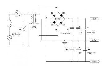
This symmetrical unregulated power supply is used to feed the audio amplifier based on LM1875 amplifier module National Semiconductor. With symmetrical 30V DC source the amplifier capable of delivering up to 30W of power using 8 ohm load.
The diagram above shows how the DC +25 V and-25V DC can be obtained. Ready to provide power to two stereo amplifiers, one 80VA transformer with 240V input and 36V output, with the center tap is used. The output of the transformer secondary repaired using four 1N5401 diodes and filtered through four electrolytic capacitors. A fuse and a varistor connected to the main circuit protection against voltage spikes.
(View)
View full Circuit Diagram | Comments | Reading(1401)
Stereo Pre-amplifier + Tone Control Circuit based TDA1524A
Published:2013/3/18 2:05:00 Author:Ecco | Keyword: Stereo , Pre-amplifier, + Tone Control
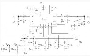
This is the circuit diagram of stereo preamplifier which built based a compact IC TDA1524A. Tone control circuit module is included in this preamplifier circuit, so you can connect the output channels directly to stereo power audio amplifier circuit.
(View)
View full Circuit Diagram | Comments | Reading(3061)
1W Audio Amplifier Circuit based TDA7052
Published:2013/3/18 2:03:00 Author:Ecco | Keyword: 1W , Audio Amplifier
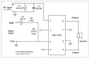
This is the 1 Watt power audio amplifier based Phillip IC TDA7052. The circuit can be used for small audio amplification. The circuit is very simple and easy to build. It only required 5 external components to support the main power IC. Ideal supply voltage is 6V to 12 VDC. R2 is a linear potensiometer to adjust the volume.
(View)
View full Circuit Diagram | Comments | Reading(2211)
RF Amplifier Circuit : 1 Watt 2.3GHz based MRF2001
Published:2013/3/18 2:02:00 Author:Ecco | Keyword: RF Amplifier , 1 Watt, 2.3GHz
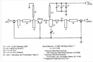
This the 1W RF amplifier circuit which used a common-base power transistor MRF2001, a class C amplifier. This RF amplifier delivers about 1 Watt power output with 8-dB minimum gain at 24V voltage supply. The frequency can be tuned from 2.25GHz to 2.35GHz. Applications include microwave communications equipment and other systems that require medium-power narrow-band amplification. The amplifier circuitry consists almost entirely of distributed microstrip elements.
(View)
View full Circuit Diagram | Comments | Reading(1439)
1W Power Amplifier with Electronic Volume Control based TDA8551
Published:2013/3/18 2:01:00 Author:Ecco | Keyword: 1W ower Amplifier, Electronic Volume Control
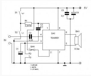
The TDA8551 chip by Philips is a bridge amplifier with output power of 1 watt at a supply voltage of 5V. In this case, current consumption in the silent mode is only 10mA. The chip is made in 8-pin package and requires no heat sink, it can be used in a variety of small devices. Chip is equipped with thermal protection, has an internal delay circuit connecting the load – so that when you turn, you hear a wheeze other wonderful music transients. This chip also built-in an electronic volume control.
(View)
View full Circuit Diagram | Comments | Reading(1907)
2.6W Two Channel Amplifier based MAX9751
Published:2013/3/18 1:58:00 Author:Ecco | Keyword: 2.6W, Two Channel, Amplifier
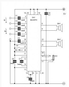
This amplifier circuit based MAX9751 IC which work on the 5 Volt voltage, unipolar, and a 2.6 Watt power output per channel. In addition, there is a headphone output with separate amplifier and the input selector inputs – you can connect two sources of signal.
(View)
View full Circuit Diagram | Comments | Reading(1022)
1.4W Stereo Power Amplifier Circuit based TDA8552
Published:2013/3/18 1:55:00 Author:Ecco | Keyword: 1.4W , Stereo Power Amplifier
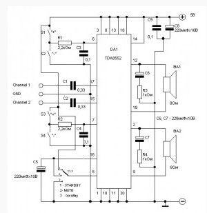
A few more words on the chip. This is a bridge amplifier class AB integrated into the protection against overheating, short circuit protected outputs, suppression of inrush current when you turn on and off the amplifier. The only difference – a little more power output – 1.4 watts per channel. But nevertheless, it also does not require a heat sink and can be used anywhere.
(View)
View full Circuit Diagram | Comments | Reading(1540)
| Pages:146/2234 At 20141142143144145146147148149150151152153154155156157158159160Under 20 |
Circuit Categories
power supply circuit
Amplifier Circuit
Basic Circuit
LED and Light Circuit
Sensor Circuit
Signal Processing
Electrical Equipment Circuit
Control Circuit
Remote Control Circuit
A/D-D/A Converter Circuit
Audio Circuit
Measuring and Test Circuit
Communication Circuit
Computer-Related Circuit
555 Circuit
Automotive Circuit
Repairing Circuit