
Circuit Diagram
Index 159
TOUCH SWITCH and TOUCH ON-OFF Circuit
Published:2013/3/5 20:55:00 Author:Ecco | Keyword: TOUCH SWITCH , TOUCH ON-OFF
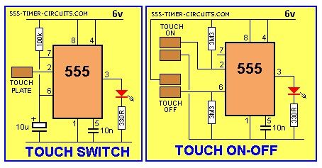
The Touch Switch circuit will detect stray voltages produced by mains voltages and electrostatic build-up in a room. In the first circuit, pin 2 must see a LOW for the circuit to activate. If sufficient static voltage is detected by the plate, the chip will change state. If not, you will need to touch the plate and the 0v rail. In the second circuit, two touch plates are provided and the resistance of your finger changes the voltage on pin 2 or 6 to toggle the 555.
(View)
View full Circuit Diagram | Comments | Reading(6748)
TILT SWITCH Circuit
Published:2013/3/5 20:53:00 Author:Ecco | Keyword: TILT SWITCH

The output is LOW at start-up due to the capacitor on pin 4. When the mercury switch closes, the output goes HIGH and remains HIGH until the reset button is pressed. This circuit is called a LATCH.
(View)
View full Circuit Diagram | Comments | Reading(1142)
STUN GUN Circuit
Published:2013/3/5 20:52:00 Author:Ecco | Keyword: STUN GUN
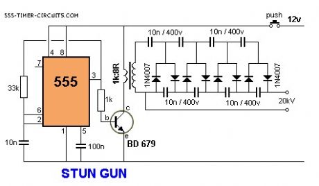
This circuit produces a very high voltage and care must be used to prevent getting a nasty shock.The transformer can produce over 1,000v and the 8-stage multiplier can produce up to 20,000v.
(View)
View full Circuit Diagram | Comments | Reading(4887)
STEPPER MOTOR CONTROLLER TE555-1 Circuit
Published:2013/3/5 20:50:00 Author:Ecco | Keyword: STEPPER MOTOR , CONTROLLER
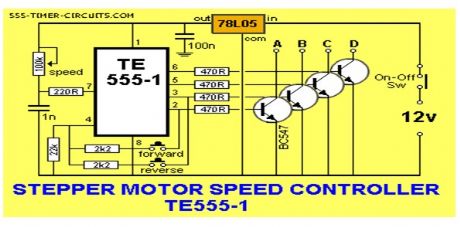

The direction of rotation is determined by the FORWARD and REVERSE switches and the motor does not take any current when a switch is not pressed.
(View)
View full Circuit Diagram | Comments | Reading(5807)
SIREN 100dB Circuit
Published:2013/3/5 20:46:00 Author:Ecco | Keyword: SIREN 100dB
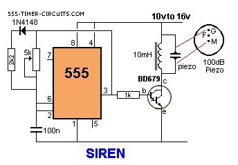
This is a very loud siren and if two or more piezo's are located in a room, the burglar does not know where the sound is coming from. A robber will not stay anywhere with an ear-piercing sound as he cannot hear if someone is approaching. It's the best deterrent you can get. The F contact on the piezo is feedback and is not needed in this circuit.
(View)
View full Circuit Diagram | Comments | Reading(1357)
SERVO TESTER Circuit
Published:2013/3/5 20:45:00 Author:Ecco | Keyword: SERVO TESTER
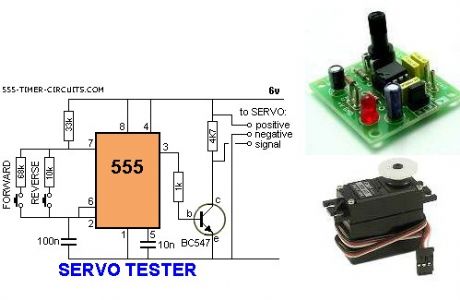
This circuit can be used to manually turn a servo clockwise and anti-clockwise. By pushing the forward or reverse button for a short period of time you can control the rotation of the servo. It will also test a servo. Here is a photo of a kit from Cana Kit for $10.00 plus postage (it is a slightly different circuit) and a motor and gearbox, commonly called a servo. The output shaft has a disk or wheel containing holes. A linkage or push-rod is fitted to a hole and when the disk rotates, the shaft is pushed and pulled. The shaft only rotates about 180?to actuate flaps or ailerons etc.
(View)
View full Circuit Diagram | Comments | Reading(6704)
RAIN ALARM Circuit
Published:2013/3/5 20:39:00 Author:Ecco | Keyword: RAIN ALARM
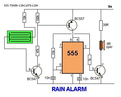
This circuit consumes no current until moisture is detected on the rain plate.
(View)
View full Circuit Diagram | Comments | Reading(2216)
POLICE SIREN Circuit
Published:2013/3/5 20:37:00 Author:Ecco | Keyword: POLICE SIREN
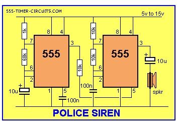
The Police Siren circuit uses two 555's to produce an up-down wailing sound. The first 555 is wired as a low-frequency oscillator to control the VOLTAGE CONTROL pin 5 of the second 555. The voltage shift on pin 5 causes the frequency of the second oscillator to rise and fall.
(View)
View full Circuit Diagram | Comments | Reading(1219)
Non-contact AC measuring circuit
Published:2013/3/5 0:45:00 Author:Ecco | Keyword: Non-contact, AC, measuring circuit
Non-contact AC measuring circuit is shown as figrue.
(View)
View full Circuit Diagram | Comments | Reading(2552)
Photosensitive element test circuit
Published:2013/3/4 3:12:00 Author:Ecco | Keyword: Photosensitive element, test circuit
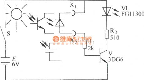
Photosensitive element test circuit is shown as figure.
(View)
View full Circuit Diagram | Comments | Reading(1249)
LED- parallel digital tube LED static display circuit (common anode)
Published:2013/3/5 0:43:00 Author:Ecco | Keyword: LED, parallel digital tube, static display , common anode
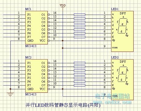
LED- parallel digital tube LED static display circuit (common anode) is shown as figure.
(View)
View full Circuit Diagram | Comments | Reading(1188)
LED - serial LED digital tube dynamic scanning display circuit ( common anode )
Published:2013/3/5 0:42:00 Author:Ecco | Keyword: LED - serial, LED digital tube, dynamic scanning , display circuit , common anode
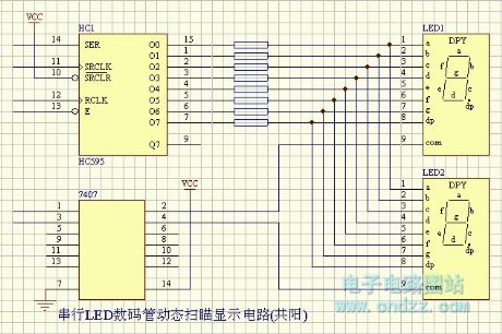
LED - serial LED digital tube dynamic scanning display circuit ( common anode ) is shown as figure.
(View)
View full Circuit Diagram | Comments | Reading(1037)
LED - serial LED digital tube dynamic scanning display circuit ( common cathode )
Published:2013/3/5 0:41:00 Author:Ecco | Keyword: LED - serial, LED digital tube , dynamic scanning , display circuit , common cathode
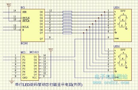
LED - serial LED digital tube dynamic scanning display circuit ( common cathode ) is shown as figure.
(View)
View full Circuit Diagram | Comments | Reading(1096)
POLICE LIGHTS Circuit
Published:2013/3/5 0:33:00 Author:Ecco | Keyword: POLICE LIGHTS
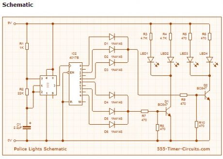
This circuit uses a 555 timer which is setup to both runn in an Astable operating mode. This generates a continuous output via Pin 3 in the form of a square wave. When the timer's output changes to a high state this triggers the a cycle on the 4017 4017 decade counter telling it to output the next sequential output high. The outputs of the 4017 are connected to the LEDs turning them on and off.
(View)
View full Circuit Diagram | Comments | Reading(3284)
MUSIC BOX Circuit
Published:2013/3/5 0:33:00 Author:Ecco | Keyword: MUSIC BOX
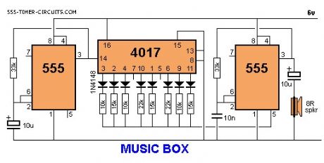
This circuit produces 10 different tones and by selecting suitable values to change the voltage on pin 5, the result can be quite pleasing. Note: the two unused outputs of the 4017 produce a tone equal to that produced by the 555 when pin 5 has no external control voltage.
(View)
View full Circuit Diagram | Comments | Reading(1775)
MOTOR PWM Circuit
Published:2013/3/5 0:32:00 Author:Ecco | Keyword: MOTOR PWM
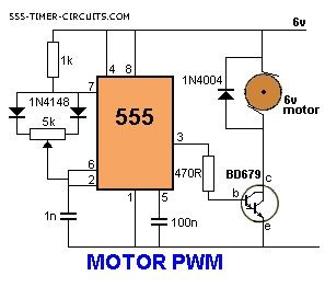
The speed of a motor can be adjusted by this circuit, from 5% to 95%.
(View)
View full Circuit Diagram | Comments | Reading(1098)
MOSQUITO REPELLER Circuit
Published:2013/3/5 0:31:00 Author:Ecco | Keyword: MOSQUITO REPELLER
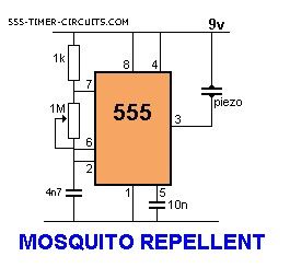
This circuit produces a tone above the human audible range and this is supposed to keep the mosquitoes away. You need a piezo diaphragm that will respond to 15kHz and these are very difficult to find.
(View)
View full Circuit Diagram | Comments | Reading(3106)
MODEL RAILWAY TIME Circuit
Published:2013/3/5 0:30:00 Author:Ecco | Keyword: MODEL RAILWAY, TIME Circuit
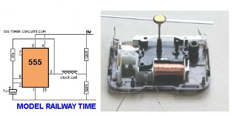
Here is a circuit that will convert any clock mechanism into Model Railway Time. For those who enjoy model railways, the ultimate is to have a fast clock to match the scale of the layout. This circuit will appear to make time fly by turning the seconds hand once every 6 seconds. The timing can be adjusted by changing the 47k. The electronics in the clock is disconnected from the coil and the circuit drives the coil directly. The circuit takes a lot more current than the original clock (1,000 times more) but this is one way to do the job without a sophisticated chip.
(View)
View full Circuit Diagram | Comments | Reading(1115)
MACHINE GUN Circuit
Published:2013/3/5 0:27:00 Author:Ecco | Keyword: MACHINE GUN
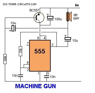
This circuit produces a sound very similar to a machine gun:
(View)
View full Circuit Diagram | Comments | Reading(1330)
LED DIMMER Circuit
Published:2013/3/5 0:25:00 Author:Ecco | Keyword: LED DIMMER
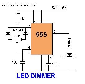
This circuit will adjust the brightness of one or more LEDs from 5% to 95%.
(View)
View full Circuit Diagram | Comments | Reading(1824)
| Pages:159/2234 At 20141142143144145146147148149150151152153154155156157158159160Under 20 |
Circuit Categories
power supply circuit
Amplifier Circuit
Basic Circuit
LED and Light Circuit
Sensor Circuit
Signal Processing
Electrical Equipment Circuit
Control Circuit
Remote Control Circuit
A/D-D/A Converter Circuit
Audio Circuit
Measuring and Test Circuit
Communication Circuit
Computer-Related Circuit
555 Circuit
Automotive Circuit
Repairing Circuit