
Circuit Diagram
Index 144
Audio short pulse sequence circuit
Published:2013/3/19 2:12:00 Author:Ecco | Keyword: Audio, short pulse sequence
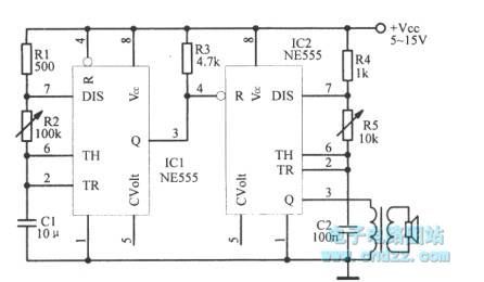
Audio short pulse sequence circuit is shown as figure.
(View)
View full Circuit Diagram | Comments | Reading(943)
Sine wave-square wave converter circuit
Published:2013/3/19 2:07:00 Author:Ecco | Keyword: Sine wave, square wave , converter
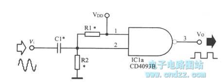
Sine wave-square wave converter circuit is shown as figure.
(View)
View full Circuit Diagram | Comments | Reading(6288)
Precision pulse oscillator with frequency demodulation circuit LM567 and multi-stage divider MPl826
Published:2013/3/19 2:00:00 Author:Ecco | Keyword: Precision pulse oscillator , frequency demodulation , multi-stage divider
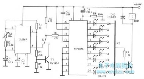
Precision pulse oscillator with frequency demodulation circuit LM567 and multi-stage divider MPl826 is shown as figure.
(View)
View full Circuit Diagram | Comments | Reading(4103)
Two-phase clock oscillator with 1MHz highest frequency
Published:2013/3/19 2:11:00 Author:Ecco | Keyword: Two-phase clock , oscillator , 1MHz highest frequency
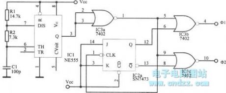
Two-phase clock oscillator with 1MHz highest frequency is shown as figure.
(View)
View full Circuit Diagram | Comments | Reading(936)
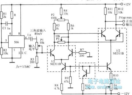
Franklin push-pull electric compressive controlled oscillator
Published:2013/3/19 1:57:00 Author:Ecco | Keyword: Franklin, push-pull, electric compressive controlled , oscillator
Franklin push-pull electric compressive controlled oscillator is shown as figure.
(View)
View full Circuit Diagram | Comments | Reading(1622)
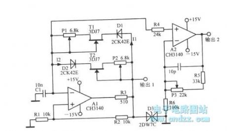
Precision clamp ultra-low frequency triangle wave oscillator
Published:2013/3/19 1:55:00 Author:Ecco | Keyword: Precision, clamp , ultra-low frequency, triangle wave , oscillator
Precision clamp ultra-low frequency triangle wave oscillator is shown as figure.
(View)
View full Circuit Diagram | Comments | Reading(1218)
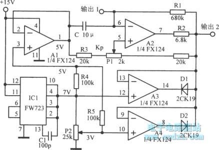
Square wave-triangle wave oscillator
Published:2013/3/19 1:52:00 Author:Ecco | Keyword: Square wave, triangle wave, oscillator
Square wave-triangle wave oscillator is shown as figure.
(View)
View full Circuit Diagram | Comments | Reading(911)
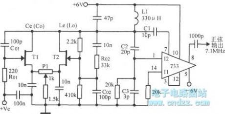
Triangle wave-sine wave oscillator
Published:2013/3/19 1:53:00 Author:Ecco | Keyword: Triangle wave, sine wave, oscillator
Triangle wave-sine wave oscillator is shown as figure.
(View)
View full Circuit Diagram | Comments | Reading(1662)
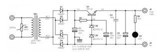
Adjustable Regulated Power Supply 0-15V / 1A
Published:2013/3/18 22:11:00 Author:Ecco | Keyword: Adjustable, Regulated Power Supply , 0-15V, 1A
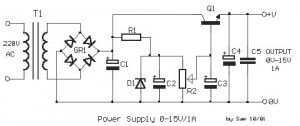
This is the schematic diagram of adjustable power supply which the voltage output can be vary from 0V up to 15V with fixed current output maximum of 1A. The circuit is very simple and easy to build, finding the components is easy and inexpensive. The output voltage is stabilized and regulated in the range of 0V to +15 V, supplied with a maximum current of 1 A.The potensiometer R2 is used to adjust the voltage output. The Q1 is an old type power transistor which commonly used to amplify an input, and this transistor needs to be on heatsinks, as it will be heat up when working continuously in the region of maximum current. The type of transformer is standard on the market. (View)
View full Circuit Diagram | Comments | Reading(1231)
Choosing a PC Power Supply by Power Comparison
Published:2013/3/18 22:09:00 Author:Ecco | Keyword: PC Power Supply, Power Comparison

Power supply is probably the most computer components are often overlooked by PCs buyers. However, this component is very important : such as when the power is insufficient or if the voltage is too unstable, the power supply can cause crashes or reboots the machine. Even worse, if power is working too hard and / or in poor quality, maybe just by turning on the computer may cause damage to most of the components: motherboard, CPU, hard drive and a DVD player! Note that branded manufacturers are also found in the market often overlook the power supply in order to reduce the selling price of the computer. Most buyers assume the power supply is not important, some unscrupulous manufacturers introduce large-sized power and poor quality for their machines.
(View)
View full Circuit Diagram | Comments | Reading(912)
Single Output Power Supply +1.25 V to 28 V / 1A Based on LM317
Published:2013/3/18 22:08:00 Author:Ecco | Keyword: Single Output, Power Supply , +1.25 V to 28 V / 1A
The voltage regulator used here (LM317) theoretically can provide 1A maximum current. Its heating depends on two factors: the potential difference between its input and output, and the current passing through it (which is what the charge will apply). If the potential difference is important, you can not make out much power to the controller. At the same time, the controller must have its input voltage of at least 3 volts higher than the output voltage (for 12V regulated output, the input voltage must be at least 15V). Knowing that the regulator accepts a voltage as high as 37V input, you will find what is reasonable between these two limits, depending on the desired current output. In summary, avoid using an input voltage too high for a low output voltage if you really do charge to 1A power supply, limit yourself to 5V or 6V differential. In order to to work the regulator in the power range for which it is said, it is imperative to provide a sufficiently large cooling radiator.
(View)
View full Circuit Diagram | Comments | Reading(978)
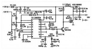
Car DC to DC Converter for laptops
Published:2013/3/18 22:07:00 Author:Ecco | Keyword: Car , DC to DC, Converter, laptops
Laptops today are the what is called notebook computers, which now is becoming popular. Laptops can be brought into the bag making it suitable for business trips. And even as the “home entertainment center” laptop is more convenient, because it takes a little space. However, in my opinion, there is one very important which become shortcomings – most laptops which powered by an electric voltage of 19V, making it impossible for them to direct the power to an integrated network vehicle (12-14V). It is very important, especially when laptop battery capacity is not more than two hours in active mode. And what if you, at some object in the whole day want to process some data, but no other useful sources of electricity?
This is a description of the relatively simple psu laptop circuit adapter (laptop DC-DC converter), which increases the voltage-board vehicle network to 19V, needed to supply the laptop. And maintain this voltage stable.
The adapter is based on chip LM3524, which is a high-frequency switching DC-DC converter with pumped inductance and output current up to 200mA, the output current which, in this scheme, will increased to 3.5-4A using a powerful transistor switch (on transistors VT1 and VT2).
(View)
View full Circuit Diagram | Comments | Reading(1118)
5000VDC Output from 230 VAC Input, with Diode Voltage Multiplier / Capacitor
Published:2013/3/18 22:07:00 Author:Ecco | Keyword: 5000VDC Output, 230 VAC Input, Diode Voltage Multiplier , Capacitor
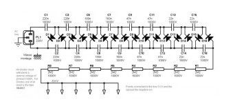
The diagram shows a set of cell diode / capacitor connected in series, each set of increasing voltage 300 V.The voltage 230 V applied to the input of voltage multiplier, it gradually increased in each set of diodes / capacitors. Which eventually reached a value of more than 5000 V at the anode of the last diode (D16). Voltage rise gradually, as the capacitor discharged at the time of power up: voltage 5000 V was obtained after a few seconds.
(View)
View full Circuit Diagram | Comments | Reading(2335)
Dual Polarity Power Supply +/- 15V based Transistors
Published:2013/3/18 22:06:00 Author:Ecco | Keyword: Dual Polarity , Power Supply, +/- 15V , Transistors
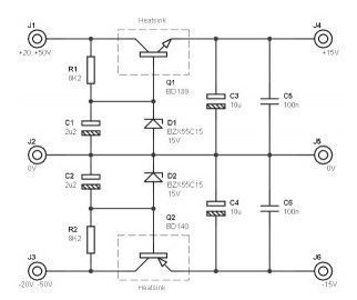
This Dual supply circuit is suitable for installation of power analog (audio or measurement), it provides a bipolar voltage with voltage source between 20 and 50 V (in audio power amp, for example). Regulated output voltage is 15V, but can be adjusted from + /-12V or + /-18V by simply changing two components. The maximum output current must not exceed 100 mA each branch.
If you ask, where the transformer and diode rectifier?This circuit is intended to be transplanted into an existing circuit (eg audio amp), which already provides symmetric voltage between + /-20V and + /-50V.
(View)
View full Circuit Diagram | Comments | Reading(1867)
Dual Output Power Supply +/-53V / 3A based on Transistors
Published:2013/3/18 21:21:00 Author:Ecco | Keyword: Dual Output Power Supply, +/-53V / 3A, Transistors
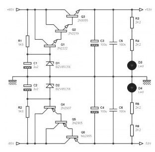
This is the circuit diagram of dual output power supply +/-53V / 3A based on transistors. This circuit has been designed for audio amplifier power supply requires a symmetrical + / -53 V (+ / -56 V maximum). The role of the circuit part presented here is to lower the voltage of both positive and negative lines of + / -65 V for non-hazardous + / -53 V for the amplifier, while allowing the current to 3 A in continuous operation.
The diagram above, based on the same principle as the previous circuit Dual supply + /-15V-based transistors, and is based on the use of common components. Differences of Dual supply + /-15V-based transistors, lies only in the number of transistors connected in cascade to allow high output currents while not requiring a zener diode of 10 W for output voltage stabilization. The main advantage of this type of configuration is to have a high current gain. The second point is not important in this case. Power dissipation in the ‘final’ two transistor Q3, and Q6 to 3 A output current, is about 36 W, which require a large heatsink. Transistors Q2 and Q5 is recommended fitted fin heat sink (for TO5 case).
(View)
View full Circuit Diagram | Comments | Reading(1626)
Single Power Supply with Soft Start
Published:2013/3/18 21:20:00 Author:Ecco | Keyword: Single Power Supply , Soft Start
This Single power supply with soft start circuit which presented here has a simple concept, small power, smooth voltage. This power supply voltage is actually used for control kit K8003 © VELLEMAN, which allows to smooth ignition the exterior halogen spotlights (500 Watt) or interior spotlights (bathroom lighting for example), blackout is instantaneous. You must mount this circuit in the housing fully insulated and waterproof.
The circuit is based on the LM317, it is possible to varying the voltage between 1.25 V to 27 V depending on the voltage applied to the input (input voltage must be greater than 3 volts from the output circuit).
Increasing the value of the components (R and / or C) resulted in an increase in the rise time of 1.25 V to a preset voltage with P1. By the number shown in the component list, the time is ± 3 seconds for 10 V Usort.
(View)
View full Circuit Diagram | Comments | Reading(2529)
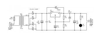
Isolated Power Supply +5 V to +15 V, 500 mA
Published:2013/3/18 21:19:00 Author:Ecco | Keyword: Isolated Power Supply , +5 V to +15 V, 500 mA
The Isolated Power supply +5 V to +15 V, 500 mA diagram represents a single control block, knowing that all are identical. It is truly classic, and is based on the use of common components. The Isolated Power supply +5 V to +15 V, 500 mA circuitdescribed belowis a “modification”that is designedtoaccommodateall the modulesona singlecircuit board.
Both terminals J1 and J2 (AC1 and AC1 ‘) is from secondary AC transformer. The AC voltage undergoes a wave rectification through four diodes D1 to D4 connected in a bridge, this voltage then filtered by capacitor C1. Values used in the diagram is 1000UF, may be increased to 2200 uF if the output ripple proved too big for your application. Voltage regulation is entrusted to the LM317 regulator IC, is slightly higher quality than its counterparts 78xx, but especially with the advantage that can be adjusted and able to work well over a wide output range. The capacitor C2 is optional, but it contributes significantly to the reduction of output ripple, therefore it is highly recommended. Two diodes D6 and D7 is also optional and only play a protective role is not always necessary at low currents. he output voltage is determined by the value of two resistors forming a voltage divider between output and ground, and whose midpoint is connected to the pin fitting U1.
(View)
View full Circuit Diagram | Comments | Reading(947)
Dual Power Supply with Soft Power Switch
Published:2013/3/18 21:18:00 Author:Ecco | Keyword: Dual Power Supply , Soft Power Switch
This power supply circuit brings together a dual polarity power supply and soft power to a power transformer (to supply a large amplifier for example) on the same board.
The regulator circuit is performed by a pair of 79xx and 78XX (XX = 12 to 24), if the current requirement does not exceed 200 mA, the heatsink is not needed here (but available in the printed circuit board). Tthis circuit part provides power to devices such as amplifiers (preamplifier, fans, the protection module etc. …).
Soft power for a large transformer is made by taking the series resistance of 100 ohms/10 watt or two resistors 47 ohm / 5 watts in the primary circuit, the resistance is shorted by the relay after ± 1.5 seconds. This avoids a sudden use of the current during power up. A Zener diode can be adjusted to allow the use of various voltage relay.
(View)
View full Circuit Diagram | Comments | Reading(1335)
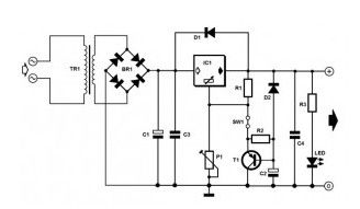
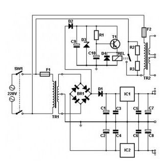
24V / 2A DC Power Supply
Published:2013/3/18 21:17:00 Author:Ecco | Keyword: 24V / 2A DC Power Supply
The 24 volts power supply circuit is very simple. It uses a zener diodes and Darlington transistors type TIP122. Output voltage is set at 24 V with 2 amperes current output.
Lowering the voltage 230 V sector is provided by the transformer TR1, whose secondary voltage is 24 V. Available voltage after rectification and filtering is the order of 32 V to 34 V (depending on transformer and voltage).
Electrolytic capacitor C1 provides filtering rectified voltage to obtain the required output voltage. Its value depends on the maximum output current that you want to get, 4700 UF set here will allow you to simply filter 2 A output current. You can reduce it to 2200 uF if you dont need more than 1 A. The proposed circuit allows the implementation of one or two radial capacitors 2200UF-4700 UF, the choice is yours depending on the size of the capacitor that you can get.
The voltage stabilization is entrusted to a zener diode, which is supported by a Darlington transistor for output current capability greater (TIP122 transistor carries a collector current of 5 A continuous, so this is fine). In fact, if you look at the diagram, you find that there are two zener diodes instead of one. This choice allows you to change easily the output voltage by choosing other values of zener diodes. For this model, It used a 12 volt zener (BZX55C12) and a 13-V (BZX55C13), so that the output voltage is close to 24 V output current max. The output voltage depends a little on current consumption, this is quite normal for this type of scheme.
The power dissipated by the transistor Q1 is connected to the voltage difference that exists between its collector (regulated voltage of about 32 V) and its emitter (regulated voltage of 24 V), and supply output current (2 A max). Therefore, in 16 W at full capacity, which requires the use of cooling radiators in Q1.
(View)
View full Circuit Diagram | Comments | Reading(1487)
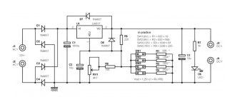
Mobile NiCd Charger
Published:2013/3/18 21:14:00 Author:Ecco | Keyword: Mobile NiCd Charger
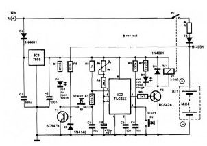
This mobile battery charger is designed primarily in order to give model enthusiasts the opportunity of charging their Nicad batteries from a car battery out in the open.
When the NiCd charger circuit is connected to the car battery, D2 lights only if the Nicad to be charged has been connected with correct polarity. For that purpose, the + terminal of the Nicad battery is connected to the base of T1 via R8. Because even a discharged battery provides some voltage, Ti is switched on and D2 lights.
Pressing thestart switchS1will have an effectonlyif ithas thecorrectpolarity. If so, the collector voltage of T1 is virtually zero so that monostable IC2 is triggered by S1. The output, pin 3, of this CMOS timer then becomes high, T2 is switched on and relay Rel is energized. Charging of the Nicad battery, via R5 and D6, then begins and charging indicator D4 lights. During the charging, C4 is charged slowly via Pl and R4. The value of these components determines the mono time of IC2 and thus the charging period of the Nicad battery. With values as shown in the diagram, that period can be set with P1 to between 26 and 33 min. Notice that this time is affected by the leakage current of C4; use a good-quality capacitor here. The charging can be interrupted with reset switch S2.
(View)
View full Circuit Diagram | Comments | Reading(1427)
| Pages:144/2234 At 20141142143144145146147148149150151152153154155156157158159160Under 20 |
Circuit Categories
power supply circuit
Amplifier Circuit
Basic Circuit
LED and Light Circuit
Sensor Circuit
Signal Processing
Electrical Equipment Circuit
Control Circuit
Remote Control Circuit
A/D-D/A Converter Circuit
Audio Circuit
Measuring and Test Circuit
Communication Circuit
Computer-Related Circuit
555 Circuit
Automotive Circuit
Repairing Circuit