
Circuit Diagram
Index 149
18 ~ 60MHz third harmonic oscillator
Published:2013/3/15 3:07:00 Author:Ecco | Keyword: 18 ~ 60MHz, third harmonic, oscillator
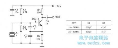
18 ~ 60MHz third harmonic oscillator is shown as figure.
(View)
View full Circuit Diagram | Comments | Reading(1548)
15 ~ 65MHz third harmonic oscillator
Published:2013/3/15 2:59:00 Author:Ecco | Keyword: 15 ~ 65MHz, third harmonic oscillator
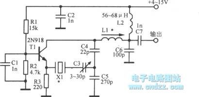
15 ~ 65MHz third harmonic oscillator is shown as figure.
(View)
View full Circuit Diagram | Comments | Reading(1169)
LED on -off time controlled oscillator
Published:2013/3/15 3:06:00 Author:Ecco | Keyword: LED , on -off time, controlled oscillator
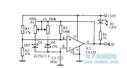
LED on -off time controlled oscillator is shown as figure.
(View)
View full Circuit Diagram | Comments | Reading(874)
High quality monoblock power amplifier
Published:2013/3/14 3:26:00 Author:Ecco | Keyword: high quality, monoblock power amplifier
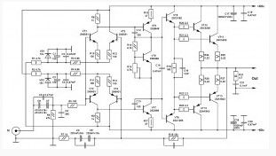
This high quality monoblock power amplifier is a good transistor amplifier circuits. And with a simple high quality power amplifier circuit that can produce good sound quality. This amplifier is built on the classic symmetrical scheme with output stage operates in class AB and has a pretty good sound, with no complicated setup and scarce components.Correctly assembled amplifier is immediately reduced to setting the quiescent current setting. It put up trimmer R15. First, put a minimum quiescent current and allow the amplifier to work for 15-20 minutes on medium power. After this input shorting switch off and expose the acoustics of a quiescent current of 50-80 mA. It measures the decline in voltage on the resistors R24 – R27, it should be in the range 0,22-0,36 V. The voltage on the right and the left arm might be slightly different. The scheme is desirable to use film capacitors K73-17 or foreign analogues, C8, C12, C13 – can be ceramics. Weekends and proximity with transistors it is desirable to choose pairs, well, at least one of the parties, as mutually desirable to select and VT1, VT3 and VT2, VT4. In the photo resistors R1 and R2 at 0.25 W, and later they were replaced by 2W, although enough of resistors and 0.5 Watts. For transistors VT5, VT7 made a small aluminum heatsink. The dimensions of the PCB 140h80mm.
(View)
View full Circuit Diagram | Comments | Reading(4264)
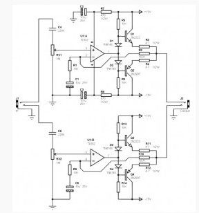
Monoblock Car Amplifier TDA7294
Published:2013/3/14 3:25:00 Author:Ecco | Keyword: Monoblock Car Amplifier
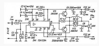
Monoblock Car Amplifier circuit TDA7294 is based on an article “Improving the power amplifier IC TDA7294″ Journal of the radio, № 11 2005. This mono car amplifier has a sufficiently high reliability, high capacity, high-quality bass. Monoblock Car Amplifier circuit is shown above. The difference from the original circuit only in the output transistor using a better replacement.All non-electrolytic capacitors, except for C2, film, 1 uF input capacitance can be replaced 2.2uF. Power of resistors are selected using a 0.25W, although 0.125W is still insufficient. Output transistors of Monoblock Car Amplifier mounted bent and pressed so that their position parallel to the board, to remove heat, a heatsink for transistor 2SC5200 and 2SA1943 and is required. Do not forget to provide insulation and thermal paste between the heatsink and transistors. Inductor L1 frameless, coiled wire diameter of 1 mm in two layers and contains 25 turns, the inner diameter of 5 mm.
(View)
View full Circuit Diagram | Comments | Reading(3499)
Headphone Audio Amplifier based Two Transistors
Published:2013/3/14 3:23:00 Author:Ecco | Keyword: Headphone Audio Amplifier, Two Transistors
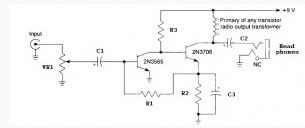
TheHeadphone audio amplifier based two Transistors circuit is very simple and easy to construct, the main component is built with only two transistors 2N3565 and 2N3706.Headphone Audio Amplifier Power supply can use a 9V battery. Output Headphone Amplifier can be connected with a 32 or 64 ohm headphones.
(View)
View full Circuit Diagram | Comments | Reading(1612)
Motorola Hi-Fi Power Amplifier 20W to 80W RMS
Published:2013/3/14 3:22:00 Author:Ecco | Keyword: Motorola , Hi-Fi Power Amplifier, 20W to 80W RMS
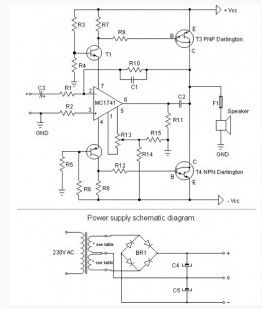
This Motorola Hi-Fi power amplifier circuit are very simple, low cost, and Hi-Fi quality power amplifier. You can build this circuit in 5 options power output, as shown in the table (from 20W, 25W, 35W, 50W, 80W RMS).
The first thing you should do, is to measure the end transistors (T3 and T4) amplifying coefficient, the hfe or â. If bigger than 30 %, the amplifier would not give a clean sound. You can used MJ3001 and MJ2501 transistors, and this amplifying coefficient was around 5%.
Just before the first “turning on” you must short circuit the inputs of the amp, and put a mA-meter on the output, than turn the amplifier on, and tune the R13 pot, to decrease the DC current on the output, nearly 0, or in a lucky situation to zero. In this example, it was able to decrease it to 10 uA.
(View)
View full Circuit Diagram | Comments | Reading(2573)
General Purpose 10 Watt Audio Amplifier Circuit
Published:2013/3/14 3:21:00 Author:Ecco | Keyword: General Purpose , 10 Watt, Audio Amplifier
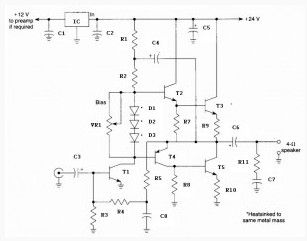
This circuit is a general purpose 10-W power audio amplifier for medium power amplifier or use a modulation in the AM transmitter. For higher power up to 30 W can be obtained by increasing the voltage and change the bias resistor value.
(View)
View full Circuit Diagram | Comments | Reading(1638)
20 Watt Power Amplifier based TDA2005
Published:2013/3/14 3:19:00 Author:Ecco | Keyword: 20 Watt, Power Amplifier
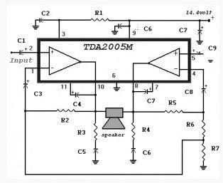
This 20 Watt Power Amplifier circuit is used as a car audio amplifier. Its main component is 20W Bridge Amplifier For Car Radio TDA2005 IC.
This TDA 2005 IC was designed specifically in car audio system for power boosting applications. This IC has a protection against short circuit and overheating. In the above circuit use a bridge configuration that will deliver 20W of output power with 2 ohm speakers. This 20 Watt Power Amplifier circuit requires a power supply voltage 14.4 volts .
(View)
View full Circuit Diagram | Comments | Reading(3704)
22 Watt Stereo Amplifier with Power IC TDA1554
Published:2013/3/14 3:18:00 Author:Ecco | Keyword: 22 Watt, Stereo Amplifier , Power IC
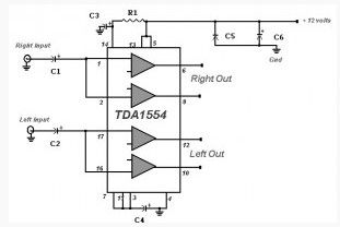
This is the basic circuit of the 22 Watt Stereo Amplifier with IC TDA 1554. This circuit can be used for audio home amplifier and car audio amplifiers. It is extremely simple design, inexpensive and very easy to build. Even a newbie hobbyst will easy assemble this circuit.
This circuit requires a 12V supply voltage that can be make your own or direct from your car battery.
(View)
View full Circuit Diagram | Comments | Reading(1395)
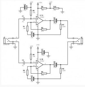
Balanced Input/Output Pre-amplifier Circuit
Published:2013/3/14 3:16:00 Author:Ecco | Keyword: Balanced Input, Output, Pre-amplifier
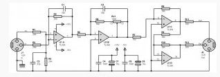
This Balanced pre amp circuit is designed to amplify a little line-level audio signal (from 0 dB to 20 dB), and has balanced inputs and outputs. The scheme uses only conventional components, you’ll have no trouble finding in any electronics retailer. For a stereo version, simply to make two copies.
Input stageThe input stage is focused on a four-op amp content in the TL084. It is mounted in a simple differential amplifier. It is true that this is not the best possible configuration, but it is much less critical than for a low stage level (preamp, for example) and give results, however, quite satisfactory.
(View)
View full Circuit Diagram | Comments | Reading(5100)
Low Power Amplifier 2 x 100 mW circuit
Published:2013/3/14 3:15:00 Author:Ecco | Keyword: Low Power Amplifier, 2 x 100 mW
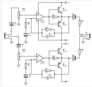
This Low Power Amplifier 2 x 100 mW, without great pretensions, is simple to assemble, and works with a single power supply 9V battery (for example). However, it works a little better with a supply voltage slightly higher, +12 V to +18 V.
The Low Power Amplifier 2 x 100 mW circuit is based on the combination of op amp and an output stage push-pull with two transistors to charge more than a few mA and assuring to have few mW required for comfortable listening.The voltage gain is about 10 (20 dB), and corresponds to the ratio of resistors R3 / R2 for the left channel and R7 / R6 to the right path.
(View)
View full Circuit Diagram | Comments | Reading(2090)
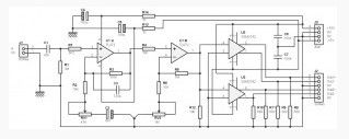
Asymmetric Pre-amplifier Circuit
Published:2013/3/14 3:13:00 Author:Ecco | Keyword: Asymmetric Pre-amplifier
This Asymmetric Pre amp circuit is designed to amplify a signal little AF stereo line-level, and has an unbalanced input and output. It is perfect to add that little something missing to attack a power amplifier in good condition For example, to slightly increase the output level of a portable player like “MP3″ or “FM tuner” supply power single or symmetrical (double), as desired.
(View)
View full Circuit Diagram | Comments | Reading(3096)
100mW Stereo Amplifier Circuit based TL082
Published:2013/3/14 3:03:00 Author:Ecco | Keyword: 100mW Stereo Amplifier
This 100mW stereo amplifier is designed to integrate with a mixer, or can be used independently or as a basis for a multi-box headphone amplifier (box 4 headphone amplifiers for example). It operates under a balanced power supply with a range from + / -9 V and + / -18 V.
The 100mW stereo amplifier based TL 082 circuit is based on the combination of op amp and an output stage (pseudo) two push-pull transistors, capable of delivering power to feed more than comfortable headphones, even if it at an average performance.Input of both left and right channels will be carried out through a stereo female jack if you want to embed this amp in a box reserved for this purpose. Of course, this jack will not be necessary if the integration is made with your own mixer.
(View)
View full Circuit Diagram | Comments | Reading(2187)
Low Cost Pre-amplifier Circuit based TL072
Published:2013/3/14 3:01:00 Author:Ecco | Keyword: Low Cost Pre-amplifier
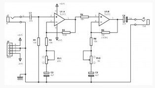
This simple pre amp based TL 072 circuit is certainly not the best, it doesn’t even have tone controls. But has the advantage of being simple to build and also have benefits from a very low cost.
The power supplyThe supply voltage must be a symmetrical, two batteries of 4.5 V or 9V battery is enough. You can also use a single supply of between 9 V and 24 V, associated with a symmetrizer power such as that seen in the following diagram:
(View)
View full Circuit Diagram | Comments | Reading(3205)
Guitar Pre-amp Circuit based TL072
Published:2013/3/14 3:00:00 Author:Ecco | Keyword: Guitar Pre-amp Circuit
This guitar pre amp circuit has a high input impedance unbalanced and two balanced outputs completely independent set to deal high capacitive loads, and can therefore be used with long cables.
The guitar pre amp assembly does not really particular comment. The use of a type TL072 integrated circuit for the input stage is explained by the fact that it has a high input impedance (FET input) which allows to set the input impedance of assembly to the desired value, by 1Mohm, R1. Amplification is carried out by two separate stages to ensure a better stability and bandwidth when the gain is at its maximum. The completion of the two balanced outputs is facilitated by the use of line driver circuits specialized for this purpose in classical SSM2142. You will notice the presence of 680 ohm resistors on each output of the SSM2142. It is possible to do without it, provided to connect the terminals 7 and 8 together, and the terminals 1 and 2 together.
(View)
View full Circuit Diagram | Comments | Reading(1872)
Headphone amplifier based OPA134PA
Published:2013/3/14 2:58:00 Author:Ecco | Keyword: Headphone amplifier
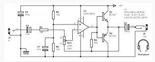
The Headphone amplifier circuit is based on a combination of the op amp and output stage with two transistors, capable of delivering power to feed the headphones comfortably.
(View)
View full Circuit Diagram | Comments | Reading(1403)
Guitar pre amplifier based TL071
Published:2013/3/14 2:57:00 Author:Ecco | Keyword: Guitar pre amplifier
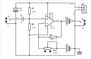
The Guitar preamp circuit is very simple, using only a single integrated circuit, a type TL071 OP AMP.
The title is an exaggeration, given that the gain of the circuit is intentionally low. When we talk about pre-amp, you can expect amplification often great … that is not the case here. The purpose of this Guitar preamp circuit is mainly to provide impedance matching to allow the use of long cables between a guitar and an amp, while limiting losses to the maximum audio. Although originally this circuit is provided with a gain setting, we will see that it is entirely possible to delete it.This TL071 integrated circuitcan be replacedeasilybyanLT1012,aTL061(which consumesalittle less than theTL071), or evenby a TL081. With the components shown in this circuit will get 110k ohm input impedance. If this value seems a little low, you can increase the value of the two resistors R1 and R2. Using two resistors 1MOhm, you will get the input impedance of about 500k ohm.
(View)
View full Circuit Diagram | Comments | Reading(5079)
2×50 mW Stereo Headphone amplifier
Published:2013/3/14 2:56:00 Author:Ecco | Keyword: 2×50 mW, Stereo Headphone amplifier
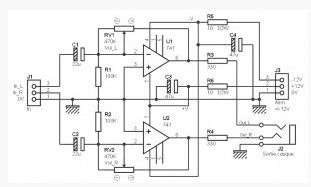
This headphone amplifier uses common components and probably will fill those looking for a really simple assembly. This is a typical Stereo Headphone amplifier example of what was found on the cheap small mixer, and even on some tables for mobile disco. The headset used can have impedance of 8 ohms and 200 ohms, this value is more appropriate here.
The Stereo Headphone amplifier schematic above you can see that simplicity is really up, since it shows all the components necessary for both left and right channels. Do not expect miracles from this type of assembly, the distortion can be quite important if you push too much volume … If you are looking for a headphone amp that sounds “loud and clear” for listening to your classical music pieces in your couch, I’m sorry, this circuit will probably not meet your expectations. But ‘normal’ use, it is a good small amp with extra nice.
(View)
View full Circuit Diagram | Comments | Reading(1410)
10 W Power amplifier based TDA2003
Published:2013/3/14 2:55:00 Author:Ecco | Keyword: 10 W Power amplifier
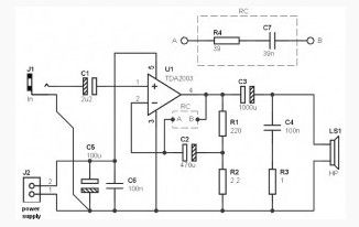
This 10 W Power amplifier, is simple to perform, and works with a single power source between 12 V and 18 V. It is based on the use of type TDA2003 integrated amplifier, capable of its own to deliver around 10 W power to the load of 2 ohms and the power supply voltage of 18 V, the distortion level of 10% (0.15% up to 7.5 W). With the use of two types of integrated circuits is in bridge mode, it is possible to quadruple the output power amplifier to 40 W (2 ohm load, with 18 V power supply and a distortion of 10% – 30 W max for the distortion of 0.15%).
The 10 W Power amplifier circuit diagram, based on the application note from SGS-Thomson, suggests the relative simplicity of this achievement. And that’s mainly what made the TDA2003 is popular (according to the TDA2002, a little less powerful but you can use here without changing anything else in the components).
(View)
View full Circuit Diagram | Comments | Reading(1689)
| Pages:149/2234 At 20141142143144145146147148149150151152153154155156157158159160Under 20 |
Circuit Categories
power supply circuit
Amplifier Circuit
Basic Circuit
LED and Light Circuit
Sensor Circuit
Signal Processing
Electrical Equipment Circuit
Control Circuit
Remote Control Circuit
A/D-D/A Converter Circuit
Audio Circuit
Measuring and Test Circuit
Communication Circuit
Computer-Related Circuit
555 Circuit
Automotive Circuit
Repairing Circuit