
Circuit Diagram
Index 148
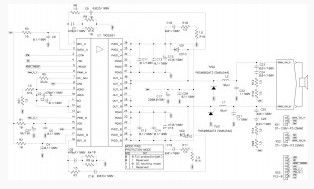
144MHz Power Amplifier Circuit
Published:2013/3/18 1:02:00 Author:Ecco | Keyword: 144MHz , Power Amplifier
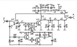
The 144 MHz Power amplifier is designed to work with the transceiver 2-meter band. Power output depends on the output transistor: KT 904 – 4 to 5 watts, KT 907 – 7 to 8 watts, 2N3375 – from 7 to 10 watts, 2N3632 – from 8 to 12 watts.
The transition from reception to transmission by VOX-switch, made by transistors VT2/VT3 (KT315). Kodensator Cl – 0,5-2,2 pF, establishes a reliable operation of the relay Kl.
Inductors L6 – L8 made wire of 0.4 mm, L6/L7 -6 turns, L8 – 100 turns. High-frequency coil wound around a silver-plated wire of 0.8 mm: Ll – 2 turns, the frame – 8 mm, the winding length of 11 mm; L2/L3 – 4 turns, the frame – 6.8 mm, the winding length of 10 mm; L4/L5 – 5 turns, the frame – 5.2 mm, the winding length of 12 mm.Output impedance 75 ohms cascade. Capacitor C4 provides from 33 to 180 pF.
(View)
View full Circuit Diagram | Comments | Reading(2934)
Easy 100 Watt Power Amplifier
Published:2013/3/18 1:01:00 Author:Ecco | Keyword: 100 Watt, Power Amplifier
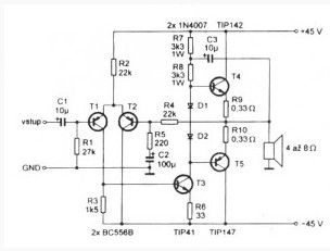
Through the use of powerful constituents (Darlington) transistor T4, T5, final stage managed to produce a sufficiently powerful amplifier of the five transistors, and three of them are shallow.
The output stage operates in B, the displacement at the bases of transistors is defined by two diodes D1, D2, which excludes the building process. The input stage, the differential pair supports a “zero” level “to break” and closes the negative feedback circuit of AC.
When you build should pay special attention to placement of elements on the board and the amplifier power supply to eliminate self-excitation of the amplifier, which can damage the output transistors connected to an amplifier and acoustic systems.
(View)
View full Circuit Diagram | Comments | Reading(5310)
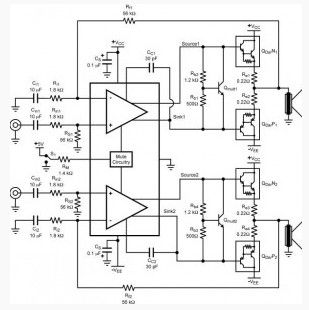
High Quality Audio Amplifier for Computer
Published:2013/3/18 1:00:00 Author:Ecco | Keyword: High Quality, Audio Amplifier, Computer
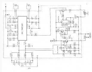
Using a modern element base import, is not difficult to self-assemble high-quality audio amplifier. It will take only one chip firms TOSHIBA. You do not need adjustment, which implies the presence of costly instrumentation.
The electrical circuit of the amplifier is shown in Fig. 1. For its production is chosen in a typical IC TA8205AN inclusion. Usually it is applied to a Hi-Fi class due to low harmonic distortion. Suitable as a similar but more powerful: TA8210AN TA8215AN and (wiring diagram in this case does not change).
Unlike many other types, except for low harmonic distortion in the chip provides for work in standby mode, ie with low power consumption from the power supply in case the input DA1 / 4 zero. In addition, the amplifier provides a soft inclusion, eliminating the clicks in the speakers when power is applied.
(View)
View full Circuit Diagram | Comments | Reading(1403)
25 Watt Power Amplifier based MosFet
Published:2013/3/15 4:30:00 Author:Ecco | Keyword: 25 Watt, Power Amplifier, MosFet
25 Watt power amplifier based MosFet, can be connected directly to the signal source and does not require pre-amplifier to drive. The amplitude of the input signal must reach the level of 200 mV. This signal is normally present on the linear output recorder, CD player, computer sound card and other devices. To adjust the volume can be placed at the entrance to the potentiometer 10 kohm. Trimmer adjustable quiescent current. It must be within 100 mA.
(View)
View full Circuit Diagram | Comments | Reading(3167)
50 Watt Audio Amplifier based L8063
Published:2013/3/15 4:29:00 Author:Ecco | Keyword: 50 Watt, Audio Amplifier
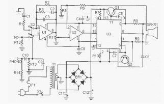
This 50 watt audio amplifier based L8063 circuit diagram is simple and easy to build. Input can be from radio, TV or your mp3 player device. This circuit has a phono input for a record player, guitar, microphone or other un-amplified source. This circuit can also be for a subwoofer amplifier, of course, by adding an active crossover circuit subwoover before input.
(View)
View full Circuit Diagram | Comments | Reading(1362)
Power Amplifier 2x18W with TDA1516Q
Published:2013/3/15 4:26:00 Author:Ecco | Keyword: Power Amplifier, 2x18W
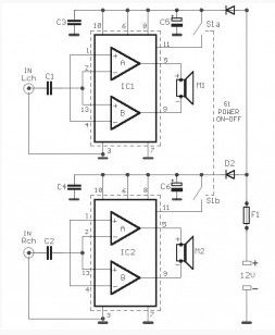
In many cars, cassette players use amplifiers that power does not exceed 5W with enough distortion to the limits of power. The problem is solved with the use of external amplifiers will have the opportunity to earn much more power with much less distortion. Given the voltage of the car is +12 V, we have the opportunity to take power over a threshold. The solution is to use two amplifiers in bridge connection, so the output quadrupled, at least theoretically, and at best, doubled.
A complete set will be much easier to implement the above, easily and with very few external components, is the TDA1516Q, which contains two amplifiers in a shell, with a profit of 20dB, with protection against overheating and short circuiting. In connection bridge as in the circuit, we can output 18W at 4 Ohm load, with 0.5% distortion and power over 20W by deformation close to 10%, power good for the car. The drive amplifiers can be accessed from the output of existing amplifiers. You may need to engage in a series potesometro, which will adjust the level to a level so as not to have distortion from overdriving. This circuit can be used for purposes other car, driving a small computer speakers. The amplifiers should be placed on a good heatsink.
(View)
View full Circuit Diagram | Comments | Reading(1545)
Class D Amplifier for ATtiny15L
Published:2013/3/15 4:25:00 Author:Ecco | Keyword: Class D , Amplifier , ATtiny15L
Recently, the widespread use of amplifiers have high efficiency – 90% or more. The sound signal is converted into a PWM (pulse width modulated), which explains their high efficiency, since the output stage while working in a key mode. Modern designs of such amplifiers – a monolithic chip, integrate processor and powerful output stages. Experiment with them, for example, to change the PWM conversion algorithm is difficult.
These units can get acquainted with one embodiment of the amplifier is Class D. Controller ATtiny15L AVR family firm Atmel is perfectly suited for this purpose, because it contains a ten-digit analog-digital converter (ADC) and a timer with a pulse-width modulator (PWM).
(View)
View full Circuit Diagram | Comments | Reading(2298)
Audio Frequency Amplifier 20W based LM1875
Published:2013/3/15 4:24:00 Author:Ecco | Keyword: Audio Frequency Amplifier, 20W
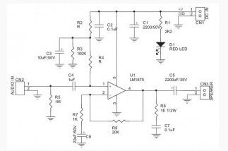
This scheme requires a minimum number of components. The amplifier has a good performance and very low harmonic distortion. At the main component of the amplifier is chip LM1875 company National Semiconductor , which has protected against short circuit and overheating.
(View)
View full Circuit Diagram | Comments | Reading(1156)
Preamplifier for ECM Microphone
Published:2013/3/15 4:22:00 Author:Ecco | Keyword: Preamplifier , ECM Microphone
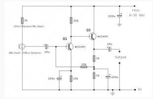
A microphone amplifier that may be used with either Electret Condenser Microphone (ECM) inserts or dynamic inserts, made with discrete components.
Both transistors should be low noise types. In the original circuit, is used BC650C which is an ultra low noise device. These transistors are now hard to find but BC549C or BC109C are a good replacement. The circuit is self stabilizing and will set its quiescent point at roughly half the supply voltage at the emitter of Q2. This allows maximum output voltage swing and also the highest dynamic range.
The electret condenser microphone (ECM) contains a very sensitive microphone element and an internal FET preamp, a power supply in the range 2 to 10 volts DC is therefore necessary. Suitable ECM’s may be obtained from Maplin Electronics. Although the schematic is drawn showing a three terminal ECM, two terminal ECM’s may be used, the following page in the practical section shows the changes.
(View)
View full Circuit Diagram | Comments | Reading(1671)
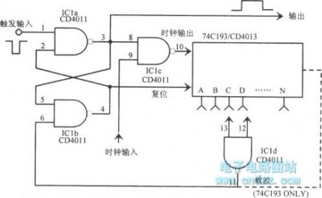
Amplifier Auto off Timer Circuit
Published:2013/3/15 4:20:00 Author:Ecco | Keyword: Amplifier, Auto off, Timer
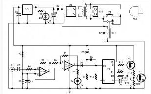
This circuit turns off the power, or any other device when the input signal is absent for more than 15 minutes.
Pressing the P1 circuit is switched on and supplies power to any device connected to the outlet SK1. The input signal is amplified and limited by IC2A and IC2B, and controlled light-emitting diode D4. In the flash of the LED D4, even very short, chip IC3 is reset and restarts its counting. At the conclusion 2 IC3 remains low, the transistors are opened and the relay is on. If within 15 minutes of input was not, ends up by chip IC3, and the output 2 is set high. Q1 and Q2 are closed, and relay switches off. Accordingly, the device connected to SK1, are disconnected from the network. The chain of C5 and R9 is used to reset the counter IC3 initial power-on. P2 button at any time to disable the device manually.
(View)
View full Circuit Diagram | Comments | Reading(1820)
Inverting Amplifier Uses Two Class AB Amplification Isolated Cells
Published:2013/3/15 4:19:00 Author:Ecco | Keyword: Inverting Amplifier , Two Class, AB Amplification , Isolated Cells
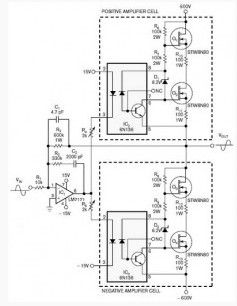
Transistors are used often as the three lead-amplifying devices, in which the voltage input and output signals are measured from the total output. Thus, the input and output tied to the voltage on this pin. On the other hand, the four pin power allows you to unleash the input and output circuits. Using optical isolation, you can create a four-pin power class AB. Since the magnitude of the output voltage optocoupler limits its use, you can use discrete transistors for the isolated amplifier.
On figure 1 is a simple, inverting amplifier with class AB output signal amplitude value 1 kV, which uses two identical amplifying cells. Frequency response amplifier gain full located in the region from DC to 20 kHz.
You can provide gain and higher frequencies, but at a lower value of gain. Ratio of resistors R1 and R2 set the gain. This scheme eliminates the need for multiple components to the level shifts, which are commonly used in standard construction of the scheme. Positive and negative cells gain controlled in opposite phase.
(View)
View full Circuit Diagram | Comments | Reading(1601)
Compact Power Amplifier based LM386
Published:2013/3/15 4:18:00 Author:Ecco | Keyword: Compact Power Amplifier
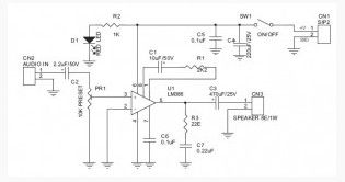

The compact power amplifier chip LM386 is perfect if the whole scheme powered from the battery.This circuit can be used as an amplifier for portable speakers because of its small and compact.
(View)
View full Circuit Diagram | Comments | Reading(1325)
315 Watt Class D Power Amplifier
Published:2013/3/15 4:17:00 Author:Ecco | Keyword: 315 Watt, Class D , Power Amplifier
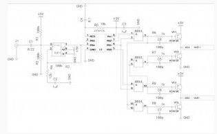
This audio amplifier based TAS5261 (bridge digital amplifier) has output power of 315 watts per channel and an efficiency up to 96% is suitable for use in a variety of Sound applications, such as home theater systems.
Reducing the cost and availability of high-bit ADC and digital signal processors have contributed to the emergence of high power amplifiers, D-class, based on pulse-width modulation. Work output transistor stages in a key mode of such amplifiers allows a few, sometimes dozens of times to increase efficiency, thereby reducing heat generation amplifier, its size and cost. Among all the audio amplifier device class D are the most cost-effective, thanks to the use of digital signal processing. It eliminates the possibility of distortion and noise in the pre-amplifier paths, streamlines and simplifies all kinds of linear and nonlinear signal conversion without using mechanical adjustment components, extends the functionality.
(View)
View full Circuit Diagram | Comments | Reading(1952)
High Precision Audio Frequency Amplifier based LM4702
Published:2013/3/15 4:15:00 Author:Ecco | Keyword: High Precision, Audio Frequency Amplifier
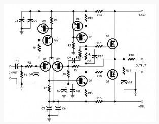
New chip LM4702 from National Semiconductor allows you to create audio-frequency amplifiers (AF) with a nominal output power of 300 W and low noise. A characteristic feature of this chip is a high level voltage, which allows high power output when using external transistors.Practice shows that the use of power amplifier circuits AF (audio frequency) performed on a single chip, the main factor in choosing components for reproducing parts of the developed device are easy to set up and a small number of elements binding. However, in most cases the quality of the sound signal does not fall under the class HI-FI in connection with a high percentage of non-linear distortion.
This fact is associated not only with engineering solutions such chips, but the fact that the temperature of the elements of input and output stages are directly dependent on each other.
(View)
View full Circuit Diagram | Comments | Reading(2195)
Simple 150 Watt Amplifier with Darlington Transistor
Published:2013/3/15 4:14:00 Author:Ecco | Keyword: 150 Watt, Amplifier , Darlington Transistor
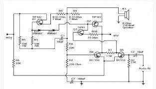
TIP147 and TIP142 – Darlington complementary pair of transistors that are popular because of their indestructibility. The transistors are designed for operating current of 5 amps and the collector voltage of 100 V. The two transistors BC558 (Q4 and Q5) made pre-amplifier bias adjustment for Q1, Q2, Q3 (TIP142, TIP147, TIP42 ). This 150-Watt Amplifier scheme is very reliable that can assemble on any breadboard. To power the circuit requires bipolar power supply ± 45 V and capable of giving a current of 5 A.
(View)
View full Circuit Diagram | Comments | Reading(2526)
Power Amplifier Basic (Part 1)
Published:2013/3/15 4:13:00 Author:Ecco | Keyword: Power Amplifier
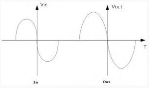
My previous post was mostly about schemes amplifier circuit without knowing what it is an power amplifier. In this post will be discussed on the the Power amplifier basic, what is inside and how they work.What is a Power Amplifier – on, for brevity, usually called “PA”. In general, the Power amplifier block diagram is divided into three parts:
The input stage
Intermediate stage
The output stage
These three sections do one task – to increase power output to levels that can drive the load with low impedance – the dynamic head or headphones. How do they do? It’s easy – PA requires direct current power supply and converts it to AC, but keep the shape of the output signal follows the shape of the input signal.
But, unfortunately, all that is good only in theory. In practice, audio design, we use a non-ideal resistors, capacitors and transistors, in particular. Therefore, the output can be very different form of input seriously, and this problem is called distortion.
(View)
View full Circuit Diagram | Comments | Reading(1157)
Car Amplifier Circuit 2x40W based TDA8560Q
Published:2013/3/15 4:11:00 Author:Ecco | Keyword: Car Amplifier , 2x40W
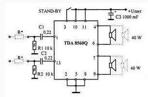
TDA8560, being a complete analogue of the well-known chip TDA1557Q, in fact – its a whole new amp. This car amplifier circuit gives an output power 40 watts per channel at 2 ohm load, and 22 Watts on 4 ohms load. Perhaps you are wondering how to get 40 watts of power? And answer is : you can find 2 ohm speakers (if any), or you can connect an amplifier with a pair of 4 ohm speakers in parallel in order to get 2 ohm load
It is obvious that this feature is the ability TDA8560-operate on two pairs of 4 * Ohm speaker can announce one-chip whole interior of the car – a pair of speakers in the doors, a couple on the back of a shelf – and all this with the total capacity – 80 W!
(View)
View full Circuit Diagram | Comments | Reading(4437)
2x4W Stereo Tube Amplifier Circuit
Published:2013/3/15 4:10:00 Author:Ecco | Keyword: 2x4W, Stereo Tube Amplifier
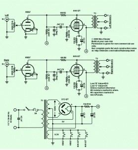
Here the schematic diagram of 2x4W stereo tube amplifier which built based 5 power tubes component. This amplifier will produces up to 4 watt audio power for each output channel.
(View)
View full Circuit Diagram | Comments | Reading(1839)
Pulse triggering monostable circuit
Published:2013/3/14 1:49:00 Author:Ecco | Keyword: Pulse triggering, monostable
Pulse triggering monostable circuit is shown as figure.
(View)
View full Circuit Diagram | Comments | Reading(763)
1Hz ~ 1MHz multivibrator circuit
Published:2013/3/15 2:57:00 Author:Ecco | Keyword: 1Hz ~ 1MHz , multivibrator
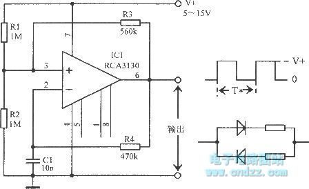
1Hz ~ 1MHz multivibrator circuit is shown as figure.
(View)
View full Circuit Diagram | Comments | Reading(1408)
| Pages:148/2234 At 20141142143144145146147148149150151152153154155156157158159160Under 20 |
Circuit Categories
power supply circuit
Amplifier Circuit
Basic Circuit
LED and Light Circuit
Sensor Circuit
Signal Processing
Electrical Equipment Circuit
Control Circuit
Remote Control Circuit
A/D-D/A Converter Circuit
Audio Circuit
Measuring and Test Circuit
Communication Circuit
Computer-Related Circuit
555 Circuit
Automotive Circuit
Repairing Circuit