
Circuit Diagram
Index 158
Expanded Scale Battery Volt Meter
Published:2013/3/6 3:21:00 Author:Ecco | Keyword: Expanded, Scale Battery, Volt Meter
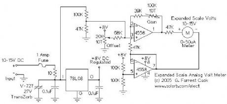
This circuit is used to measure the voltage on a 12V (nominal) lead acid rechargeable battery system. It was specifically designed for use in solar powered systems, but is general enough that it can be used for automotive or other 12V systems. Lead acid batteries normally spend their working lifetime in the voltage range of 11-15 Volts. This meter circuit was designed to show the voltage range of 10-15V on an analog meter movement, it can be used to show the battery charge state from empty to full.
(View)
View full Circuit Diagram | Comments | Reading(1099)
WGR1 - 12 Volt Wind Generator Regulator
Published:2013/3/6 3:20:00 Author:Ecco | Keyword: 12 Volt, Wind Generator, Regulator
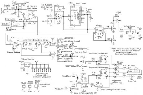
The WGR1 circuit is used to regulate the charging of a lead acid battery system from a DC-output wind generator. It consumes minimal power when idle and efficiently delivers charging power to the battery when the wind generator is up to speed. Excess charging power is diverted to a large dump resistor, the heat produced can be used to keep the battery warm when used in cold climates. The WGR1 circuit is designed to operate in conjuntion with a photovoltaic (solar) charge controller such as my SCC3 design.
The WGR1 circuit features make-before-break switching. This ensures that the current from the wind generator is either going to the battery, to the load, or very briefly to both during switching times. By managing the switching this way, high voltage transients are minimized, protecting the MOSFET transistors. The make-before-break switching also guarantees that there will always be a load on the wind generator. Unloaded wind generators tend to spin out of control and may even self-destruct.
This project came about after my 400W Southwest Windpower air-X wind generator was exposed to winds in excess of 120Mph (above the unit's maximum rated wind speed), causing the internal control electronics to burn out. The air-X internal regulator was replaced with a set of six high-current diodes wired in a standard 3-phase bridge rectifier configuration. The resulting pulsating DC voltage is fed to this circuit via some heavy-duty wiring. (View)
View full Circuit Diagram | Comments | Reading(3521)
SPC2 6 Amp Solar Power Center
Published:2013/3/6 3:16:00 Author:Ecco | Keyword: 6 Amp, Solar Power Center
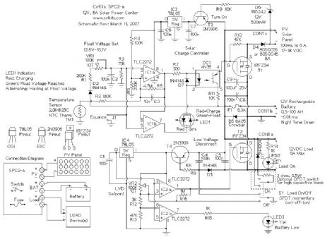
The SPC2 is a solar power center, it can be used to handle all of the power functions for small 12 Volt solar powered devices. It contains a photovoltaic charge controller and a low voltage load disconnect circuit. The low voltage disconnect has a load on-off switch, and a battery low voltage indicator. By using the SPC2 as the center of a solar powered device, long battery life is assured. The SPC2 is primarily designed to be a solar lighting controller, it can be used to power radios and other high capacitance loads with a minor switch and circuit modification (shown in dotted lines on the schematic). (View)
View full Circuit Diagram | Comments | Reading(4402)
Solar Panel Charge Controller / Low Voltage Disconnect Circuit (SPC1)
Published:2013/3/6 3:14:00 Author:Ecco | Keyword: Solar Panel, Charge Controller , Low Voltage Disconnect

This Solar Power Center design appeared as a pair of articles in Home Power Magazine.
The charge controller is used to connect a solar panel to a 12 volt lead acid battery, it regulates the charging of the battery and allows the battery to be charged up to a preset voltage. This prevents the battery from over-charging and boiling off electrolyte.
The low voltage disconnect is used to connect a load to the same 12 volt lead acid battery, the LVD acts as a smart switch, it auto disconnects the load if the battery voltage falls below a set point.
When used together, these circuits keep the battery operating within normal voltage limits which greatly extends the life of the battery. The circuit board was designed to be split into two independent circuits, that is why there are two connections to the battery.
(View)
View full Circuit Diagram | Comments | Reading(6142)
SCC2 10 Amp Solar Charge Controller
Published:2013/3/6 3:13:00 Author:Ecco | Keyword: 10 Amp , Solar Charge Controller
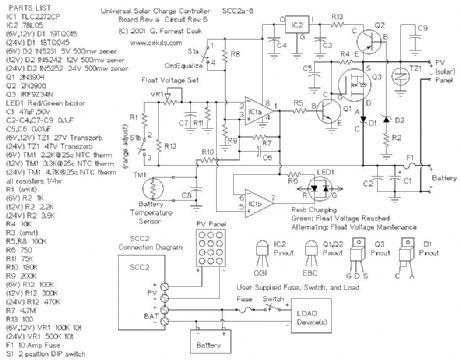
The SCC2 is a solar charge controller, its function is to regulate the power flowing from a photovoltaic panel into a rechargeable battery. It features easy setup with one potentiometer for the float voltage adjustment, an equalize function for periodic overcharging, and automatic temperature compensation for better charging over a range of temperatures.
The goal of the circuit design was to make a charge controller with analog simplicity, high efficiency, and reliability. A medium power solar system can be built with a 12V solar panel up to 10 amps, the SCC2, and a rechargeable battery. The SCC2 works with lead acid, NiCD and NiMH batteries with ratings from less than one to several hundred amp-hours. With the appropriate parts selection, the SCC2 can be operated at 6V, 12V, 24V or other voltages.
(View)
View full Circuit Diagram | Comments | Reading(4499)
Analog Shunt-mode 12V 500mA Solar Charge Controller
Published:2013/3/6 3:11:00 Author:Ecco | Keyword: Analog, Shunt-mode , 12V, 500mA, Solar Charge Controller
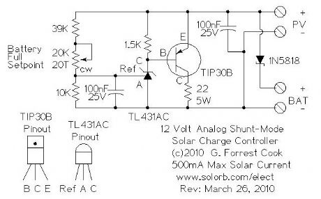
This circuit is an analog alternative to the switching Shunt-mode Solar/Wind Charge Controller. It is one of the simplest ways to regulate the solar charging of a rechargeable battery, using about a dozen parts. Despite its simplicity, the circuit is relatively efficient. Unlike the all-or-nothing switching shunt-mode controller, this circuit gradually diverts solar power from the battery to the dump load resistor as the battery reaches the preset battery float voltage. As shown, the circuit is limited to 500mA of solar charging current. Higher power systems will be better served with a series switching charge controller.
The circuit shown is set up to charge a 12V battery, it can be modified to support both lower and higher voltage battery systems by changing the value of the 39K resistor.
(View)
View full Circuit Diagram | Comments | Reading(4144)
Shunt-mode Solar/Wind Charge Controller
Published:2013/3/6 3:10:00 Author:Ecco | Keyword: Shunt-mode , Solar, Wind , Charge Controller
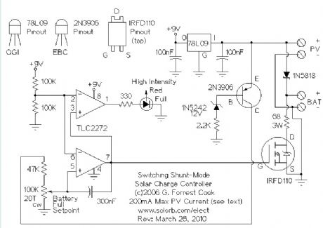
When connecting a solar panel to a rechargeable battery, it is important to use a charge controller circuit to prevent the battery from overcharging. Charge control can be performed with a number of different circuit types. Low-power solar systems can use a series analog charge controller (voltage regulator), an example is shown as the upper part of this circuit. Higher power systems can use a series switching charge controller, such as my SCC3 design. Very large systems, such as grid-tied installations, often use a maximum power-point (MPPT) charge controller. This shunt-mode circuit is best suited for low-power systems, it is more efficient than charge controllers based on series-mode voltage regulators.
Series regulators (both analog and switching) control battery charging by interrupting the flow of current from the solar panel to the battery when the battery reaches a preset full voltage. MPPT controllers use controllable switching regulator circuits to convert PV power to high voltage and back down to lower voltages, they are complicated and require a bit of power to operate, but offer excellent efficiency on high power systems.
This circuit is for a switching shunt-mode charge controller. In a shunt-mode circuit, the solar panel is connected directly to the battery via a series diode. The diode prevents battery current from flowing back through the PV panel at night. When the solar panel charges the battery up to the desired full voltage, the shunt circuit connects a resistive load across the battery in order to absorb the excess PV charging current. An alternate but similar approach to this switching shunt-mode PV regulator is the Analog Shunt-Mode circuit.
(View)
View full Circuit Diagram | Comments | Reading(7703)
60 Amp Modification for the SCC3 12 Volt Solar Charge Controller
Published:2013/3/6 3:08:00 Author:Ecco | Keyword: 60 Amp, Modification , 12 Volt, Solar Charge Controller
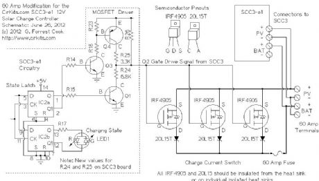
This article describes modifications that can be made to the 12V, 20 Amp SCC3 solar charge controller to allow operation at up to 60 Amps. Similar modifications can be performed to achieve a maximum operating current of 40 Amps (2 sets of IRF4905 MOSFETs and 20L15T diodes) or 80 Amps (4 sets of IRF4905 MOSFETs and 20L15T diodes). This article describes the modification for 60 Amps.
(View)
View full Circuit Diagram | Comments | Reading(6102)
BVM1 - 12 Volt Battery Voltage Monitor
Published:2013/3/6 2:56:00 Author:Ecco | Keyword: 12 Volt, Battery Voltage Monitor
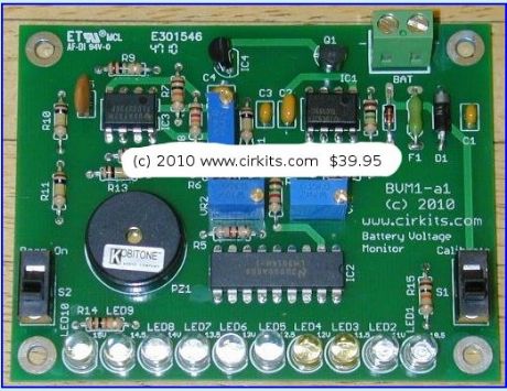
The BVM1 is an ultra low power ten LED battery voltmeter circuit that is optimized for monitoring solar-charged 12V battery systems. The circuit features an expanded meter scale that displays ten color-coded voltage steps from 10.5V to 15.0V. Power is conserved by only turning on the appropriate LED for a short but bright flash once every 1.25 seconds. The LED display can be turned on continuously (no blinking) by turning the Calibrate switch on, more battery power is consumed in this mode.
The BVM1 also includes a battery low voltage beeper that warns when the battery voltage drops below a preset voltage. The beeper can be turned on and off with the L.V. Beep Activate switch.
The BVM1 is protected against reverse voltage connection and is fused for safety. (View)
View full Circuit Diagram | Comments | Reading(1994)
LVD1 Circuit Extensions
Published:2013/3/6 2:54:00 Author:Ecco | Keyword: Extensions
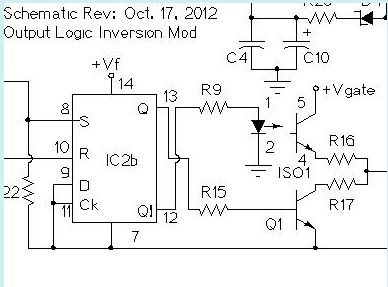
It is easy to invert the logic of the LVD1 output circuit, this can be useful if you want to automatically activate an AC-operated battery charger or a backup generator when your battery gets low. The above circuit shows the modification to the LVD1 schematic for inverting the output logic. The LVD1 load connection can drive an AC-output solid state relay to switch on power to a backup AC-operated charger, a DC-output solid state relay can be used to control a generator starter circuit.
The AC charger should be tested to see if its DC output connection consumes reverse current from the system battery when the charger is off. If this occurs, a suitably rated Schottky diode should be put between the AC charger's output terminals and the battery to prevent the reverse current from discharging the battery.
(View)
View full Circuit Diagram | Comments | Reading(779)
LVD1 - 12 Volt 15 Amp Low Voltage Disconnect
Published:2013/3/6 2:53:00 Author:Ecco | Keyword: 12 Volt, 15 Amp , Low Voltage Disconnect
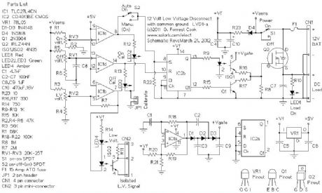
This circuit provides a low voltage disconnect (LVD) function for battery operated 12 Volt DC power systems. It is ideal for use with solar powered battery systems. The LVD1 circuit is designed to protect a battery from excessive discharge. Rechargeable batteries will have a much longer life if they are never allowed to discharge below the manufacturer's recommended minimum voltage.
The LVD1 circuit supports common-ground loads by switching the high side of the load on and off. The LVD1 circuit is protected against reverse battery connection. This circuit is designed to be used in conjunction with the SCC3 solar charge controller, LVD1 and SCC3 kits are available from CirKits.
The circuit features both Automatic and Manual modes of operation. The controls include an On-Off power switch and an On-Off-(On) switch for selecting the Auto-on and (Manual-on) modes of operation. An isolated low voltage detect signal is provided by the circuit, this can be monitored by a computer for a controlled shutdown prior to the disconnection of power. (View)
View full Circuit Diagram | Comments | Reading(2302)
SPC3 9 Amp in / 10 Amp out Solar Power Center
Published:2013/3/6 2:49:00 Author:Ecco | Keyword: 9 Amp , 10 Amp, out, Solar Power Center
The SPC3 is a solar power center, it can handle all of the power functions for a solar charged 12 Volt DC system. The SPC3 contains a 9 amp photovoltaic charge controller, a 10 amp low voltage load disconnect circuit and a pair of built-in white LEDs for area illumination. The low voltage disconnect circuit has a load on-off switch, and a battery low voltage indicator. By using the SPC3 as the center of a solar powered device, long battery life is assured. The SPC3 can be used for a self-contained solar lighting system, it can be used for making solar powered audio and radio devices and much more.
(View)
View full Circuit Diagram | Comments | Reading(1915)
SCC3 - 12 Volt 20 Amp Solar Charge Controller
Published:2013/3/6 2:47:00 Author:Ecco | Keyword: 12 Volt , 20 Amp, Solar Charge Controller
The SCC3 is a solar charge controller, its function is to regulate the power flowing from a photovoltaic panel into a rechargeable battery. It features easy setup with one potentiometer for the float voltage adjustment and an equalize function for periodic overcharging. Automatic temperature compensation optimizes battery charging over a wide range of temperatures. The SCC3 is able to handle reverse polarity connection of both the battery and photovoltaic panel.
The design goals of this circuit were efficiency, simplicity, reliability and the use of field replaceable parts. The circuit has been designed to be radio-quiet, which makes it suitable for ham radio applications. A medium power solar system can be built with the SCC3, a 12V (nominal) solar panel that is rated up to 20 amps, and a lead acid or other rechargeable battery that is rated from 500 milliamp hours to 400 amp hours of capacity.
(View)
View full Circuit Diagram | Comments | Reading(1492)
VOLTAGE DOUBLER Circuit
Published:2013/3/5 21:07:00 Author:Ecco | Keyword: VOLTAGE DOUBLER
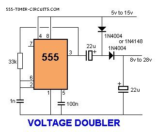
A voltage higher than the supply can be created by a Charge-Pump circuit created with a 555, diodes and capacitors as shown in the following circuit. The output will deliver about 50mA.
(View)
View full Circuit Diagram | Comments | Reading(1408)
ZENER DIODE TESTER Circuit
Published:2013/3/5 21:05:00 Author:Ecco | Keyword: ZENER DIODE, TESTER
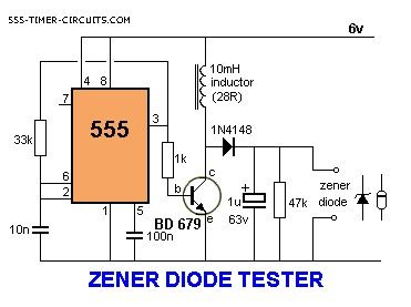
This circuit will test zener diodes up to 56v. See Talking Electronics website, left index, 200 Transistor Circuits (circuits 1-100) and go to Zener Diode (making) to see how to make a zener diode and how to create a zener voltage from a combination of zeners. Place the zener across the terminals in the circuit below and read the value across it with a multimeter set to 50v range.
(View)
View full Circuit Diagram | Comments | Reading(3745)
WAILING SIREN Circuit
Published:2013/3/5 21:03:00 Author:Ecco | Keyword: WAILING SIREN
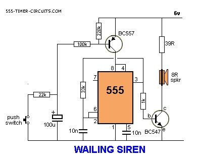
By pressing the button, the wailing sound increases. Releasing the button decreases the wailing. The circuit automatically turns off after about 30 seconds.
(View)
View full Circuit Diagram | Comments | Reading(1483)
UNEVEN CLICKS Circuit
Published:2013/3/5 21:02:00 Author:Ecco | Keyword: UNEVEN CLICKS
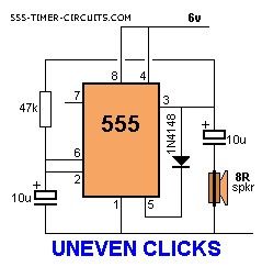
This circuit produces two clicks then a short space before two more clicks etc. Changing the voltage on pin, 5 via the diode, adjusts the timing of the chip.
(View)
View full Circuit Diagram | Comments | Reading(681)
TV REMOTE CONTROL JAMMER Circuit
Published:2013/3/5 21:00:00 Author:Ecco | Keyword: TV , REMOTE CONTROL , JAMMER
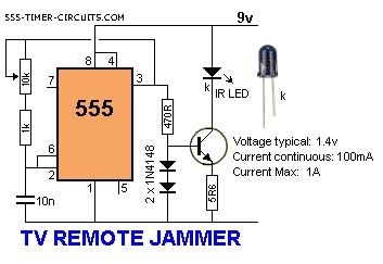
This circuit confuses the infra-red receiver in a TV. It produces a constant signal that interferes with the signal from a remote control and prevents the TV detecting a channel-change or any other command. This allows you to watch your own program without anyone changing the channel !! The circuit is adjusted to produce a 38kHz signal. The IR diode is called an Infra-red transmitting Diode or IR emitter diode to distinguish it from a receiving diode, called an IR receiver or IR receiving diode. (A Photo diode is a receiving diode). There are so many IR emitters that we cannot put a generic number on the circuit to represent the type of diode. Some types include: CY85G, LD271, CQY37N (45?, INF3850, INF3880, INF3940 (30?. The current through the IR LED is limited to 100mA by the inclusion of the two 1N4148 diodes, as these form a constant-current arrangement when combined with the transistor and 5R6 resistor.
(View)
View full Circuit Diagram | Comments | Reading(1351)
4 WAY TRAFFIC LIGHTS Circuit
Published:2013/3/5 20:58:00 Author:Ecco | Keyword: 4 WAY, TRAFFIC LIGHTS

This circuit produces traffic lights for a 4-way intersection. The seemingly complex wiring to illuminate the lights is shown to be very simple, in this diagram.
(View)
View full Circuit Diagram | Comments | Reading(7064)
TOY ORGAN Circuit
Published:2013/3/5 20:56:00 Author:Ecco | Keyword: TOY ORGAN
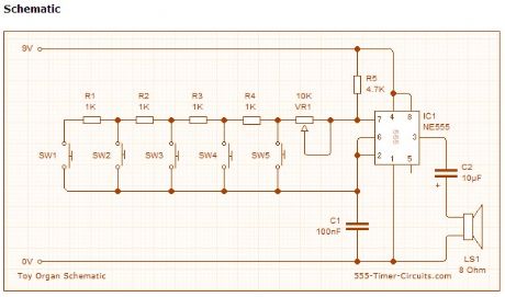
A circuit that produces 5 different sounds. Overview This circuit produces a tone according to the button being pressed. Only 1 button can be pressed at a time, that's why it is called a monophonic organ. You can change the 1k resistors to produce a more-accurate scale.
(View)
View full Circuit Diagram | Comments | Reading(1401)
| Pages:158/2234 At 20141142143144145146147148149150151152153154155156157158159160Under 20 |
Circuit Categories
power supply circuit
Amplifier Circuit
Basic Circuit
LED and Light Circuit
Sensor Circuit
Signal Processing
Electrical Equipment Circuit
Control Circuit
Remote Control Circuit
A/D-D/A Converter Circuit
Audio Circuit
Measuring and Test Circuit
Communication Circuit
Computer-Related Circuit
555 Circuit
Automotive Circuit
Repairing Circuit