
Circuit Diagram
Index 150
Active FM Amplifier
Published:2013/3/14 2:53:00 Author:Ecco | Keyword: Active FM Amplifier
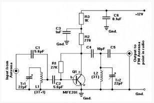
This Active FM Amplifier circuit is reliable, and it only requires a few components. This circuit works with only one active component of the UHF / VHF transistor type, MFE201.
This amplifier will pull in all distant FM stations clearly. Active FM amplifier circuit is configured as a common-emitter tuned RF pre-amplifier wired around the VHF / UHF transistor MFE201. There are several other types of transistors that will probably work as well, such as NTE107, 2SC2570, etc. but this is untested.
Adjust capacitor trimmers C1 and C2 for maximum gain. Input coil L1 is made up of 4 turns of 20SWG enamelled copper wire over the 5mm diameter former. It is tapped at the first turn from ground lead side. Coil L2 is just like L1, but has only 3 turns. Pin configuration is shown in the diagram.
(View)
View full Circuit Diagram | Comments | Reading(1557)
Active Antenna for AM/FM/SW
Published:2013/3/14 2:52:00 Author:Ecco | Keyword: Active Antenna , AM, FM, SW
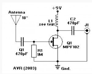
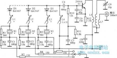
This simple AM/FM/SW Active Antenna circuit are able to be used for AM, FM, and Shortwave(SW). For the shortwave band, this kind of active antenna is comparable to a 20 to 30 ft wire antenna. It’s in addition designed to be used on receivers which use untuned wire antennas, for example cheap models and car radios.
L1 can be chosen for the application. A 470µH coil works on lower frequencies and lie in Am, for shortwave try a 20µH coil. This AM/FM/SW Active Antenna circuit can be powered by a 9 volt battery pack. If a power supply is used, bypass the power supply using a 0.04µF capacitor to prevent noise pickup. The antenna used on this circuit is a standard 18-inch telescoping type, but a thick piece of copper, bus-bar, or piano wire will also work fine.
(View)
View full Circuit Diagram | Comments | Reading(7319)
Variable Gain Amplifier controlled by voltage
Published:2013/3/14 2:51:00 Author:Ecco | Keyword: Variable Gain Amplifier , voltage
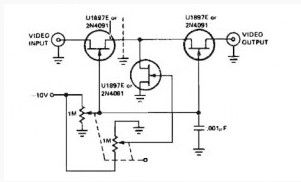
This is Variable Gain Amplifier controlled by voltage circuit function as video amplifier, it use 3 Field Effect Transistor (FET) type U1897E. U1897E FET can also be replaced with a 2N4091.
The tee attenuator provides for optimum dynamic linear range attenuation up to 100 dB, even at frequency = 10.7 MHz with proper layout.
(View)
View full Circuit Diagram | Comments | Reading(1468)
Power Booster based NE5535
Published:2013/3/14 2:50:00 Author:Ecco | Keyword: Power Booster
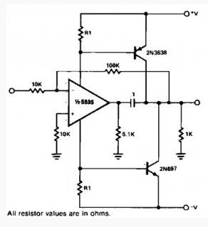
This is the schematic diagram of power booster circuit is capable of driving medium loads. The circuit as presented works with a NE5535 chip.
Other amps might be replaced only if R1 values are changed due to the Icc current needed by the amplifier. R1 needs to be calculated with the following expression
(View)
View full Circuit Diagram | Comments | Reading(1466)
10 Watt Transistor audio amplifier
Published:2013/3/14 2:48:00 Author:Ecco | Keyword: 10 Watt Transistor , audio amplifier
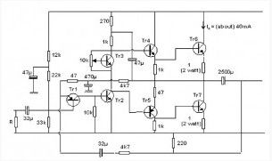
This circuit can have a power output of 10 Watt. It simply uses ordinary transistors. The 10 w amplifier circuit is unstable if the input is not connected. When performing the test, connect a resistor (about 3k3).
(View)
View full Circuit Diagram | Comments | Reading(1637)
Voltage Controlled Amplifier
Published:2013/3/14 2:47:00 Author:Ecco | Keyword: Voltage Controlled Amplifier
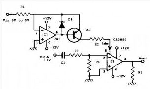
This Voltage Controlled Amplifier circuit is simply an op amp having an additional input at pin 5. A current ILsc is inserted into this input which controls the gain of the device linerly. Thus by inserting an audio signal(±10 mV) within pin 2 and 3 and with controlling the current on pin 5, the amount of the signal output (pin 6) is controlled.
(View)
View full Circuit Diagram | Comments | Reading(0)
Guitar Pre-amp based on an FET BF245 and BF256
Published:2013/3/14 2:45:00 Author:Ecco | Keyword: Guitar Pre-amp , FET
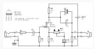
Guitar preamp, based on an FET BF245 and BF256 type. Very easy to build, operate with 9 V battery. Unlikeprevious FET based Guitar pre amp which has gain of close to 1, which is presented here provide the gain (if all goes well).
Guitar preamp InputThe input impedance is mainly determined by the value of R1 and R2, the FET with an input impedance of several tens of MOhm. It is approximately 1 MB and corresponds more or less, even to the value of R2. The coupling between the sensor (microphone) and FET guitar is done through the capacitive coupling capacitor C1 associated with R2 forms a highpass filter whose cutoff frequency is low enough (about 30 Hz at -3 dB with a slope 6 dB / octave).
(View)
View full Circuit Diagram | Comments | Reading(5079)
5.8 W Audio Power Amplifier
Published:2013/3/14 2:42:00 Author:Ecco | Keyword: 5.8 W, Audio Power Amplifier
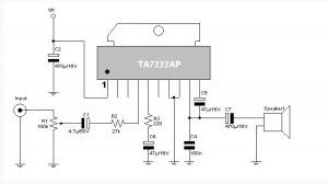
This TA7222AP scheme used for audio signal amplifiers. The circuit delivers 5.8 W with power off Control. 8-12V power supply can be used for this circuit ant it is a good idea to use for car audio amplifier, coin-op gaming machines, security systems, etc.
(View)
View full Circuit Diagram | Comments | Reading(1604)
Voltage controlled variable gain amplifier
Published:2013/3/14 2:41:00 Author:Ecco | Keyword: Voltage controlled , variable gain amplifier
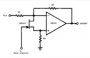
The Voltage controlled variable gain amplifier circuit is built with ic op amp type LM101. The 2N5457 works as a voltage variable resistor having an Rds(on) max of 800 ohms.
Because the differential voltage on the LM101 is within the low mV range, the 2N5457 JFET will have linear resistance over several decades of resistance giving a good electronic gain control.
(View)
View full Circuit Diagram | Comments | Reading(0)
Absolute Value Amplifier
Published:2013/3/14 2:40:00 Author:Ecco | Keyword: Absolute Value Amplifier
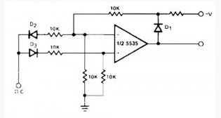
The Absolute Value Amplifier circuit basedoperational amplifier chip 5535. This circuit can provide a positive output voltage for both polarity of input. For positive signals, it acts as a non-inverting amplifier for negative signals, as an inverting amplifier.
The accuracy is poor for input voltages under 1 V, however for less stringent applications, it can be and effective.
(View)
View full Circuit Diagram | Comments | Reading(0)
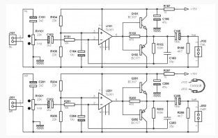
32 ohm Headphones Amplifier
Published:2013/3/14 2:38:00 Author:Ecco | Keyword: 32 ohm , Headphones Amplifier
Here’s a little extra amplifier and really easy to make and inexpensive. It can also serve for a stereo headset (with cables completely separate left and right) for two small low-power headphone.
This 32 ohm Headphones Amplifier circuit built with an IC which consists of four op amps (TL074, TL084 and LM324). This amplifier circuit produces power 30 mW x 2 (1 stereo output for headphones 32 ohms) with a supply voltage + / -4.5 V (two 4.5 V batteries).
For each of the two channels, two op amp are connected in bridge amplifier, to provide headphones a voltage double that which would have been obtained with a single op amp. And in this type of wiring, which said dual voltage power quad also said, for the same load impedance. The same principle adopted by some manufacturers of car radios or amplifiers for high power while making use of reasonable voltages (more bridge circuit).
(View)
View full Circuit Diagram | Comments | Reading(1771)
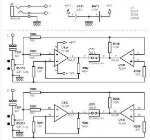
Small stereo headphone amplifier
Published:2013/3/14 2:37:00 Author:Ecco | Keyword: Small , stereo headphone amplifier
A small stereo headphone amplifier cheap and very nice features (without HIFI). It only uses a single power supply value between 15 V and 24 V (you can even lower up to 12 V, but with a less backup).The total gain is determined by the ratio of resistors R102 / R101 for the left channel (top half of the diagram), and R202 / R201 for the right channel (lower half of the diagram), and is about 5 in this case (about 15 dB). Capacitors C103 and C203 may seem unnecessary to some, but mounting low gain can also oscillate, and these two capacitors limit the risk that happening.
Power is single, despite the presence of op amp, with the polarization to VCC / 2 of their non-inverting input (virtual ground composed of R104 / R105 and R204 / R205). A small supply decoupling consists of couples R107 / R207 and C106 / C206 reduces the internal resistance of the power supply and get a better response to transistions fast. The separation of the two left and right channels is also improved slightly (less crosstalk)
(View)
View full Circuit Diagram | Comments | Reading(1367)
Microphone Preamplifier based TLC251
Published:2013/3/14 2:36:00 Author:Ecco | Keyword: Microphone Preamplifier
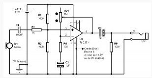
Mic Preamplifier described here is designed for dynamic type microphones, the impedance between 200 ohms and 1 ohm. Its uniqueness lies in the low power consumption, no more than 30 uA in the “worst” case, and make it very portable for this, powered by 1.5 V battery which will allow for longer operating time. This scheme is based on records from the Texas Instruments application.
TLC251 is a Programmable Low-Power Operational Amplifiers. This is indeed a control input, called BIAS (pin 8), which determines the mode of operation. When the pin is worn on the positive potential of power supply, the consumption of the circuit is reduced to a minimum, which is 10 uA (ten micro-amps). When the pin is taken to the potential 0V (ground), the consumption of the circuit back to 30 uA, three times greater than in low power mode. Why you should choose the mode in which consumption is more important? Because of bandwidth. In low power mode, the latter reduced to about 5 KHz trickle to the upper limit, while it increased to more than 20 KHz in another mode. Consider the possibility of intermediate mode, when the terminal 8 (BIAS) increased to 0.75 V, half the supply voltage.
(View)
View full Circuit Diagram | Comments | Reading(2398)
Dual astable multivibrator using 556
Published:2013/3/14 1:46:00 Author:Ecco | Keyword: Dual astable multivibrator
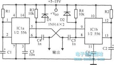
Dual astable multivibrator using 556 is shown as figure.
(View)
View full Circuit Diagram | Comments | Reading(2422)
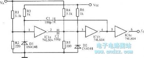
The square wave generating circuit using op amp
Published:2013/3/14 1:41:00 Author:Ecco | Keyword: square wave generating, op amp
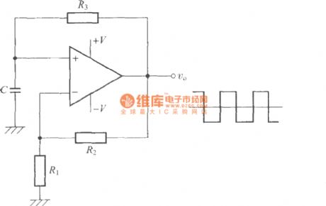
The square wave generating circuit using op amp is shown as figure.
(View)
View full Circuit Diagram | Comments | Reading(1183)
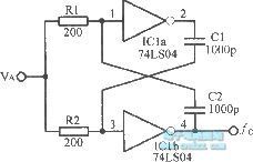
Programmable astable multivibrator
Published:2013/3/14 1:43:00 Author:Ecco | Keyword: Programmable astable multivibrator
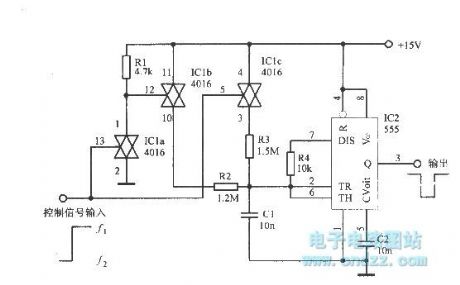
Programmable astable multivibrator is shown as figure.
(View)
View full Circuit Diagram | Comments | Reading(1571)
The switching harmonic crystal oscillator
Published:2013/3/7 2:34:00 Author:Ecco | Keyword: switching, harmonic , crystal oscillator
The switching harmonic crystal oscillator is shown as figure.
(View)
View full Circuit Diagram | Comments | Reading(1293)
Voltage controlled multivibrator circuit
Published:2013/3/14 1:38:00 Author:Ecco | Keyword: Voltage controlled multivibrator
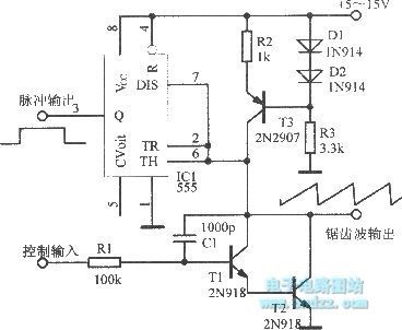
Voltage controlled multivibrator circuit is shown as figure.
(View)
View full Circuit Diagram | Comments | Reading(1229)
The voltage controlled TTL symmetrical multivibrator
Published:2013/3/14 1:45:00 Author:Ecco | Keyword: voltage controlled, TTL symmetrical multivibrator
The voltage controlled TTL symmetrical multivibrator is shown as figure.
(View)
View full Circuit Diagram | Comments | Reading(1171)
Oscillator circuit using LM3900
Published:2013/3/14 1:51:00 Author:Ecco | Keyword: Oscillator
Oscillator circuit using LM3900 is shown as figure.
(View)
View full Circuit Diagram | Comments | Reading(1158)
| Pages:150/2234 At 20141142143144145146147148149150151152153154155156157158159160Under 20 |
Circuit Categories
power supply circuit
Amplifier Circuit
Basic Circuit
LED and Light Circuit
Sensor Circuit
Signal Processing
Electrical Equipment Circuit
Control Circuit
Remote Control Circuit
A/D-D/A Converter Circuit
Audio Circuit
Measuring and Test Circuit
Communication Circuit
Computer-Related Circuit
555 Circuit
Automotive Circuit
Repairing Circuit