
Circuit Diagram
Index 160
LED DICE (with Slow Down) Circuit
Published:2013/3/5 0:24:00 Author:Ecco | Keyword: LED DICE
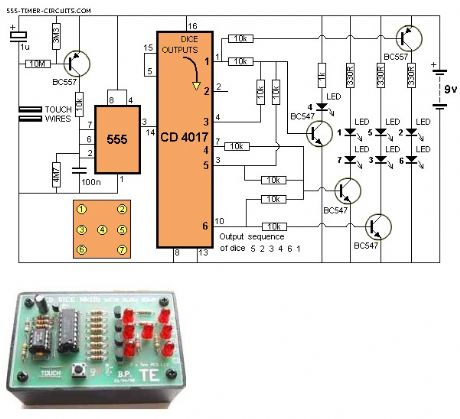
This circuit produces a random number from 1 to 6 on LEDs that are similar to the pips on the side of a dice. When the two TOUCH WIRES are touched with a finger, the LEDs flash very quickly and when the finger is removed, they gradually slow down and come to a stop.
(View)
View full Circuit Diagram | Comments | Reading(2354)
LATCH Circuit
Published:2013/3/5 0:23:00 Author:Ecco | Keyword: LATCH
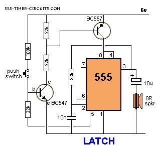
This circuit is a LATCH and remains ACTIVE when the push-button has been pressed for an INSTANT and released.
(View)
View full Circuit Diagram | Comments | Reading(2027)
LASER RAY Circuit
Published:2013/3/5 0:22:00 Author:Ecco | Keyword: LASER RAY
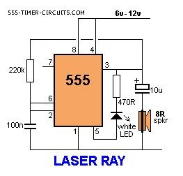
This circuit produces a weird Laser Ray sound and flashes a white LED at approx 5Hz:
(View)
View full Circuit Diagram | Comments | Reading(1223)
KNIGHT RIDER Circuit
Published:2013/3/5 0:21:00 Author:Ecco | Keyword: KNIGHT RIDER
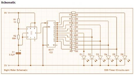
This circuit mimics the lights in knight rider's car. They flash one at a time chasing each other. Overview In the Knight Rider circuit, the 555 is wired as an oscillator (Astable mode). The output of the 555 is directly connected to the input of a 4017 decade counter. The input of the 4017 counter is called the CLOCK line. The 10 outputs Q0 to Q9 become active, one at a time, on the rising edge of the waveform from the 555. Each output can deliver about 20mA but a LED should not be connected to the output without a current-limiting resistor (100R or 220R). Using six 3mm LEDs, the display can be placed in the front of a model car to give a very realistic effect. The same outputs can be taken to driver transistors to produce a larger version of the display.
(View)
View full Circuit Diagram | Comments | Reading(2699)
HEE HAW SIREN Circuit
Published:2013/3/5 0:20:00 Author:Ecco | Keyword: HEE HAW SIREN
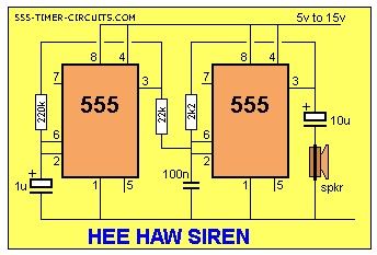
Build the circuit and listen. Change the resistors and capacitors to get all sorts of different results.
(View)
View full Circuit Diagram | Comments | Reading(1040)
FLASHING RAILROAD LIGHTS Circuit
Published:2013/3/5 0:04:00 Author:Ecco | Keyword: FLASHING RAILROAD LIGHT
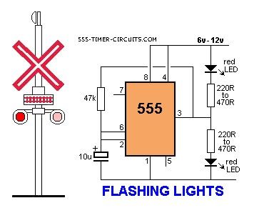
This circuit flashes two red LEDs for a model railway crossing.
(View)
View full Circuit Diagram | Comments | Reading(3689)
Flashing LED Circuit
Published:2013/3/5 0:03:00 Author:Ecco | Keyword: Flashing LED
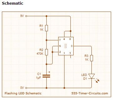
This circuit uses the 555 timer in an Astable operating mode which generates a continuous output via Pin 3 in the form of a square wave. This turns the LED (D1) on and off. The speed at which the LED (D1) is turned on and off is set by the values of R1 and R2.
(View)
View full Circuit Diagram | Comments | Reading(1486)
FLASHING INDICATORS Circuit
Published:2013/3/4 21:49:00 Author:Ecco | Keyword: FLASHING INDICATORS
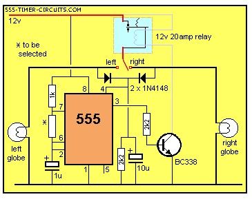
Need to flash turn indicators using a 555 and a single 20 amp relay. Here is our suggestion. The timing resistor needs to be selected for the appropriate flash-rate.
(View)
View full Circuit Diagram | Comments | Reading(1247)
DUMMY ALARM Circuit
Published:2013/3/4 21:48:00 Author:Ecco | Keyword: DUMMY ALARM
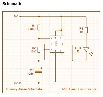
This Dummy Alarm project makes an LED flash briefly once every 5 seconds to imitate the indicator light of a real alarm. Overview The circuit is designed to use very little current to prolong battery life so that it can be left on permanently. An on/off switch is not included, but could be added if you wish. The 7555 timer IC used is a low power version of the standard 555 timer. A 憇uperbright?red LED is used because this provides a bright flash with a low current. The LED is off for most of the time so the average total current for the circuit is less than 0.2mA. With this very low current a set of 3 alkaline AA cells should last for several months, maybe as long as a year.
(View)
View full Circuit Diagram | Comments | Reading(1401)
DRIVING MANY LEDS Circuit
Published:2013/3/4 21:47:00 Author:Ecco | Keyword: DRIVING MANY LEDS
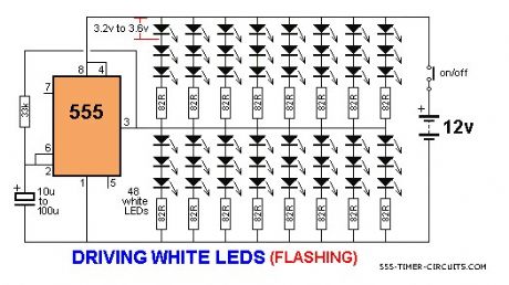
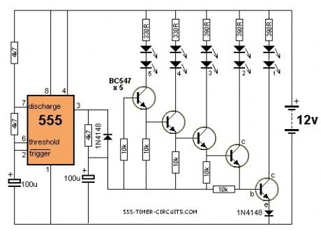
The 555 is capable of sinking and sourcing up to 200mA, but it gets very hot when doing this on a 12v supply. The following circuit shows the maximum number of white LEDs that can be realistically driven from a 555 and we have limited the total current to about 130mA as each LED is designed to pass about 17mA to 22mA maximum. A white LED drops a characteristic 3.2v to 3.6v and this means only 3 LEDs can be placed in series.
(View)
View full Circuit Diagram | Comments | Reading(2379)
DRIVING A RELAY Circuit
Published:2013/3/4 21:44:00 Author:Ecco | Keyword: DRIVING A RELAY
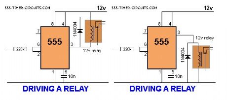
The 555 will activate a relay. When pins 2 and 6 are connected as an input, the chip requires only about 1uA to activate the output. This is equivalent to a gain of about 200,000,000 (200 million) and represents about 4 stages of amplification via transistors.In the first circuit,the output will be opposite to the input. The relay can be connected high or low as show in the second diagram. One point to note: The input must be higher than 2/3V for the output to be low and below 1/3V for the output to be high. This is called HYSTERESIS and prevents any noise on the input creating relay chatter.
(View)
View full Circuit Diagram | Comments | Reading(1242)
DRIVING A BI-COLOUR LED Circuit
Published:2013/3/4 21:43:00 Author:Ecco | Keyword: DRIVING A BI-COLOUR LED
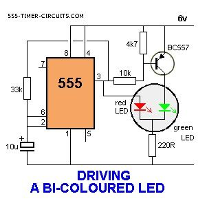
Some 3-leaded LEDs produce red and green. This circuit alternatelyflashes a red/green bi-coloured LED: (View)
View full Circuit Diagram | Comments | Reading(1692)
DARK DETECTOR Circuit
Published:2013/3/4 21:36:00 Author:Ecco | Keyword: DARK DETECTOR
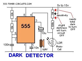
When the level of light on the photo-cell decreases, the 555 is activated. Photo-cells (Photo-resistors) have a wide range of specifications. Some cells go down to 100R in full sunlight while others only go down to 1k. Some have a HIGH resistance of between 1M and others are 10M in total darkness. For this circuit, the LOW resistance (the resistance in sunlight) is the critical value.More accurately, the value for a particular level of illumination, is the critical factor. The sensitivity pot adjusts the level at which the circuit turns on and allows almost any type of photo-cell to be used.
(View)
View full Circuit Diagram | Comments | Reading(2625)
CONTINUITY TESTER Circuit
Published:2013/3/4 21:35:00 Author:Ecco | Keyword: CONTINUITY TESTER
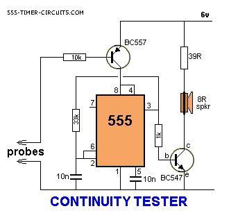
This circuit will detect low resistances and high resistances to produce a tone from the speaker. It will detect up to 200k and the circuit automatically turns off when the probes are not used.
(View)
View full Circuit Diagram | Comments | Reading(2662)
Hulda Clark's Zapper Circuit
Published:2013/3/4 21:34:00 Author:Ecco | Keyword: Hulda Clark's Zapper
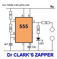

This is the circuit for Dr. Hulda Clark's Zapper, designed in 2003. The frequency is approximately 30kHz positive offset square wave. It has a red LED light that lights up when the unit is on. Perfect for regular zapping, extended zapping and other Hulda Clark related experiments. This device is used tocure, treat and prevent any disease. It will cure anything. Simply hold the two probes (one in each hand) for 5-10 minutes then rest for 20 minutes, then repeat two more times. Do this each day and you will be cured.
On the other side of the coin is the claim that Dr Hulda Clark is a complete quack. Here is a website called: Quackwatch. The second diagram shows the two copper tubes and the circuit in a plastic box. I am still at a loss to see how any energy can transfer from this quack machine, through the skin (50k skin resistance and 9v supply) and zap a bug in your intestine. It's a bit like saying I will kill all the mice in a haystack by stabbing the stack with a needle.
(View)
View full Circuit Diagram | Comments | Reading(0)
CAR TACHOMETER Circuit
Published:2013/3/4 21:32:00 Author:Ecco | Keyword: CAR TACHOMETER
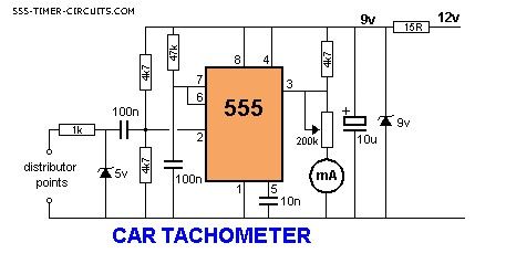
A 555 is configured as a monostable or one shot in this project. The period of the 555 is determined by the 47k and the capacitor from pin 6 to ground (100n). Time T = 1.1 RC or 1.1 X 50,000 X 0.1 X10 -6 = 0.0055 or 5.5 mS (milli-seconds). The 555 receives trigger pulses from the distributor points. These are limited by the 1k and 5v zener diode. These are AC coupled to the trigger input through the 100n coupling capacitor. The 50mA meter receives pulses of current through the 200k pot to show a reading.
(View)
View full Circuit Diagram | Comments | Reading(1837)
BI-POLAR LED DRIVER Circuit
Published:2013/3/4 21:30:00 Author:Ecco | Keyword: BI-POLAR LED DRIVER

Some 2-leaded LEDs produce red and green. These are called Bi-polar LEDs. This circuit alternatelyflashes a red/green bi-polar LED:
(View)
View full Circuit Diagram | Comments | Reading(1522)
Bike Turning Signal Circuit
Published:2013/3/4 21:29:00 Author:Ecco | Keyword: Bike Turning Signal
This circuit can be used to indicate left and right turn on a motor-bike. Two identical circuits will be needed, one for left and one for right.
(View)
View full Circuit Diagram | Comments | Reading(1202)
AUTOMATIC CURTAIN CLOSER Circuit
Published:2013/3/4 21:28:00 Author:Ecco | Keyword: AUTOMATIC, CURTAIN CLOSER
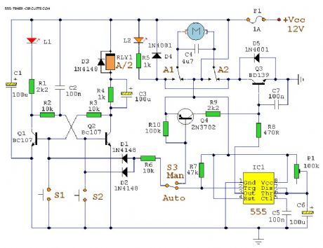
This circuit uses a mixture of transistors, an IC and a relay and is used to automatically open and close a pair of curtains. Using switch S3 also allows manual control, allowing curtains to be left only partially open or closed. The circuit controls a motor that is attached to a simple pulley mechanism, to move the curtains. Automatic OperationThe circuit can be broken into three main parts; a bi-stable latch, a timer and a reversing circuit. Toggle switch S3 determines manual or automatic mode. The circuit as shown above is drawn in the automatic position and operation is as follows. The bi-stable is built around Q1 and Q2 and associated circuitry and controls relay A/2. S1 is used to open the curtains and S2 to close the curtains. At power on, a brief positive pulse is applied to the base of Q2 via C2. Q2 will be on, and activate relay A/2.The network of C3 and R4 form a low current holding circuit for the relay. Relay A/2 is a 12V relay with a 500 ohm coil. It requires slightly less current to keep it energized than it does to operate it. Once the relay has operated, the current through the coil is reduced by R4, saving power consumption. When Q2 is off, C3 will be discharged, but when Q2 becomes active (either at switch-on or by pressing S1) capacitor C3 will charge very quickly via the relay coil. The initial charging current is sufficient to energize the relay and current flow through R4 sufficient to keep it energized.
(View)
View full Circuit Diagram | Comments | Reading(3332)
555 Amplifier Circuit
Published:2013/3/4 21:26:00 Author:Ecco | Keyword: 555, Amplifier
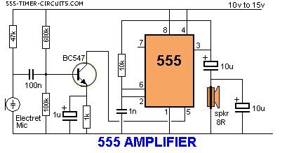
The 555 can be used as an amplifier. It operates very similar to pulse-width modulation. The component values cause the 555 to oscillate at approx 66kHz and the speaker does not respond to this high frequency. Instead it responds to the average CD value of the modulated output and demonstrates the concept of pulse-width modulation. The chip gets very hot and is only for brief demonstrations.
(View)
View full Circuit Diagram | Comments | Reading(2032)
| Pages:160/2234 At 20141142143144145146147148149150151152153154155156157158159160Under 20 |
Circuit Categories
power supply circuit
Amplifier Circuit
Basic Circuit
LED and Light Circuit
Sensor Circuit
Signal Processing
Electrical Equipment Circuit
Control Circuit
Remote Control Circuit
A/D-D/A Converter Circuit
Audio Circuit
Measuring and Test Circuit
Communication Circuit
Computer-Related Circuit
555 Circuit
Automotive Circuit
Repairing Circuit