
Circuit Diagram
Index 1902
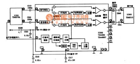
TV video amplifier circuit diagram 3
Published:2011/5/11 1:54:00 Author:Ecco | Keyword: TV video , amplifier
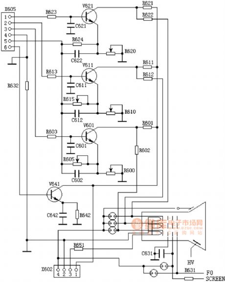
TV video amplifier circuit diagram 3
(View)
View full Circuit Diagram | Comments | Reading(1158)
TV video amplifier circuit diagram 2
Published:2011/5/11 1:55:00 Author:Ecco | Keyword: TV video , amplifier
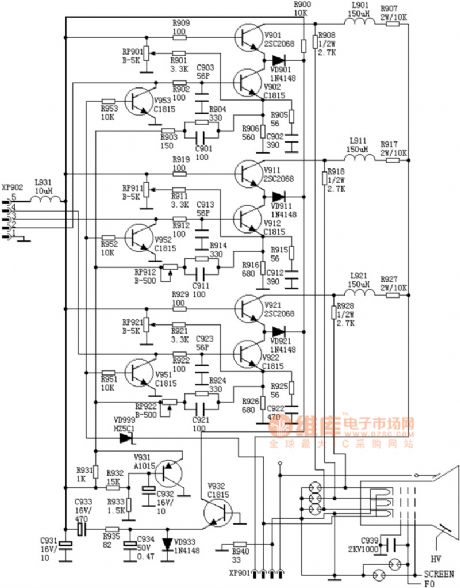
TV video amplifier circuit diagram 2
(View)
View full Circuit Diagram | Comments | Reading(1201)
TV video amplifier circuit diagram 1
Published:2011/5/11 1:56:00 Author:Ecco | Keyword: TV video , amplifier
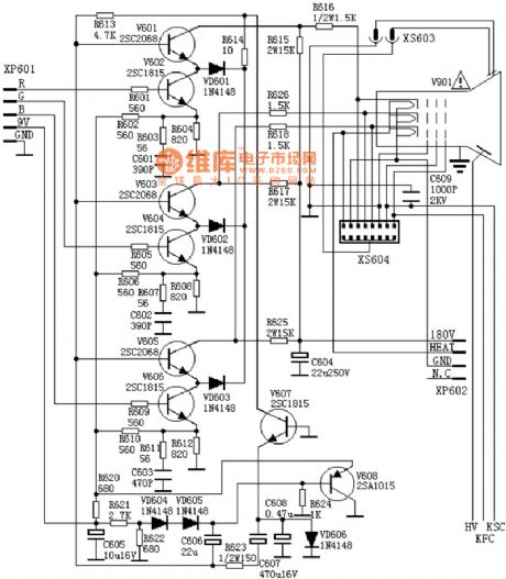
TV video amplifier circuit diagram 1
(View)
View full Circuit Diagram | Comments | Reading(814)
Digital voltmeter circuit diagram composed of ICL7117
Published:2011/5/11 2:49:00 Author:Ecco | Keyword: Digital , voltmeter
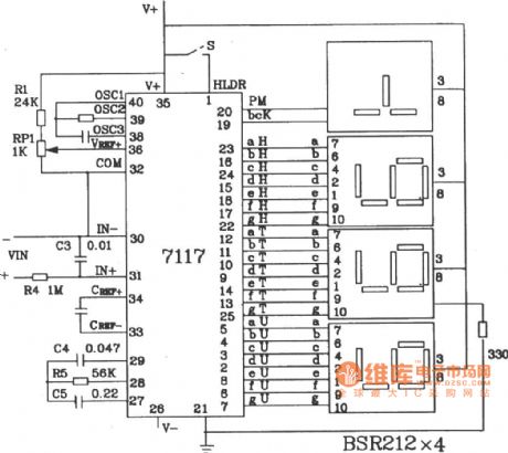
Digital voltmeter circuit diagram composed of ICL7117 3 1 / 2 double integral A / D converter is shown as the chart.
(View)
View full Circuit Diagram | Comments | Reading(4236)
Digital voltmeter circuit diagram composed of ICL7116
Published:2011/5/11 2:51:00 Author:Ecco | Keyword: Digital , voltmeter

Digital voltmeter circuit diagram composed of ICL7116 3 1 / 2 double integral A / D converter is shown as the chart.
(View)
View full Circuit Diagram | Comments | Reading(2673)
DC isolation circuit daigram with harmonic suppression
Published:2011/5/11 4:00:00 Author:Ecco | Keyword: DC , isolation, harmonic suppression
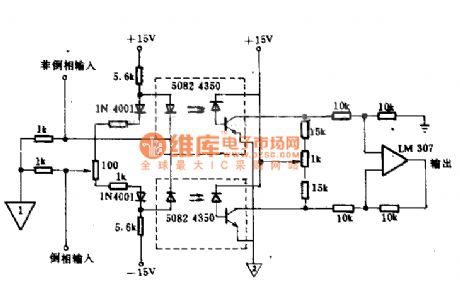
This circuit uses two isolators to reduce the harmonic generation as the working of push-pull amplifier. When it is coupled with the input signal, the gain of one isolation tube will increase, another isolation tube reduces for compensation, then it eliminates harmonics. The gain of the circuit is about 1. When the signal is less than 2 rounds (peak - peak), the bandwidth is 2MHz. The inverting or non-inverting input end can be added any polarity input signal.
(View)
View full Circuit Diagram | Comments | Reading(1114)
Digital voltmeter circuit diagram with single + 5V power supply composed of ICL7107
Published:2011/5/11 3:00:00 Author:Ecco | Keyword: Digital , voltmeter , single, + 5V , power supply
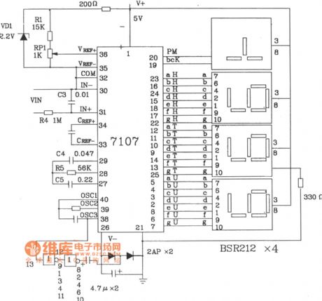
Digital voltmeter circuit diagram with single + 5V power supply composed of ICL7107 3 1 / 2 double integral A / D converter is shown as the chart.
(View)
View full Circuit Diagram | Comments | Reading(11767)
Digital voltmeter circuit diagram composed of ICL7106
Published:2011/5/11 2:57:00 Author:Ecco | Keyword: Digital voltmeter
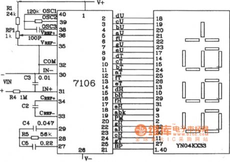
Digital voltmeter circuit diagram composed of ICL7106 3 1 / 2 double integral A / D converter is shown as the chart.
(View)
View full Circuit Diagram | Comments | Reading(16871)
Digital capacitance table circuit diagram composed of ICL7107
Published:2011/5/11 2:31:00 Author:Ecco | Keyword: Digital capacitance table
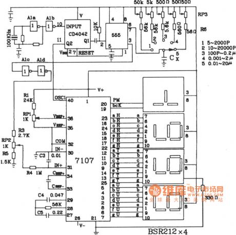
Digital capacitance table circuit diagram composed of ICL7107 is shown as the chart.
(View)
View full Circuit Diagram | Comments | Reading(7638)
Remote control turn-off style intergrated regulated power supply circuit composed of CW7900
Published:2011/5/10 21:25:00 Author:Rebekka | Keyword: Remote control, intergrated regulated power supply , turn-off style
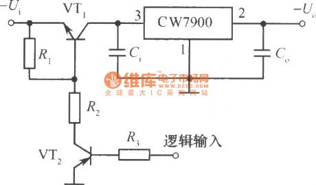
Here is the diagram of Remote control turn-off style intergrated regulated power supply circuit composed of CW7900. (View)
View full Circuit Diagram | Comments | Reading(791)
Light control regulated power supply circuit composed of CW7900
Published:2011/5/10 21:13:00 Author:Rebekka | Keyword: Light control regulated power supply
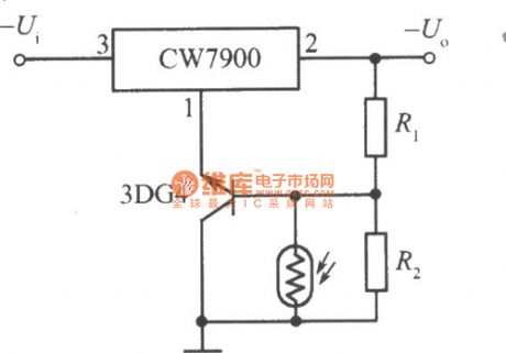
Here is the diagram of Light control regulated power supply circuit composed of CW7900(Output voltage drops in illumination). (View)
View full Circuit Diagram | Comments | Reading(681)
Polymer capacitances-type humidity sensor application circuit
Published:2011/5/10 1:14:00 Author:Fiona | Keyword: Polymer capacitances-type, humidity sensor
Illustration is polymer capacitances-type humidity sensor application circuit.It consists of two time base circuit IC1,IC2 composition.IC1 and external components compose themultivibrator which mainly triggers IC2 's pulse.ICz,capacitance-type humidity sensor and external component compose theadjustable wide pulse generator .The pulse width will depend on the humidity sensor capacitance size.The width pulse output from the IC2's ⑨ feet,filtered by R5, C3, then put out as DC signal.It is proportional to the air'srelative humidity, the sensitivity of 2mv /% RH.
(View)
View full Circuit Diagram | Comments | Reading(529)
Resistance-type condensation sensor application circuit
Published:2011/5/10 1:12:00 Author: | Keyword: Resistance-type, condensation sensor
Illustration is resistance-type condensation sensor application circuit .Shown in figure (a) is positive characteristics condensation sensor application circuit and Shown in figure (b) is negative characteristics condensation sensor application circuit. (View)
View full Circuit Diagram | Comments | Reading(522)
Metal oxides humidity sensor application circuit
Published:2011/5/10 1:00:00 Author: | Keyword: Metal oxides, humidity sensor
The low-frequency oscillator is composed&nbs (View)
View full Circuit Diagram | Comments | Reading(460)
CD2003—AM/FM radio monolithic integrated circuit
Published:2011/5/10 1:14:00 Author:Fiona | Keyword: radio monolithic integrated
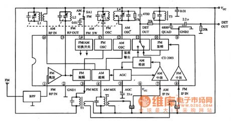
CD2003 is an AM / FM radio monolithic integrated circuit,it has been widely used in the desheng series radio.1. Features
CD2003 integrated circuit contains AM HF amplifier, local oscillator, mixer, IF amplifier and detector circuit ;FM HF amplifier, local oscillator, mixer, IF amplifier and discriminator circuit : and the AGC circuit, AM / FM band selection circuit etc, the block diagram of the in-circuit is shown in Figure 1.
Figure 1 CD2003 integrated circuit within the circuit block diagram and typical application circuit2.pin functions and data
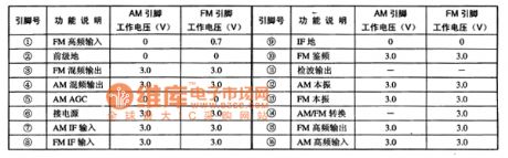
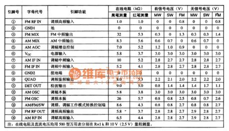
CD2003 integrated circuit uses 16-pin dual in-line Package,the pin functions and typical operating parameters(Vcc = 3V time, the pin voltage in AM and FM both cases,) are listed in table 1,the pin function and the test data on the desheng multi-band radio are listed in the table 2.
Table 1 CD2003 integrated circuit pin functions and typical operating parameters
Table 2 CD2003 integrated circuit pin functions and test data on the desheng multi-band radio
3.Typical application circuit
Illustration 1 is a typical application circuit of AM / FM band radio formed by the CD2003 integrated circuit.the work process1) AM band.The signals received from Antenna input from the CD2003 (16) pin ,mixing with the LO signal in the mixing circuit.The signal obtained output from (4) pin , obtaining the 465kHz IF signal selected by frequency to input from the (7) pin.After being converted by the IF amplification, detection, electronic switch, the signals output from (11) pin to reach the post-stage circuit. (2)FM band.The signals received from Antenna input from the (1) pin after being band-pass filtered by the BPF,added to the mixing circuit after HF amplifier.Mixing with the LO signal in the mixing circuit,the signal obtained output from (3) pin , obtaining the 10.7MHz IF signal selected by frequency to input from the (8) pin.After being converted by the AM / FM electronic switch, the signals output from (11) pin to reach the post-stage circuit.Tip:According to the above-mentioned signal flow ,it's convenient to repair AM or FM radio with sound or radio trouble.Becauce CD2003 will not easily damaged,we should pay attention to the periphery of its three-terminal filters to be checked. (View)
View full Circuit Diagram | Comments | Reading(24516)
Kettle automatic alarm circuit
Published:2011/5/8 19:57:00 Author:Christina | Keyword: Kettle, automatic alarm
When you boil water by the home gas stove, it often spills off the flame by the boiling water, and this leads to gas leak. This is a waste of energy and would cause serious accidents. Use the Kettle automatic alarm which is made by the PTC thermistor, you can prevent the accidents.
1 circuit principle
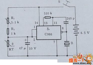
The core of this kettle automatic alarm circuit is composed of the NAND IC block and the PTC thermistor, the circuit principle is as shown in figure 1. Before the water temperature meets the default value, RT's resistance is small, IC's input voltage is lower than the threshold voltage, B will not alarm. When the water temperature meets the boiling point, RT's resistance increase rapidly and higher than the threshold voltage, after 30 seconds, IC outputs the voice signal and B issues the alarm.
Figure 1. Kettle automatic alarm circuit
2 Select the main components
The Kettle automatic alarm circuit's RT temperature probe uses the PTC thermistor, the room temperature resistance is ≤500Ω, the standard resistance - temperature characteristic curve is as shown in figure 2.8.2. Buzzer B uses the Ф27mm.
Figure 2. The standard resistance - temperature characteristic curve
3 Installation and Commissioning
When you use it, put the temperature sensor end into the kettle, the alarm installed in the place where is easy to hear the alarm sound, and notic the moisture. (View)
View full Circuit Diagram | Comments | Reading(1685)
Low noise good precision magnetic head amplifier (AD797) circuit
Published:2011/5/10 2:23:00 Author:TaoXi | Keyword: Low noise, good precision, magnetic head amplifier
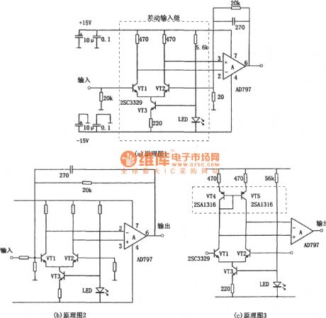

The low noise good precision magnetic head amplifier (AD797) circuit is as shown. These three circuits have different input modes. In figure (a), the input signal with the single-ended input mode adds to the current source-type differential amplifier circuit which is composed of the transistors, and this circuit outputs the signal with differential amplifier mode to the op amp AD797's two input ports (pins 2,3). This circuit uses the differential amplifier which is composed of the transistor structure with excellent performance, so this circuit has high signal to noise ratio (S/N) and can process the signal with larger dynamic range. In figure (a), the three transistors are 2SC3329, VT3 is the constant current tube, VT1 and VT2 are the differential amplification tube. Add the 20kΩ feedback resistor and the 270pF compensation capacitor between the op amp AD797's output port (pin 6) and VT2's base pin. Feedback resistor of the 20Ω resistance from VT2 to ground and the 20kΩ feedback resistor decide the voltage gain, the 270pF compensation capacitor improves the stability of the circuit. You need to add two resistances (10μF electrolytic capacitor and 0.1μF organic synthetic membranes capacitance) between the positive and negative power supply terminals (pin 7,4) and the ground as the decoupling capacitor. You can filter the high-frequency interference and the low-frequency interference in this way.
(View)
View full Circuit Diagram | Comments | Reading(2659)
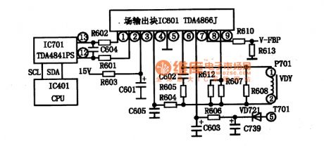
TDA4665/4665T integrated block internal box circuit and Haier 692-733AA color TVs typical application circuit
Published:2011/5/10 22:44:00 Author:TaoXi | Keyword: integrated block, internal box, typical application
2.Pin functions and data
The switching power supply with the operating frequency of 500khz is composed of the TDA4605 and the FET switch tube, so the switching power supply has the high efficiency.
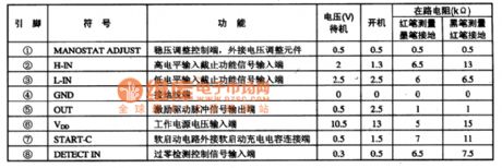
The TDA4605 is in the 8-pin package, the pin functions and data is as shown in table 12.
Table 12 The pin functions and data of the TDA4605
(View)
View full Circuit Diagram | Comments | Reading(2072)
Integrated block typical application circuit
Published:2011/5/9 3:05:00 Author:TaoXi | Keyword: Integrated block, typical application
2. Pin functions and data
The TDA4661 and TDA4661V2 are in the 18-pin package that can be used in related models, the pin functions and dataare as shown in table 14.
Table 14 Test data of the TDA4661V2 in different related models
(View)
View full Circuit Diagram | Comments | Reading(604)
TB1251N video small signal processing monolithic integrated circuit
Published:2011/5/8 6:47:00 Author:TaoXi | Keyword: video, small signal processing, monolithic
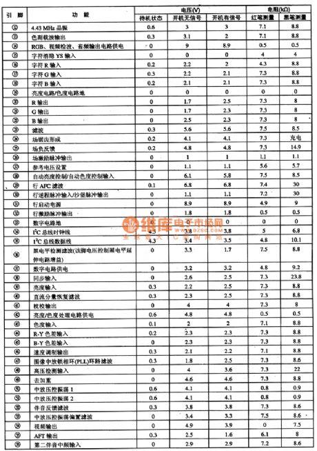
The TB1251N is designed as one kind of video small signal processing monolithic integrated circuit that is produced by the TOSHIBA company, and it can be used in the various types of domestic and imported color TV such as the Changhong CN-15 movement series large screen color TV.
1.Features
The TB1251N has the image and sound amplifier circuit, the color demodulation circuit, the luminance signal processing circuit, the line scanning and field scanning small signal processing circuit, the I2C bus interface circuit, the VCO circuit, the high voltage test and protection circuit and other circuits.
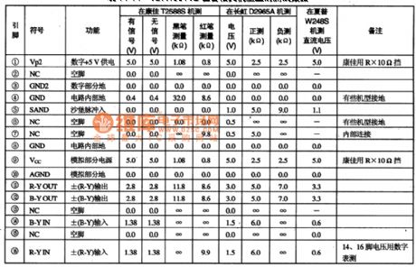
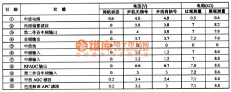
2.Pin functions and data
The TB1251N is in the 56-pin package, the pin functions and data of this circuit is as shown in table 1.
Table 1 The pin functions and data of the TB1251N (View)
View full Circuit Diagram | Comments | Reading(571)
| Pages:1902/2234 At 2019011902190319041905190619071908190919101911191219131914191519161917191819191920Under 20 |
Circuit Categories
power supply circuit
Amplifier Circuit
Basic Circuit
LED and Light Circuit
Sensor Circuit
Signal Processing
Electrical Equipment Circuit
Control Circuit
Remote Control Circuit
A/D-D/A Converter Circuit
Audio Circuit
Measuring and Test Circuit
Communication Circuit
Computer-Related Circuit
555 Circuit
Automotive Circuit
Repairing Circuit