
Circuit Diagram
Index 1909
High voltage internal compensation op amp circuit
Published:2011/5/9 10:07:00 Author:Christina | Keyword: High voltage, internal compensation, op amp
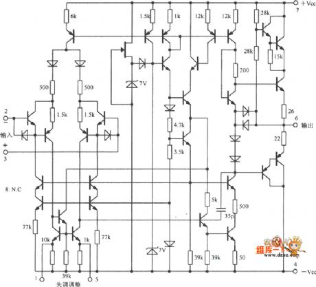
The High voltage internal compensation op amp circuit is as shown:
(View)
View full Circuit Diagram | Comments | Reading(2885)
The Light Vehicle Circuit of Nanjing NAVECO Ⅱof S Series
Published:2011/5/10 21:55:00 Author:Borg | Keyword: Light Vehicle, NAVECO
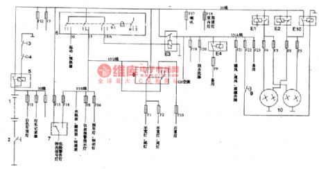

2.instructions of the wiring and principle circuit of Nanjing NAVECO lightweight car(shown in Figure 2 to Figure 9)
(1)in the above figure, the box of thick lines means the positions of the internal wires of the central box,relays,fuses and connectors.
(2)the points of intersected by the thick line under the central box and wires out of it were represented by letters and numbers, which means the positions of connectors and their wires.
(3)the serial numbers noted with 5 digits, which are put above or under the component drawing. The meanings of these 5 digits can be summerized into certain areas,such as speedmeter sensors:
the meanings of component classification designations:
0-engine,starter; 1-motor,heater; 2-relays,batteries; 3-lights; 4-instrument,sensors, tachometer 5-switches,indicators; 6- body system,wiper/washer and so on; 7-central control box, wiring componet; 8-cigrette lighter, friction plate sensor (View)
View full Circuit Diagram | Comments | Reading(459)
Typical application circuit of the single-phase electric power measurement system SM9903
Published:2011/5/10 19:08:00 Author:Christina | Keyword: Typical application, single-phase, electric power measurement
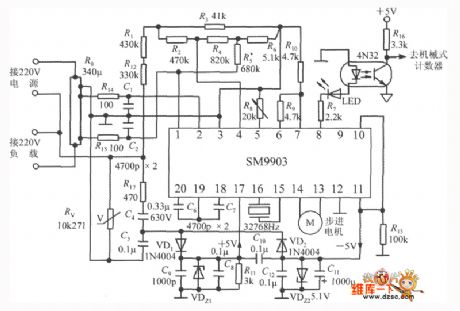
Typical application circuit of the single-phase electric power measurement system SM9903 is as shown. The constant of this watt-hour meter is 1600P/kWh, P corresponds to the 1kWh electricity output pulse, the basic measurement range is 5A, the maximum measurement range is 20A. The 220V alternating current gets through the 340μΩ manganese copper resistance R0 and changes into the current sampling signal, and this signal gets through the precision metal film resistor network and becomes the voltage sampling signal. The 220V alternating current uses the capacitance step-down method to supply power to the circuit, C4 is the step-down capacitance, VDz1 is the regulator tube of the +5V power supplier, VDz2 is the regulator tube of the -5V power supplier. Pin-8 outputs the active power integrated calculate pulse and this pulse is sent to the mechanical counter by optical coupler 4N32. The 32768Hz quartz crystals' frequency stability is 30X 10-6/oC, the equivalent inductance is 0.9mH, the load capacitance is 12.5pF, the equivalent resistance is 35 to 45kΩ. The C6, C7 are the integral capacitance. R8 uses the several-cycle fine-tune resistance. Rv is the 10K271 type thermistor that has the over-voltage protection function. LED is the red led.
(View)
View full Circuit Diagram | Comments | Reading(2504)
Circuit of DC Motor Driver with Resistor Providing A Path of Returning Signal Current
Published:2011/5/10 2:23:00 Author:Felicity | Keyword: DC Motor Driver, Resistor
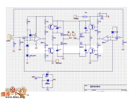
The picture above shows the circuit of DC motor driver with resistor provides a path of returning signal current. (View)
View full Circuit Diagram | Comments | Reading(629)
Capacitors Measured with Composite Pipe Circuit
Published:2011/5/10 2:22:00 Author:Felicity | Keyword: Capacitors Measured with Composite Pipe Circuit,
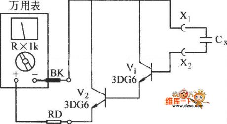
The picture above shows the Capacitors Measured with Composite Pipe Circuit . (View)
View full Circuit Diagram | Comments | Reading(689)
Circuit of Geminate Transistor Measured with Junction Field Effect
Published:2011/5/10 2:20:00 Author:Felicity | Keyword: Circuit, Geminate Transistor, Measured with Junction Field Effect,
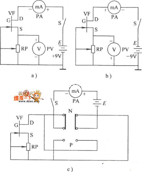
The picture above shows the Circuit of Geminate Transistor Measured with Junction Field Effect. (View)
View full Circuit Diagram | Comments | Reading(772)
Ring wave detector circuit
Published:2011/5/9 10:06:00 Author:Christina | Keyword: Ring wave, detector
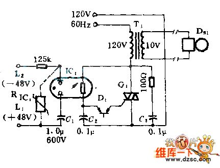
The optical isolator with the neon light and photosensitive resistance can be used as the interface between the telephone line and the ring. The neon light will turn on if there is the 100Vac ring signal, at the same time C1 is isolated to keep the battery voltage range. If we use the varistor RLC1, the rated voltage of the capacitor can be reduced to 400V. The SCR switch Q1 and the line transformer primary series connection supply the 20HZ ringing frequency synchronization for the phone system.
(View)
View full Circuit Diagram | Comments | Reading(598)
Transistor KK110F40 internal circuit
Published:2011/5/9 9:14:00 Author:Christina | Keyword: Transistor, internal circuit
The Transistor KK110F40 internal circuit is as shown:
(View)
View full Circuit Diagram | Comments | Reading(440)
Transistor CTT181GK18 and CTT60GK08 internal circuits
Published:2011/5/9 9:22:00 Author:Christina | Keyword: Transistor, internal circuit
The Transistor CTT181GK18 and CTT60GK08 internal circuitsare as shown:
(View)
View full Circuit Diagram | Comments | Reading(485)
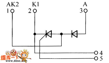
DTMF infrared remote control circuit
Published:2011/5/10 18:51:00 Author:Christina | Keyword: DTMF, infrared, remote control
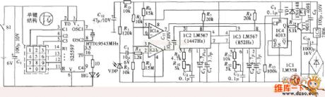
The DTMF infrared remote control circuit. The DTMF encoded signal can be decoded by the special decoder and the PLL audio decoder LM567. But the DTMF encoded signal which is decoded by only one decoder, has only one frequency, one group of control signal is composed by two decoder's output frequency. The infrared remote control signal which is produced by the DTMF launcher is as shown, one channel of the control signal's infrared remote control switch is decoded by two LM567. And this circuit is composed of the twelve channels DTMF coding infrared remote control launcher, the infrared receiving voltage amplifier, the channel signal decoder, the switch controller and the driving circuit.etc.
(View)
View full Circuit Diagram | Comments | Reading(3421)
Transistor CTT181GK12 and CTT181GK16 internal circuits
Published:2011/5/9 9:22:00 Author:Christina | Keyword: Transistor, internal circuit

The Transistor CTT181GK12 and CTT181GK16 internal circuitsare as shown:
(View)
View full Circuit Diagram | Comments | Reading(463)
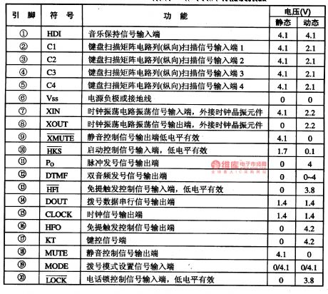
The PC Intergrated Circuit of C807-1354 Communication Single Door
Published:2011/5/10 20:40:00 Author:Borg | Keyword: Intergrated Circuit, Communication, Single Door
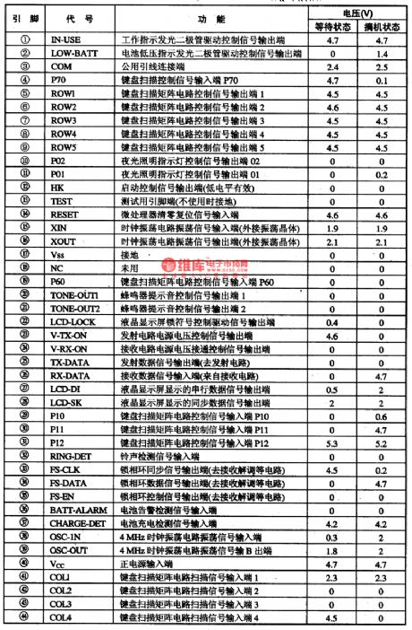
C807一1354 is an PC intergrated circuit of communication single door which is used in wirless phones as the bus master of cell phones.
1.function features
C807一1354 intergrated circuits contain control circuits of wireless delivering/receiving,LCD drive, lighting lamps, key switch encoding/decoding, clock shocking, in it, phase-locked loop signal handling, buzzer drive, code generating and conditioning, low voltage test,charging and othe functions.
2.pin functions and relevent data
C807—1354 intergrated circuits are packaged with 44 pinnings,whose pin functions and data are listed in Table 1.
Table 1 pin functions and data of C807-1354 (View)
View full Circuit Diagram | Comments | Reading(674)
Transistor CTT116GK18 and CTT181GK08 internal circuits
Published:2011/5/9 9:22:00 Author:Christina | Keyword: Transistor, internal circuit

The Transistor CTT116GK18 and CTT181GK08 internal circuitsare as shown:
(View)
View full Circuit Diagram | Comments | Reading(414)
Transistor CTD100GK08 and CTT116GK12 internal circuits
Published:2011/5/9 9:23:00 Author:Christina | Keyword: Transistor, internal circuit

The Transistor CTD100GK08 and CTT116GK12 internal circuits are as shown:
(View)
View full Circuit Diagram | Comments | Reading(446)
Mini radio principle circuit
Published:2011/5/10 19:41:00 Author:Christina | Keyword: Mini radio, principle circuit
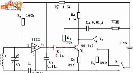
Installation points:
1. Try to close to the circuit board when you are installing the components, and choose the correct vertical and horizontal installation way. 2. The welding time is less than 3 seconds, the special attention should be paid to the earplugs socket, ceramics capacitor, variable capacitor and switch to prevent damage. 3. Take or put the iron coil carefully to prevent the thrum abruptment. You need to remove the paint and add the tin before welding, and the components is fixed by the wax or double-sided adhesive after welding. 4. Try to install the earplugs socket near the lateral, and the installation is flat and exact. 5. The switch installation is flat and exact too. 6. The replacement of the transistor and integrated circuit don't make mistakes, also the pin. 7. You should pay attention to the tin absorption of the printing plate and the electric soldering iron head. Use the rosin reasonablly and avoid the virtual welding, false welding phenomenons. 8. Avoid using too many tin, the contact position of the electric soldering iron head and the circuit board must be accurately.
Welding resistance components:
R1: 100kΩ, color ring: brown black goldR2: about 1.5kΩ, color ring: palm green red goldR3: 33kΩ, color ring: orange orange orange goldR4: 2.7kΩ, color ring: red purple red goldR5: 39Ω, color ring: orange white blackR6: 39Ω, color ring: orange white black
(View)
View full Circuit Diagram | Comments | Reading(1587)
HT9246DL-An Intergrated Circuit of Pulse/Tone Dialing
Published:2011/5/10 20:16:00 Author:Borg | Keyword: Intergrated Circuit, Pulse/Tone Dialing

HT9246DL is an intergrated circuit of pulse/tone dialing which is widely used in wirless phones of multi-channels.
1.functions features
The contents of the HT9246DL intergrated circuit:pulse/tone dialing circuit, key switch signal encoding/decoding circuit, silence control circuit, hand-free control circuit, clock oscillatory circuit and other function circuit.
2.fin functions and relevent data
HT9246DL intergrated circuits are pinned in double-line plastic packages with 28 pinnings, whose pin functions and data are listed in Table 1-1. In the table, the pin voltage value of (19) is 4.1 when the dialing is in the pulse way, and 0V when it is in the tone way.
The static state in Table 1-1. Means off-hook, and the dynamic means that the voltage when application circuits corresponding to pinnings are working.
Table 1-1 pin functions and data of the HT9246DL circuit (View)
View full Circuit Diagram | Comments | Reading(847)
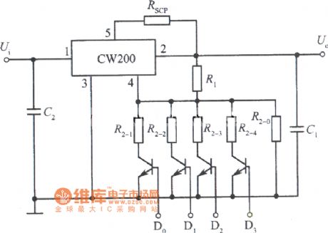
Logic control integrated regulated power supply circuit diagram composed of CW200
Published:2011/5/10 20:47:00 Author:Ecco | Keyword: Logic control , integrated , regulated power supply
View full Circuit Diagram | Comments | Reading(587)
Bipolar reversed circuit diagram composed of ISO100
Published:2011/5/10 20:58:00 Author:Ecco | Keyword: Bipolar , reversed
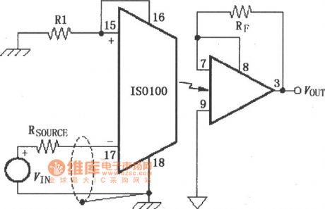
Bipolar reversed circuit diagram composed of ISO100 is shown as the chart. Comparing with unipolar reversed circuit, the connection method of pin 16 and pin 8 in bipolar reversed circuit is different. In bipolar reversed circuit, pin 16 and pin 15 are connected, pin 8 and pin 7 are connected, the other requirements are same to unipolar reversed circuit.
(View)
View full Circuit Diagram | Comments | Reading(586)
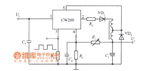
Separately excited switching integrated regulated power supply circuit diagram composed of CW200
Published:2011/5/10 20:30:00 Author:Ecco | Keyword: Separately excited, switching , integrated , regulated power supply
View full Circuit Diagram | Comments | Reading(538)
The Circuit of Capacitors being used as Transformers
Published:2011/5/8 9:18:00 Author:Crystal Liu | Keyword: Capacitors, transformer
The Circuit of Capacitors being used as Transformers
(View)
View full Circuit Diagram | Comments | Reading(447)
| Pages:1909/2234 At 2019011902190319041905190619071908190919101911191219131914191519161917191819191920Under 20 |
Circuit Categories
power supply circuit
Amplifier Circuit
Basic Circuit
LED and Light Circuit
Sensor Circuit
Signal Processing
Electrical Equipment Circuit
Control Circuit
Remote Control Circuit
A/D-D/A Converter Circuit
Audio Circuit
Measuring and Test Circuit
Communication Circuit
Computer-Related Circuit
555 Circuit
Automotive Circuit
Repairing Circuit