
Circuit Diagram
Index 1908
UCC3918 Hot Swap Control Circuit
Published:2011/5/9 9:08:00 Author:Robert | Keyword: Hot Swap, Control
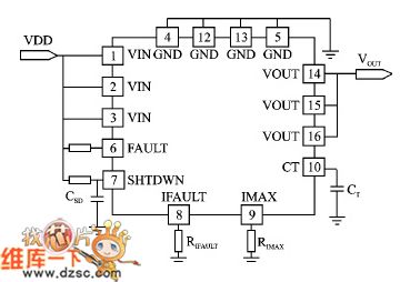
The UCC3918 Hot Swap Control Circuit is shown below.
(View)
View full Circuit Diagram | Comments | Reading(474)
Current Reducing Protection Application Cirrcuit Composed of WB705
Published:2011/5/6 7:57:00 Author:Robert | Keyword: Current Reducing, Protection, Application


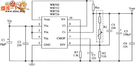
The picture shown below is about the current-reducing protection application cirrcuit with output voltage of 15V and output current of 2A which is composed of WB718 multi-port adjustable positive integrated stabilizer. The input voltage of the circuit in the picture can choose to be 30V~32V. The filter capacitor and vibration-limiting capacitor etc. are the same with those in the application of the current-limiting type. The sample resistance R1 and R2's choice depends on the formula below:The Potentiometer R1 is taken 560Ω and the pull-up resistance is taken 1.2kΩ. The current-limiting resistance is shown in the picture below. In its formula Is is the current value after load is short which is generally taken 1/3ILmax; Vbe, ILmax etc. are the same value with those in the application of current-limiting type. R3's caculation formula is shown in the picture below. In its formula: R10 is the base resistance in the stabilizer internal protection tube which is generally taken 200~250Ω. So These formula's caculation results are approximate. The rest of the circuit is just the same with those in the application circuit of current-limiting type.
(View)
View full Circuit Diagram | Comments | Reading(554)
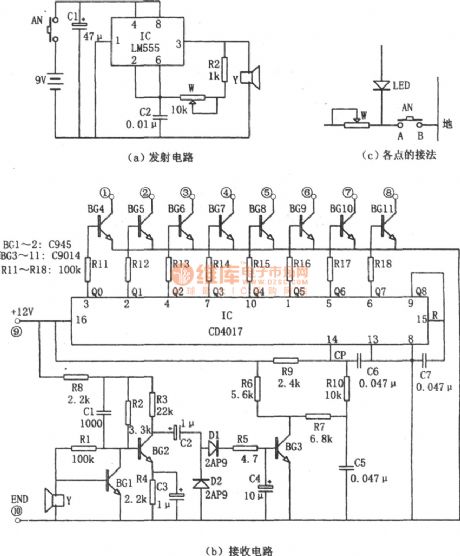
Simple Additional Remote Control Circuit(LM555、CD4017) of Color TV
Published:2011/5/10 1:59:00 Author:chopper | Keyword: Remote Control, Color TV
View full Circuit Diagram | Comments | Reading(1105)
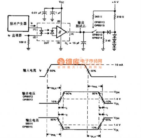
Optical Copuler Switch Sequential Circuit Diagram
Published:2011/5/10 8:08:00 Author: | Keyword: Optical Coupler, Switch, Circuit Diagram
View full Circuit Diagram | Comments | Reading(1036)
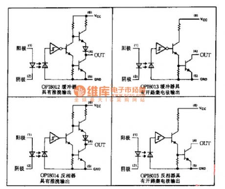
Optical Coupler Series Applied Circuit Diagram
Published:2011/5/10 8:11:00 Author: | Keyword: Optical Coupler Series, Applied Circuit Diagram
View full Circuit Diagram | Comments | Reading(864)
Typical Applied Circuit of M52340SP IC
Published:2011/5/10 19:32:00 Author: | Keyword: IC, Applied Circuit
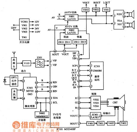
Typical Applied Circuit
The typical applied circuit of M52340SP IC is demonstrated as the abboved picture.Konka F2136 color TV is a typical application example.
Picture:Typical Applied Circuit of M52340SP IC
Note:Ifboth image and sound accompaniment go wrong meanwhile ,we shuold check 38MHz intermediate sequancy signal which is high sequancy singalat first but changed into intermediate then whether it is added to⑥ and ⑦ feet.The M52340SPcircuit will be checked if the signal is normal. (View)
View full Circuit Diagram | Comments | Reading(859)
Remote alarm grating circuit
Published:2011/5/9 9:07:00 Author:Christina | Keyword: Remote alarm, grating
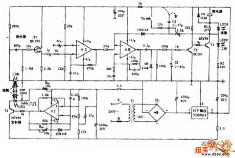
The Remote alarm grating circuit is as shown:
(View)
View full Circuit Diagram | Comments | Reading(522)
human remote sensing fan automatic control circuit
Published:2011/5/9 9:25:00 Author:Christina | Keyword: human remote sensing, fan automatic control

View full Circuit Diagram | Comments | Reading(612)
Application circuit of the op amp
Published:2011/5/9 9:33:00 Author:Christina | Keyword: Application, op amp
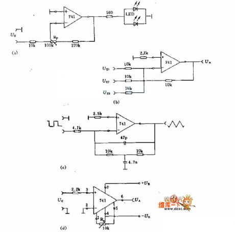
Figure (a) is the polarity monitor with two LEDs, this device can differentiate the polarity of input signal or compare the size of the signal. You can use the potentiometer RP to adjust the sensitivity of the LEDs.
Figure (b) can be used to add the signals of UE1, UE2, UE3.
Figure (c) is the precision integrator circuit, the RC network must match the input signal.
Figure (d) is the comparator circuit.
(View)
View full Circuit Diagram | Comments | Reading(623)
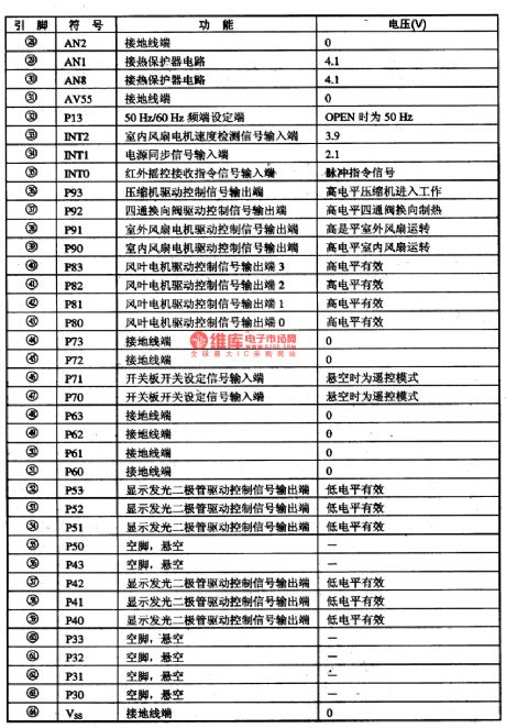
The PC Intergrated Circuit of the C75P036 Air-conditioner
Published:2011/5/10 22:00:00 Author:Borg | Keyword: Intergrated Circuit, Air-conditioner
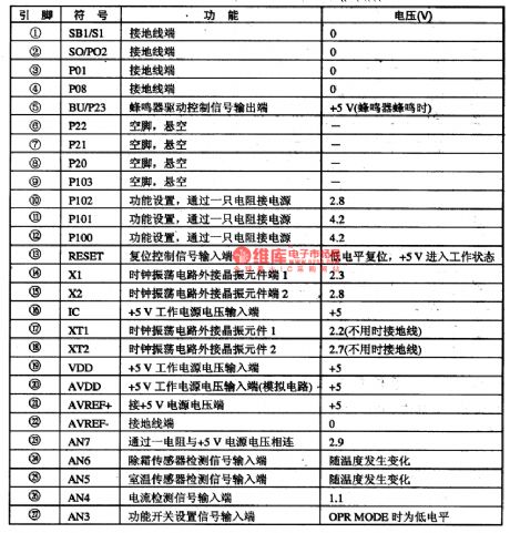
C75P036 is a air-conditioner intergrated circuit specially controled by singal door PCs, which is used in Midea, Hisense, Haier and Geli air-conditioners.
1.function feature
C75P036 consists of three parts, i.e input circuit, central circuit controled by a micro computer and excuting drive circuit, in which the input circuit includes all kinds of signal handling circuit of the sensor test, protection circuit of signal handling and switch order handling circuits, the micro computer control center includes CPU,RAM,ROM and logic computing circuits, the excuting drive circuit includes all kinds of fans, compressors and four-way valve LEDs.
2.pin functions and data
C75P036 intergrated circuits are packaged in a dual in-line way with 64 pinnings, whose pin fuctions and data are listed in Table 1.
Table 1 pin fuctions and data of C75P036 (View)
View full Circuit Diagram | Comments | Reading(1486)
FengHua brand BYD-220 type fridge circuit
Published:2011/5/9 9:08:00 Author:Christina | Keyword: FengHua, fridge circuit
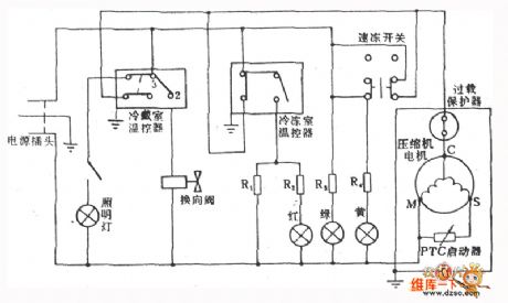
The FengHua brand BYD-220 type fridge circuit is as shown:
(View)
View full Circuit Diagram | Comments | Reading(482)
Two-tone doorbell circuit
Published:2011/5/9 8:48:00 Author:Christina | Keyword: Two-tone, doorbell
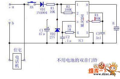
Use the 48V (60V) DC feedback electric current which is provided by the phone feedback line as the working energy of the electronic doorbell is very economical and practical. Now I introduce one kind of two-tone doorbell circuit with out battery. The circuit is as shown, circuit in this figure is the variant of conventional telephone ringing circuit.
a, b are the positive and negative ports of the home telephone line. AN is the normally open doorbell button, when the telephone is in the standby mode, if you press AN, the 48V (or 60V) voltage (which is provided by the PBX) and the DC feedback current will charge capacitor C1 through VD1 and R1, when C1's voltage reaches IC1's start-control voltage, IC1 starts to send out the current of two-tone electronic bell to make the buzzer B sounds, to inform the host when guests are visiting.
When the phone is in using, voltage between a and b can not reaches the IC1's start-control voltage, at this point, even if you press AN, the doorbell button will not work because the R1's value is larger than the telephone's impedance. So if you press AN, there is no effect on the normal call, and also the PBX, but when you use the doorbell, the telephone will be busy. (View)
View full Circuit Diagram | Comments | Reading(2200)
HT9215D-The Intergrated Circuit of PC Dialing
Published:2011/5/10 8:46:00 Author:Borg | Keyword: Intergrated Circuit
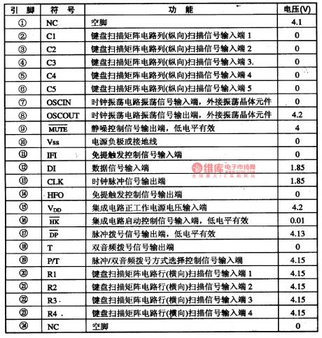
The HT9215D intergrated circuit of PC dialing is widely used in all kinds of phones.
1. Function Features
HT9212D intergrated circuit contains sub circuits of pulse/tone compliant dialing and key switch signal encoding/decoding.
2.pin functions and relevent data
Pin functions and relevent data of the HT9215D intergrated circuit are listed in Table 1-1.
Table 1-1 Pin functions and relevent data of the HT9215D intergrated circuit (View)
View full Circuit Diagram | Comments | Reading(949)
Friendship brand BCD-200 fridge circuit
Published:2011/5/9 9:09:00 Author:Christina | Keyword: Friendship, fridge circuit
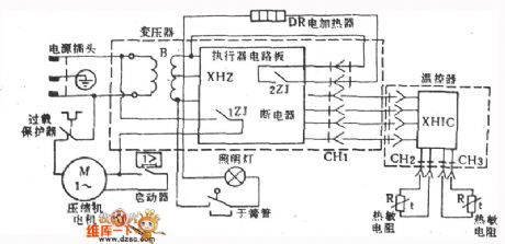
The Friendship brand BCD-200 fridge circuit is as shown:
(View)
View full Circuit Diagram | Comments | Reading(687)
Transistor KK110F80 internal circuit
Published:2011/5/9 9:13:00 Author:Christina | Keyword: Transistor, internal circuit
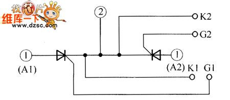
The Transistor KK110F80 internal circuit is as shown:
(View)
View full Circuit Diagram | Comments | Reading(455)
Yellow River BCD-170 type fridge circuit
Published:2011/5/9 9:10:00 Author:Christina | Keyword: Yellow River, fridge circuit
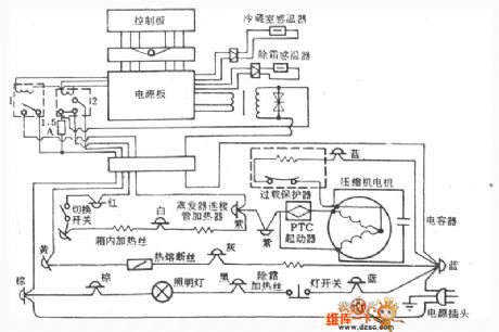
The Yellow River BCD-170 type fridge circuit is as shown:
(View)
View full Circuit Diagram | Comments | Reading(470)
±100mA output current buffer (LF357) circuit
Published:2011/5/10 2:26:00 Author:TaoXi | Keyword: ±100mA, output current, buffer
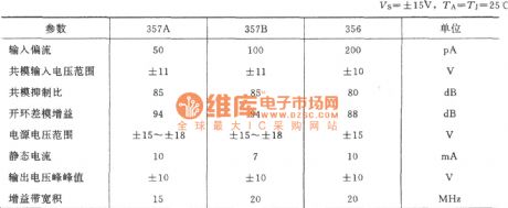
The main parameters (View)
View full Circuit Diagram | Comments | Reading(1325)
water boiling alarm circuit
Published:2011/5/9 9:56:00 Author:Christina | Keyword: water boiling, alarm circuit
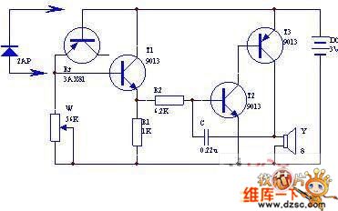
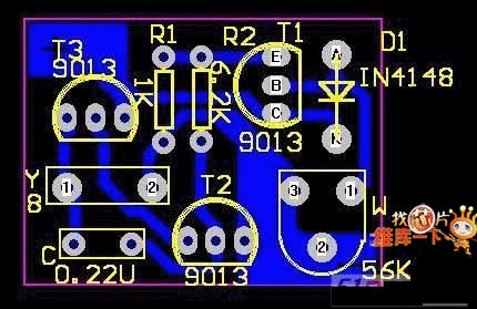
This water boiling alarm circuit is composed of four transistors, the circuit is as shown. The audio oscillator is composed of the transistor T2, T3, the resistor R2 and the capacitor C, the audio signal is output by the speaker.
The switch circuit is composed of the transistor T1, the resistor R1, W and the transistor be node Rt, and it can be used as the audio oscillator control switch.Rt is the temperature sensing element (T1's bias resistor). Usually Rt and T1 are in the reverse cutoff state; when the temperature rises, Rt's reverse resistance gets smaller, the leakage current increases, T1 has some bias to conduct, the audio oscillator starts working and the speaker sounds.
In this figure, transistor T1's magnification needs to be more than 50, T2,T3's magnification needs to be more than 100. The temperature sensor Rt uses the metal shell germanium transistor's be node, such as the 3AX81.etc, also you can use the 2AP-type germanium diode.
(View)
View full Circuit Diagram | Comments | Reading(908)
Adjustable general time relay (NE555, CD4013) circuit
Published:2011/5/9 22:53:00 Author:Christina | Keyword: Adjustable, general, time relay
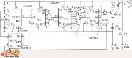
The multifunction of this circuit means it has three operating modes: the delay picking function , the delay releasing function and the delay looping function . The delay picking function means after the pre-boot, the relay will not close. Only when it is the scheduled time, the relay will close. The delay releasing function is the opposite of the delay picking function , after the pre-boot, the relay closes, when it is the scheduled time, the relay will release. The two operations are throwaway, when the relay completes a working process, the control part of the circuit gets into the stable state. The delay looping function is: the circuit will be running with the pre-open interval time and the pre-stop interval time, and it will not stop until you cut off the power or change the working condition. The circuit is as shown.
(View)
View full Circuit Diagram | Comments | Reading(2982)
Air Sensor Circuit Diagram
Published:2011/5/10 2:28:00 Author:Felicity | Keyword: Air Sensor Circuit Diagram,
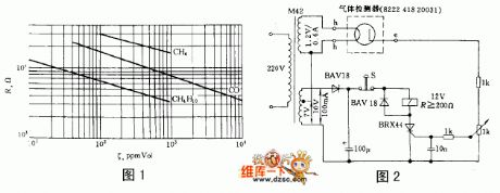
The resistance of some semiconductor decreases dramatically as the temperature increases in the atmosphere of some certain gas. And the performance of some material changes greatly while the gas concentration reaches a certain point. Thus this kind of semiconductor material including ferric oxide, tin oxide and zinc oxide could be made into air sensor. They will react under the atmosphere of methane, butane, ethanol or benzene.
Figure 1 shows the relation curve of the resistance of typical sensor R and the gas concentration P.
The air sensor ,type 8222 418 20031, is made according to this theory. It is consisted of a millimeter-size ceramic plate heating lamp and a electrode opposite to it. The work temperature is 300℃. It can work under both AC and DC condition. Figure 2 shows a simple air warning circuit. While the resistance of the 1kΩcontinuous potentiometer exceed a certain point, the thyristor will be turned on,and then the relay actuate to send a signal or make the actuator off. It is not until the stop button S is pressed that the relay is off again (View)
View full Circuit Diagram | Comments | Reading(669)
| Pages:1908/2234 At 2019011902190319041905190619071908190919101911191219131914191519161917191819191920Under 20 |
Circuit Categories
power supply circuit
Amplifier Circuit
Basic Circuit
LED and Light Circuit
Sensor Circuit
Signal Processing
Electrical Equipment Circuit
Control Circuit
Remote Control Circuit
A/D-D/A Converter Circuit
Audio Circuit
Measuring and Test Circuit
Communication Circuit
Computer-Related Circuit
555 Circuit
Automotive Circuit
Repairing Circuit