
Circuit Diagram
Index 1915
The Alarm Indicator Lamp and Back-up Lamp Circuit of MAZDA 929
Published:2011/5/9 23:02:00 Author:Borg | Keyword: Alarm Indicator Lamp, Back-up Lamp

View full Circuit Diagram | Comments | Reading(734)
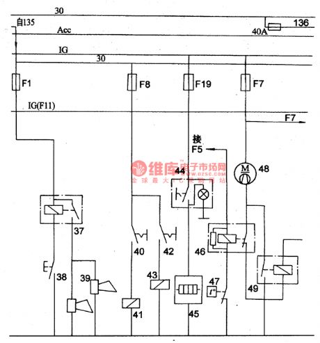
The Wiring Circuit(c) of the Volga 3102 Car
Published:2011/5/10 3:36:00 Author:Borg | Keyword: Wiring Circuit, Volga 3102
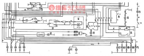
As shown in Figure 9 is the wiring circuit of the Volga 3102 Car.
43-right door lamp; 44-left door lamp; 45-petrol sensor; 46-hand brake switch; 47-rear turing lamp; 48-rear width lamp; 49-brake lamp; 50-back-up lamp; 51-rear fog lamp; 52-ceiling lamp; 53-ceiling lamp switch; 54-warm wingd motor; 55-fan switch; 56-rear heating window; 57-license plate lamp; 58-baggage chamber lamp; 59-staff box lamp; 60-fog lamp relay (View)
View full Circuit Diagram | Comments | Reading(550)
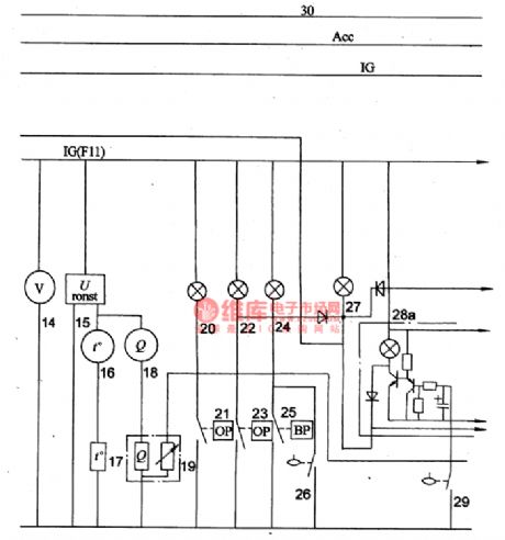
The Instrument and Alarm Lamp Circuit of MAZDA 929
Published:2011/5/9 23:07:00 Author:Borg | Keyword: Instrument, Alarm Lamp
View full Circuit Diagram | Comments | Reading(752)
The Power Supply, Starting and Ignition Circuit of Mazda 929
Published:2011/5/9 23:39:00 Author:Borg | Keyword: Power Supply, Ignition
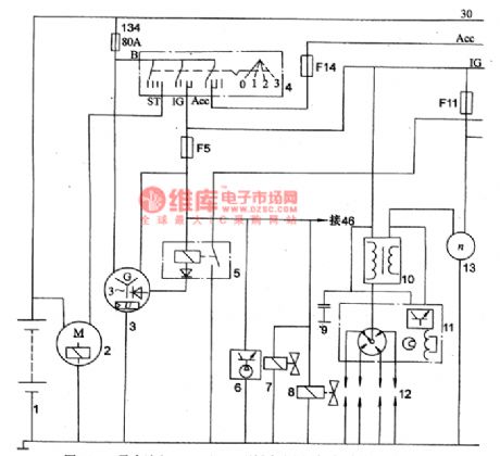
The outside size of Mazda 929 produced by Mazda Motor Corporation of Japan: 4700mm(length)*1690mm(width)*1420mm(height),4 passengers, curb weight:1160kg, total mass:1460kg.
It is equiped with a four-stage carburettor petrel engine of FE type which is installed with water-cooling single overhead camshafts, which has a spherical combustion chamber, and the diameter of its air cylinder is 86mm, piston stroke 86mm,emmission 1998ml, compression ratio∑=8.6,maximum power of the engine 72kW/5600rpm, max Nm 156N.m/3700rpm and idle speed 800~85Orpm.
1. Circuit Diagram
(View)
View full Circuit Diagram | Comments | Reading(1098)
The Intergrated Circuit Driven by the BA6849 Three-phase Spindle Motor
Published:2011/5/9 22:52:00 Author:Borg | Keyword: Intergrated Circuit, Three-phase
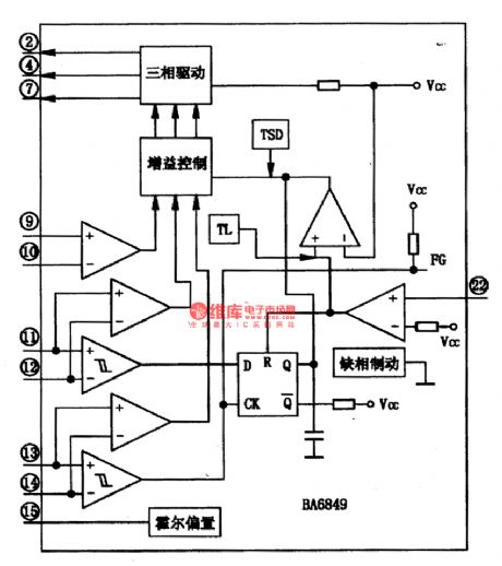
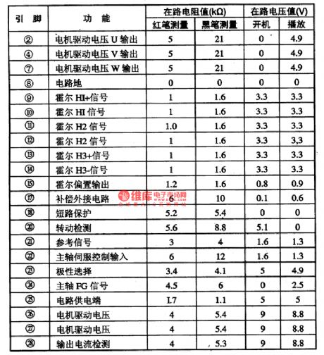
BA6849 is a intergrated circuit diven by the BA6849 three-phase spindle motor, which can translate the defult control signal of the spindle into three-phase drive voltage and therefore drives the three-phase spindle motor. This circuit is used in the cores of DVD players.
As shown in figure 1 is the internal circuit of BA6849 chips, it is pinned in flat type 28 with cooling ribs, the pin functions and data are listed in figure 1 in which the pinnings ①、③、⑤、⑥、(16)、(19) are listed at the foot of the page.
Figure 1. the internal circuit of the BA6849 chip
Table 2. the pin functions and data of the BA6849 chip (View)
View full Circuit Diagram | Comments | Reading(781)
The Brake Lamp,Speaker,Rear Defrost and Cooling Fan Principle Circuit of MAZDA 929
Published:2011/5/10 3:22:00 Author:Borg | Keyword: Brake Lamp, Loud Speaker, Rear Defrost, Cooling Fan
View full Circuit Diagram | Comments | Reading(685)
ZC-2-10A automatic charger circuit
Published:2011/5/10 1:02:00 Author:Nicole | Keyword: automatic charger
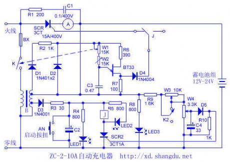
Relaxation oscillator is composed of unijunction transistors BT33、C3、W1、W2 and some components, the produced pulse singal is transported to control pole of SCR1 by isolating diode, the trigger conduction angle of SCR1 can be changed by adjusting W1's resistance, it also changes the changing current. Storage battery charge automatic protection circuit is composed of SCR2, relay J, W3, W4, D5 and some components, when the voltage on both sides of battery is charged to the upper limit value which is set by W3, W4, D5 turns on, SCR2 is triggered to turn on, LED2 displays, relay pulls in, J is switched to normally open, it cuts off SCR1's control pulse integrating, it stops charging to storage battey. K2 is the transfer switch of 12V, 24V changing batteries, as shown in the figure, it is in 12V gear.
(View)
View full Circuit Diagram | Comments | Reading(1194)
4~20mA temperature transmitter circuit diagram composed of TMP35
Published:2011/5/10 4:02:00 Author:Nicole | Keyword: 4~20mA temperature transmitter
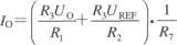
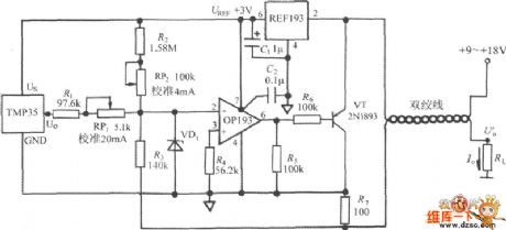
As shown in the figure, it is a 4~20mA temperature transmitter circuit which is composed of TMP35. This circut can change the voltage singal exported by TMP35 into 4~20mA standard current singal, it is used by automatic instruments to control the industry temperature. 4mA is as zero scale interval, 20mA is as full scale alue. REF193 is 3V reference voltage source, OP193 is operational amplifier, RP1、RP2 are calibration full scale alue and zero point's potentiometer, they can be adjusted independently. VD1 adopts Schottky diode, it can avoid OP193 open-loop voltage rising. The power voltage can be chosen between +9~+18V. The expression formula of transmitter's output current is:
(View)
View full Circuit Diagram | Comments | Reading(6919)
VGA Color Display NEC JC-2001VMA Power Supply Circuit
Published:2011/5/9 22:55:00 Author:Sharon | Keyword: VGA, Color Display, Power Supply
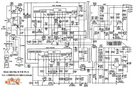
VGA Color Display NEC JC-2001VMA Power Supply Circuit is shown below:
(View)
View full Circuit Diagram | Comments | Reading(623)
Electric automatic check door circuit diagram
Published:2011/5/9 21:26:00 Author:Nicole | Keyword: electric, check door
It is a electric automatic check door circuit diagram, it is fixed a PTC thermal resistor component on the electric check door, this control system is composed of bimetallic strip, electrical heating coil, choke valve relay. When it is lower than the set point of temperature, the choke valve is closed by bimetallic strip, then the starter begins to work, the choke valve relya contact is closed by the voltage of voltage adjuster L terminal, the current flows electrical heating coil, the temperature of bimetallic strip rises, after the temperature rising, the choke valve opens slowly. When the bimetallic strip is heated enough, choke valve opens fully, it uses thermal resistor to control the current of electrical heating coil.
(View)
View full Circuit Diagram | Comments | Reading(1319)
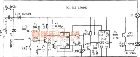
CD4013 feather-touch time delay switch circuit
Published:2011/5/10 1:52:00 Author:chopper | Keyword: feather-touch, time delay switch
View full Circuit Diagram | Comments | Reading(2090)
Transmitter Circuit
Published:2011/5/10 1:05:00 Author:Sharon | Keyword: Transmitter
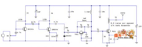
Transmitter Circuit is shown below:
(View)
View full Circuit Diagram | Comments | Reading(949)
Reed switch current sensor circuit diagram
Published:2011/5/9 21:44:00 Author:Nicole | Keyword: reed switch, current, sensor
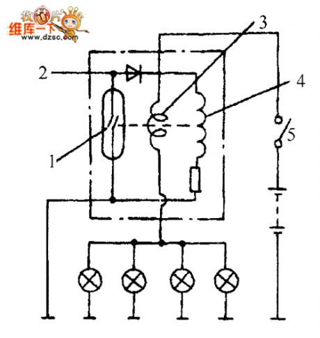
As shown in the figure, it is a current sensor circuit, when the switch closes, if all the bukbs work normally, it has rated current in current coil, then under the action of magnetic force which is produced by coil, the reed switch closes, if the bulb wire is breaking, the related current reduces, the magnetic force drops off, it makes reed switch cut off, then it will alarm.
(View)
View full Circuit Diagram | Comments | Reading(3296)
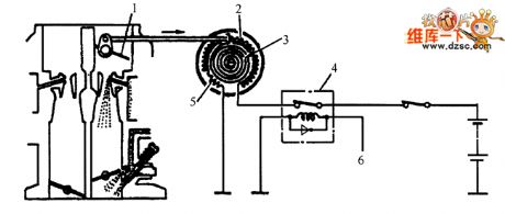
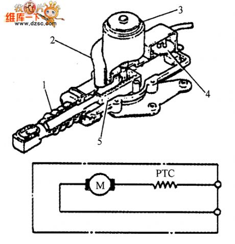
The structure and circuit diagram of gate control motor
Published:2011/5/9 21:09:00 Author:Nicole | Keyword: gate control, motor, structure
View full Circuit Diagram | Comments | Reading(577)
Very simple low pass filter(integrator) circuit diagram
Published:2011/5/10 1:45:00 Author:Nicole | Keyword: low pass filter, integratorv
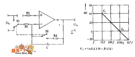
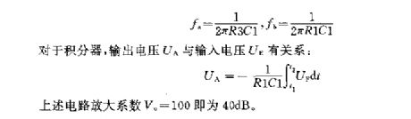
It is a simple low pass filter, it also can be used as integrator, when it is used as integrator, the switch S1 is connected to input terminal, and S2 is cut off. When it is used as low pass filter, R3 is connected to circuit, then the voltage amplification is Vo=R3/R1, the singal source internal resistance Ri << R1, and R2's value should be equal to the parallel equivalent value of R3 and R1.
The frequency value is determined by the below formula:
(View)
View full Circuit Diagram | Comments | Reading(834)
One dimension PSD equivalent circuit diagram
Published:2011/5/10 2:52:00 Author:Nicole | Keyword: one dimension, PSD equivalent

View full Circuit Diagram | Comments | Reading(646)
Ordinary filter circuit diagram
Published:2011/5/10 2:43:00 Author:Nicole | Keyword: filter
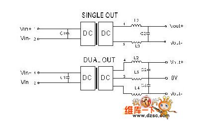
In the ripple and noise susceptible circuit, it can add a filter to DC/DC input terminal and output terminal, it can reduce the ripple and noise. It can absorb the peak voltage of input terminal by importing additional capacitance, it also can store energy and keep voltage stable, The output ripple can be reduced by exporting additional capacitance, the capacitance value too large or ESR too low will easily cause start up problems; if it requires very low ripple, it can adopt LC filtering network or use power module with low ripple output.
(View)
View full Circuit Diagram | Comments | Reading(1292)
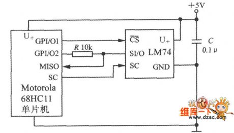
68HC11 single chip microcomputer circuit diagram composed of intelligent temperature sensor
Published:2011/5/10 3:25:00 Author:Nicole | Keyword: single chip microcomputer, intelligent temperature sensor
View full Circuit Diagram | Comments | Reading(1951)
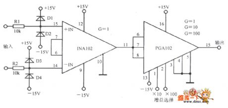
Programmable instrument amplifier circuit diagram based on a gain
Published:2011/5/10 3:23:00 Author:Nicole | Keyword: Programmable instrument, amplifier, gain
View full Circuit Diagram | Comments | Reading(545)
5-channel temperature measurement and control system circuit diagram
Published:2011/5/10 2:48:00 Author:Nicole | Keyword: temperature, measurement and control system

View full Circuit Diagram | Comments | Reading(843)
| Pages:1915/2234 At 2019011902190319041905190619071908190919101911191219131914191519161917191819191920Under 20 |
Circuit Categories
power supply circuit
Amplifier Circuit
Basic Circuit
LED and Light Circuit
Sensor Circuit
Signal Processing
Electrical Equipment Circuit
Control Circuit
Remote Control Circuit
A/D-D/A Converter Circuit
Audio Circuit
Measuring and Test Circuit
Communication Circuit
Computer-Related Circuit
555 Circuit
Automotive Circuit
Repairing Circuit