
Circuit Diagram
Index 1903
op amp type BBE processor circuit
Published:2011/5/8 6:49:00 Author:TaoXi | Keyword: op amp, BBE, processor
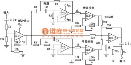
The BBE high resolution sound processor outputs the high, medium and low frequency signals of the signal source through the high-pass filter, band-pass filter, low-pass filter, and respectively controls the gain then mixes them to highlight the high, medium and low frequency signals' content information, so this processor achieves the effects of extending the frequency response and clarity. The op amp type BBE processor circuit is as shown. The input signal is amplified by IC1-1, then part of the high frequency input signal is intercepted by the high-pass filter, part of the low frequency input signal is intercepted by the low-pass filter, the intercepted high & low frequency signals are amplified by the IC2-2, IC2-1 and then they mix with the unprocessed signal in the adder to enhance the high and low frequency signals and beautify the sound.
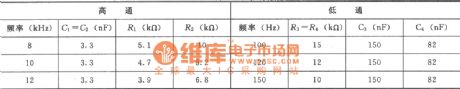
The component values of this circuit is as shown in this table.
(View)
View full Circuit Diagram | Comments | Reading(4345)
CDO031AM-16bitD/A converter integrated circuit
Published:2011/5/10 1:00:00 Author: | Keyword: converter


CDO031AM is a 16bitD / A converter integrated circuit.It's used widely in changhong remarkable series of fine,the rear movement color TV.
1. Features
CDO031AM integrated circuit's interior is mainly composed of digital convergence correction circuit RV,digital convergence correction circuit GV,digital convergence correction circuit BV,analog BH correction circuit,analog RH correction circuit,analog GH correction circuit,clock circuit,reference voltage circuit, DAC circuit, DAC Central power supply circuit, the digital power supply circuit, analog power circuits and other features supporting circuit.
2. pin functions and data
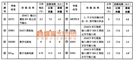
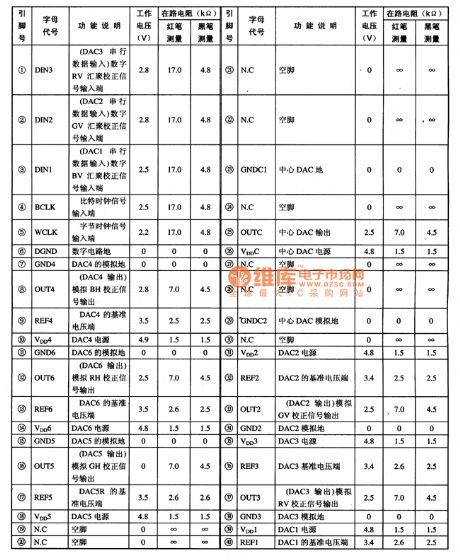
CDO031AM integrated circuit uses 48-pin DIP package structure.The pin function and data are listed in table 1.
Table 1 CDO031AM integrated circuit's pin function and data
Tip: CDO031AM integrated circuit has more supply pins, different circuit supply the power introduced by different pin,.when repairing the circuit,we should test the corresponding power supply pins. (View)
View full Circuit Diagram | Comments | Reading(548)
BU5814FT1 monolithic remote control transmitter integrated circuit
Published:2011/5/10 1:16:00 Author:Fiona | Keyword: monolithic remote control transmitter

BU5814FT1 is a monolithic remote control transmitter integrated circuit.It's widely used in various remote control systems, such as DVD players, televisions, audio equipment.
1.Features
BU5814FT1 contains the keys scan pulse generator integrated circuit, the remote control command encoder, emission signal buffer amplifier circuit, transmitting the signal buffer amplifier circuit, test circuit, the user code setting circuit, and other ancillary circuit.
2.pin functions and data
BU5814FT1 integrated circuit uses 22-pin dual in-line package.The pin functions and data are shown in Table 1.
Table 1 BU5814FT1 integrated circuit's pin functions and data
3.Typical application circuit
The infrared remote control transmitter's typical application circuit which is posed by the BU5814FT1 integrated circuit is shown in Figure 1.
Figure 1 the typical application circuit of the BU5814FT1 integrated circuit
Tip: to determine whether the remote control transmitter IC is damaged, it's available to use multimeter to test the potential of BU5814FT1 (19) feet.Whether the potential has a small jump. If has,it is illustrated that there has coded pulse signal output from the output,the integrated circuit is working properly;on the contrary,the integrated circuit is damaged,it need to replace a new integrated circuit. (View)
View full Circuit Diagram | Comments | Reading(1210)
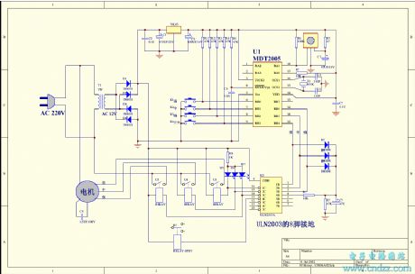
Littleswan XPB30-5 washing machine principle circuit
Published:2011/5/11 2:22:00 Author:Christina | Keyword: Littleswan, washing machine, principle circuit
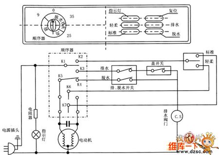
The Littleswan XPB30-5 washing machine principle circuit is as shown:
(View)
View full Circuit Diagram | Comments | Reading(2441)
FSK 315MHz transmitter circuit
Published:2011/5/9 5:07:00 Author:John | Keyword: transmitter circuit
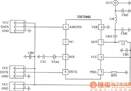
TH72001 is a single-chip transmitter chip, designed with a standard line with EN 300220 and some similar standards. It can be used in keyless entry systems, remote telemetry systems, data communications systems and security and other systems. The main technical characteristics are as follows: • Operating frequency is 290 ~ 350 MHz; • Single-ended RF output; • FSK modulation; • FSK modulates through crystal pulling and FSK modulates at rate of DC ~ 40 Kb / s;• Power supply is l .9 ~ 5.5 V; • Operating current is 3.5 ~ 10.7mA and standby current is 0.1μA; • Output power is adjustable within -15 ~ +6 dBm. (View)
View full Circuit Diagram | Comments | Reading(2043)
electricity testing pencil circuit
Published:2011/5/11 2:22:00 Author:Christina | Keyword: electricity, testing pencil
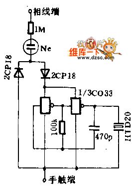
When you are testing the electricity, the weak current gets through the resistor and neon tube, and makes the neon tube toturn on, the current also makes the oscillation circuit (compose of the CMOS IC) to start oscillating, and makes the piezoelectric ceramic to send out voice.
(View)
View full Circuit Diagram | Comments | Reading(765)
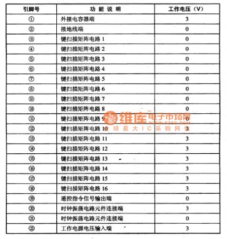
BU-3762AF monolithic remote control transmitter integrated circuit
Published:2011/5/10 1:17:00 Author:Fiona | Keyword: monolithic remote control transmitter
BU-3762AF is a monolithic remote control transmitter integrated circuit.It’s widely used in various remote control systems, such as televisions, audio equipment, DVD players and so on.
1. Features
BU-3762AF integrated circuit includes scan keys pulse generator, telecommand encoder, clock oscillation circuit, transmit signal pre-amplifier circuit, test circuit, and other ancillary circuit.
2. pin functions and data
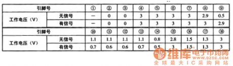
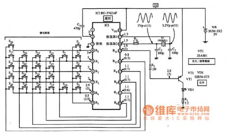
BU-3762AF integrated circuit uses 18-pin dual in-line package.The main pin function as follows:② feet: reset control signal input, high reset.④ - (14) feet: constitute the keyboard matrix circuit used for manual operation.(15) feet: remote control command signal output, the output signal promotes the infrared emitting diodes infrared light after being amplified by the driver tube VT1 (17), (16) feet: the side external components of clock oscillation circuit.(18) feet : the supply voltage input.the working parameters of BU-3762AF integrated circuit is listed in Table 1.
Table 1 the working parameters of BU-3762AF integrated circuit
3. Typical application circuit
The typical application of the remote control circuit consisting of BU-3762AF integrated circuitisshown in Figure 1.
Figure 1 typical application of the remote control circuit consisting of BU-3762AF integrated circuit
(View)
View full Circuit Diagram | Comments | Reading(850)
universal single and dual power supply quad op-amp circuit
Published:2011/5/9 2:00:00 Author:John | Keyword: quad op-amp

LM324 is a high-gain quad op-amp, which has four modules inside. Both single power and dual power supply are available for operating. It can work under a rather wide range of working power supply voltage. A very small Supply Current is needed. Input bias current is with temperature compensation performance, so no external frequency compensation components are needed. Amplifier LM324 can be applied in conversion amplifiers, DC gain units and universal op-amp circuits for many applications. And it also can be used directly as interface circuit for a variety of logic circuits and other low-pressure systems. Direct models or substitutions can be LMl24、CFl24MD、CF224LD、CFl24MJ、CF224LJ、CF324CJ and CF324CP and so on. The circuit shown above is the situation that LM324 is used as a dual-threshold voltage comparator.
(View)
View full Circuit Diagram | Comments | Reading(1183)
The light comparison device circuit of light comparison standard
Published:2011/5/11 2:18:00 Author:Christina | Keyword: light comparison standard, light comparison

In order to adjust the brightness of two light sources for the same, you can use this circuit as the light comparison standard. PC1 and PC2 are the solar cells. At the beginning, if you want to make the electric bridge in balance, the two solar cellsare irradiated by the same light source, and it uses the R to adjust the zero-point to make the reading points to the center of the zero meter.
(View)
View full Circuit Diagram | Comments | Reading(535)
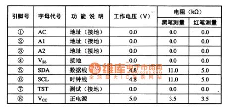
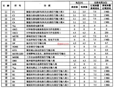
C271AD single-chip micro-computer communication integrated circuit diagram
Published:2011/5/10 1:16:00 Author:Fiona | Keyword: single-chip micro-computer communication
C271AD is a single-chip micro-computer communication integrated circuit. It's widely used in wireless phones and other communication devices.
1. Features
C271AD integrated circuit's in-circuit is mainlyformed by the key position pulse generator circuit, the key instruction encoding circuit, the clock oscillation circuit, two-tone and pulse signal processing circuit,pulse dialing rate intermittent selection circuit,dial-up mode selection circuit, hands-free control circuit, squelch Control circuit etc.
2. pin functions and data
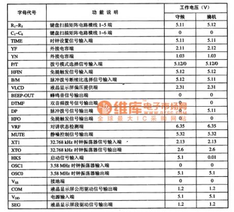
C271AD related pin letter designations, function descriptions and data are listed in Table 1.
Table 1 C271AD integrated circuit's pin functions and data
3. Typical application circuit
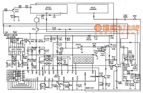
the control system typical application circuit which isformed by the C271AD integrated circuit is shown in Figure 1.
Figure 1 The typical application circuit of the C271AD integrated circuit
(View)
View full Circuit Diagram | Comments | Reading(1516)
TA869OAN, TA869lAN single chip dual-mode color TV circuit
Published:2011/5/10 2:25:00 Author:TaoXi | Keyword: single chip, dual-mode, color TV
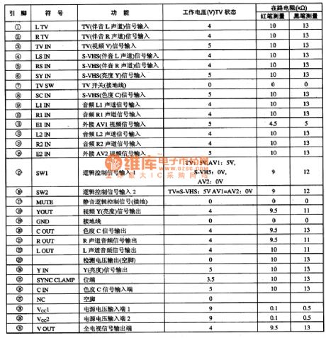
The TA869OAN and TA869lAN are designed as the single chip dual-mode color TV circuit that is produced by the TOSHIBA company, and they can be used in the domestic and imported color TVs.
1.Features
The TA869OAN and TA869lAN has the image IF function circuit, the sound IF function circuit, the video function circuit, the color function circuit and the line field small signal circuit.
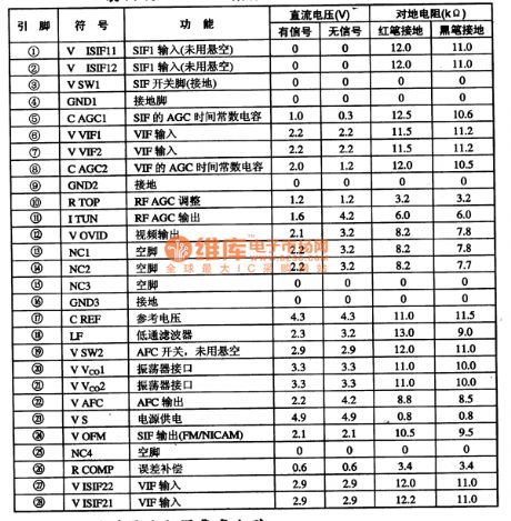
2.Pin functions and data
The difference between TA869OAN and TA869lAN is the reverse and positive of the RF AGC control, the manifold in-circuit block diagram, the pin functions and data is as shown in figure 1.
Table 1 The pin functions and data of the TA872OAN (View)
View full Circuit Diagram | Comments | Reading(836)
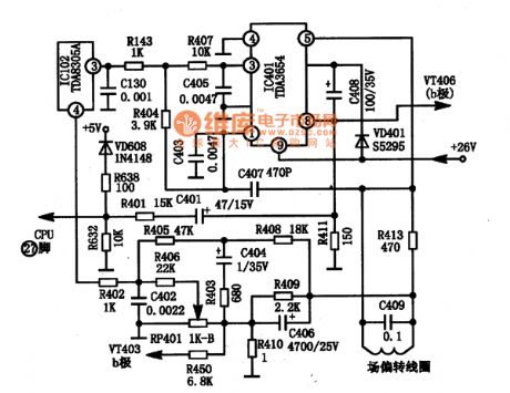
TDA4660, TDA4660V2 integrated block internal box circuits
Published:2011/5/9 3:06:00 Author:TaoXi | Keyword: integrated block, internal box
2.Pin functions and data
The TDA4472 is in the 28-pin dual in-line package, the pin functions and data is as shown in table 10.
Table 10 The pin functions and data of the TDA4472 circuit
TDA4601--Thick-film switch power supply integrated circuit
The TDA4601 is designed as the thick-film switch power supply integrated circuit that is produced by the PHILIPS company, and it can be used in various types of large screen color TV and computer monitor switch power supply circuit.
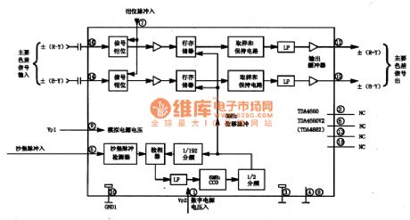
TDA4660, TDA4660V2--The baseband delay IC
The TDA4660 and TDA4660V2 are designed as the baseband delay IC which is produced by the PHILIPS company, and it can be used in variety of multi-system color TVs.
1.Features
The TDA4660 and TDA4660V2 can process the positive and negative color difference input signals, and clamp the fused AC input signal ±(R-Y) and ±(B-Y); and lock the 3MHz internal clock signal by the sand castle pulse (64us cycle), the 3MHz internal clock signal is from the internal 6MHz Vcc divided-frequency. The integrated block internal box circuit is as shown in figure 10.
(View)
View full Circuit Diagram | Comments | Reading(1265)
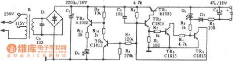
The Circuit Diagram of TDA2822 and its main electrical parameters
Published:2011/5/10 2:27:00 Author:TaoXi | Keyword: Circuit Diagram, main electrical parameters
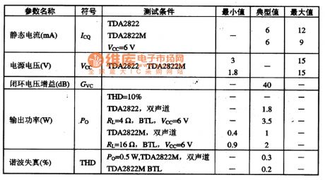
3.TDA2822 main electrical parameters
The main electrical parameters of the TDA2822 and TDA2822M has some points of differences. The main electrical parameters of the TDA2822 and TDA2822M are as shown in table 7.
Table 7 The main electrical parameters of the TDA2822 and TDA2822M
4. Signal process
The signal gets into the IC by TDA2822M's pin-6 and pin-7, and the signal is amplified by the power amplifier then output by pin1 and pin3 to promote the speaker or headphone.
In this circuit, the Joubert network of the left and right channel power amplifier is composed of the C5, R3 and R4, C6.
5.Troubleshooting tips
If the left and right channels are silent, and the power supply between the TDA2822M's pin2 and the ground is normal, then it is mostly the TDA2822M's own fault.
(View)
View full Circuit Diagram | Comments | Reading(3032)
CD4060 Timing Ni-Cd battery charger circuit
Published:2011/5/9 1:58:00 Author:John | Keyword: Timing Ni-Cd battery charger
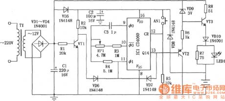
This circuit is a timing charger. The charging time can be adjusted from 5 to 25 hours. If power failure occurs in the charging process, the circuit has a function of cumulative timing. The circuit is available for recharging a 5 nickel-cadmium battery. (View)
View full Circuit Diagram | Comments | Reading(4682)
CAT24C16F electric erasable and programmable read only memory integrated circuit diagram
Published:2011/5/10 1:16:00 Author:Fiona | Keyword: electric erasable, programmable read only memory
(View)
View full Circuit Diagram | Comments | Reading(536)
AC-209H battery charger circuit
Published:2011/5/9 1:59:00 Author:John | Keyword: battery charger
The diagram shown above is the AC-209H battery charger circuit. (View)
View full Circuit Diagram | Comments | Reading(997)
High-voltage Linear SCR Amplification Circuit
Published:2011/5/10 4:21:00 Author:Sharon | Keyword: High-voltage, Linear, SCR, Amplification
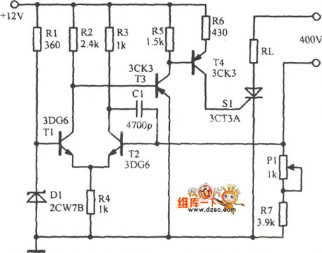
High-voltage Linear SCR Amplification Circuit is shown in below figure:
(View)
View full Circuit Diagram | Comments | Reading(866)
universal single-supply dual operational amplifier circuit
Published:2011/5/10 23:07:00 Author:John | Keyword: single-supply, dual operational amplifier
(View)
View full Circuit Diagram | Comments | Reading(884)
HM9114A-The Intergrated Circuit of Microcomputer Dialing
Published:2011/5/11 2:05:00 Author:Borg | Keyword: Intergrated Circuit, Micro Computer
HM9114A is an intergrated circuit of microcomputer dialing,which is widely used in all kinds of phones.
HM9114A is encapsulated in dual-line ways with 22-lead, whose pin functions and data are listed in Table 1-1.
Table 1-1 pin functions and data of HM9114A (View)
View full Circuit Diagram | Comments | Reading(658)
HM9113A-The Intergrated Circuit of Microcomputer Dialing
Published:2011/5/11 2:09:00 Author:Borg | Keyword: Intergrated Circuit, Microcomputer Dialing

Pin functions and dataof HM9113 are listed in Table 1-1.
Table 1-1 pin functions and data of HM9114A (View)
View full Circuit Diagram | Comments | Reading(616)
| Pages:1903/2234 At 2019011902190319041905190619071908190919101911191219131914191519161917191819191920Under 20 |
Circuit Categories
power supply circuit
Amplifier Circuit
Basic Circuit
LED and Light Circuit
Sensor Circuit
Signal Processing
Electrical Equipment Circuit
Control Circuit
Remote Control Circuit
A/D-D/A Converter Circuit
Audio Circuit
Measuring and Test Circuit
Communication Circuit
Computer-Related Circuit
555 Circuit
Automotive Circuit
Repairing Circuit