
Circuit Diagram
Index 1905
Bicyle Bell Circuit (1)
Published:2011/5/9 3:30:00 Author:Robert | Keyword: Bicyle, Bell
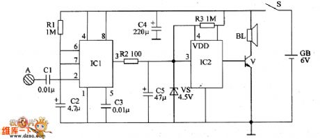
The bicycle bell circuit intruduced in this example can give the voice tone: Please make way, thank you after the touching by hands.The circuit's working principle is shown below.This bycycle bell circuit is made up by monostable trigger and voice circuit which is shown in the picture below.The monostable trigger circuit is made up by time-reference integrated circuit IC1, touching electrode A, capacitors C1~C3 and resistance R1.The voice circuit is made up by voice integrated circuit IC2, zener diode VS, resistance R2, R3, audio amplification transistor V and speaker BL.When the power switch S is connected, the monostable trigger is in stable mode. IC1's 3 foot outputs low voltage level to make the voice integrated circuit IC2's 3 foot and 4 foot be low voltage level. The transistor V is disconnected and the speaker B has no sound.When the touching electrode A is touched by hands, the human body sensing signal is transmitted to IC1's 2 foot through the capacitor C1 to trigger IC1 to change the stable mode to transient mode. Its 3 foot outputs high voltage level to make the IC2's 3 foot and 4 foot turn to be high voltage level. The transistor V is connected and speaker BL would play the voice tone.Each time the touching electrode A is touched, IC1's invert transient time would be 5s and the voice circuit would play twice the voice tone.
(View)
View full Circuit Diagram | Comments | Reading(947)
Sitting Posture Reminder Device Circuit (2)
Published:2011/5/11 1:27:00 Author:Robert | Keyword: Sitting Posture, Reminder
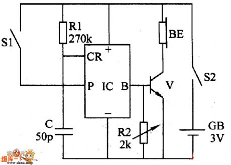
The sitting posture reminder device introduced in this example, should be hung on the user's ears or be installed on the hats when using. When the user's upper body or head has a big front-lean angle it would give out the voice reminder tone: Please note the myopia!Sit upright quickly! or Please note the sitting posture! . This device can not only be used for the office staffs and students' sitting posture correction, myopia protection, but also can be used as the sleep reminder for the motor vehicle drivers.The circuit's working principle is shown below.This sitting posture reminder is made up by the mercury switch (as front-lean angle sensor) S1, resistance R1, R2, capacitor C, voice integrated circuit IC, transistor V, earphone BE, power switch S2 and battery GB which is shown in the picture below.In normal time (the user's sitting posture is correct), the mercury switch S1 is disconnected, IC do not work, BE has not sound. When the user's head has a certain front-lean angle the S1 is connected to trigger IC to work. It outputs the voice electrical signal which is amplified by V and then this signal drives BL to play the voice reminder tone.The angle which trigger the alarm sound can be changed by adjusting S1's position.The tone played by BE can be adjusted by changing R2's value.
(View)
View full Circuit Diagram | Comments | Reading(853)
TC9153P electronic volume control IC
Published:2011/4/26 22:34:00 Author:TaoXi | Keyword: electronic volume, control IC
The TC9153P is designed as one kind of C(2)MOS Tsz volume control integrated circuit, it can be used in the audio equipment to control the electronic volume .
1.TC9153P circuit block diagram and pin functions
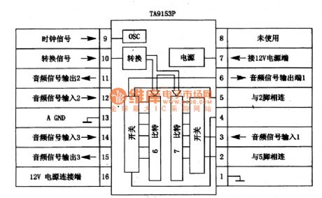
The TC9153P is composed of the clock oscillation circuit, conversion circuit, electronic switch circuit, 6-bit and 7-bit circuit.etc, the TC9153P circuit block diagram and pin functions is as shown:
Table 1. The TC9153P circuit block diagram and pin functions.
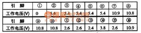
The TC9153P integrated circuit is in the 16-pin dual in-line package, the operating voltage of every pin is as shown in table 1.
Table 1. The operating voltage of TC9153P.
2.TC9153P main electrical parameters
The TC9153P IC supply voltage range is 5 to 12V; in the condition of Vcc=l2V, Vss=0V, Ta=25 ℃, the electrical parameters are as shown in table 1. Both of the IC's positive and negative (+,-) or single power supplier can supply power: as a result of the C (2) COM structure, this device has wide operating voltage range and low current consumption (Vcc=5-12V,IDD=1-3mA).
3.TC9153P typical application crcuit
The TC9153P can be used with the microprocessor TC915OP, so the TC9153P and TC915OP has the same typical application circuit.
4.The circuit working process
The TC9153P controls the attenuation by the internal oscillator and the increase / decrease pin, control range is 0 to 68dB and divide into 32 levels (per 2dB).
Table2. TC9153Pmainelectricalparameters
5.Fault tips
If there is little or no volume, you can use a 10μF capacitance to link the pin-3 and pin-6 of TC9153P, if the voice return to normal, means the TC9153P has interal damage. (View)
View full Circuit Diagram | Comments | Reading(1368)
Sitting Posture Reminder Device Circuit (1)
Published:2011/5/11 1:29:00 Author:Robert | Keyword: Sitting Posture, Reminder

When the primary and secondary students are reading or writing, if their sitting posture is not correct for a long time, it would easily affect their vision and physical health. The sitting posture reminder device introduced in this example can remind the users when their reading or writing posture is not correct by giving out the sound: DD or voice reminder tone. So it can remind the user to note their posture and fix it.The circuit's working principle is shown below.This sitting posture reminder device circuit is made up by electronic switch circuit GB, alarm circuit and power circuit which is shown in the picture below.The electronic switch circuit is made up by glass shell mercury switch S2, transistor V1, V2 and resistance R1~R3.The power circuit is made up by power GB and power switch S1.When he power switch S1 is connected, the power GB would be supply the whole circuit with the working voltage.When the user's reading or writing posture is correct, the mercury switch S2 would be disconnected and the transistor V1 and V2 are all disconnected. The integrated circuit IC is not working and BL has no sound.When the user's sitting posture is front-lean (near the desktop), the S2 would be connected and V1 and V2 are al connected. V2's emitter output high voltage level to the IC's TRIG port to trigger the IC to work. Then its output port (OUT) would output the audio signal, which is amplified by V3, to drive the speaker to give out the DD' alarm sound or play the voice reminder tone: Please note myopia! Sit upright quickly! .
(View)
View full Circuit Diagram | Comments | Reading(808)
Household gas alarm circuit
Published:2011/5/8 6:49:00 Author:TaoXi | Keyword: Household, gas, alarm
The Household gas alarm circuit is as shown:
(View)
View full Circuit Diagram | Comments | Reading(579)
TA8851CN I2C bus control switch IC
Published:2011/5/9 2:58:00 Author:TaoXi | Keyword: I2C, bus control switch
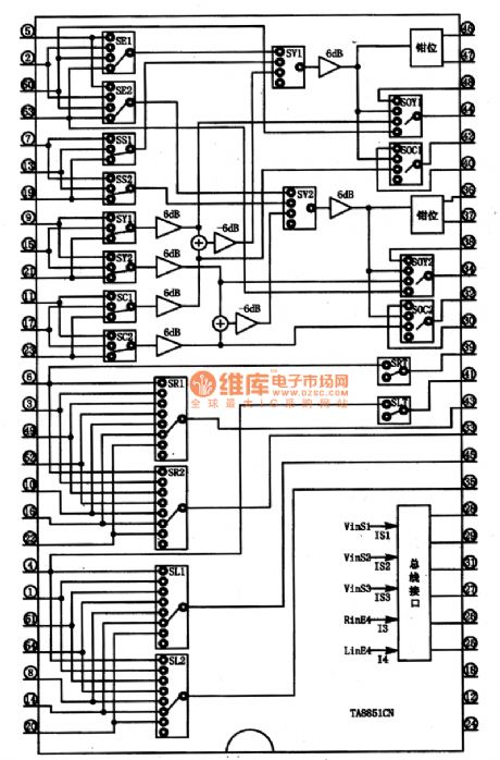
The TA8851CN is designed as one kind of I2C bus control switch IC that is produced by the TOSHIBA company, and it can be used in video, audio, multi-channel signal switching and control applications.
1.Features
The TA8851CN has the multi-channel electronic switch circuit, the I2C bus interface circuit and the mute control circuit.etc. The block diagram of the circuit is as shown in figure 1.
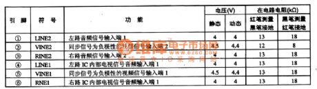
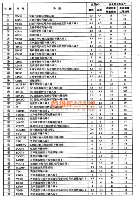
2.Pin functions and data
The TA8851/CN is in the 54-pin package, and it can be used in large screen color TV. As the TV/AV/S switch, the pin functions and data of this circuit is as shown in table 1.
Tip: If you want to check the fault leaves, you can use the oscilloscope to check if the different signal's input port and corresponding output port both have thesignals, so you can ensure if the electronic switch is damaged.
Figure 1 The in-circuit block diagram of the TA8851N
Table 1 The pin functions and data of the TA8851CN (View)
View full Circuit Diagram | Comments | Reading(1199)
Voice Control Music Doorbell Circuit
Published:2011/5/11 1:30:00 Author:Robert | Keyword: Voice Control, Music, Doorbell

This voice control music doorbell circuit uses two integrated circuit, a 3V battery to supply. Its static consumption current is about 100uA which would be tens of mA while playing the sound.The circuit's working principle is below:The circuit is shown in the picture below. NE555 is working in monostable mode. The trigger-port 2 foot's DC voltage is set a little higher than one third of Vdd. When there is door-knocking sound or other sound, TC would generate voltage to trigger NE555's 3 foot to output high voltage which has been inverted. Then it would trigger the music integrated circuit. So after the buffering in 9013 the music signal would drive the speaker to play music. When static, NE555's consumption current is just tens of mA, and other components' consumption current is just several uA.The debug method is shown below:This circuit is easily to install and needn't debugging in normal conditions. If the components are all good, the circuit would work by connecting these components. If the user wants to increase the sensitivity of voice control, he can adjust the partial voltage of the NE555's 2 foot and by changing this voltage it could achieve the goal. The nearer 2 foot's voltage is to the one third of Vdd, the more sensitivity the voice control has. But, if the sensitivity is too high, well the circuit would work if there is a little sound. Also the NE555's 2 foot's voltage can be a little various in different time and temperature which may cause the circuit going wrong or disable.
(View)
View full Circuit Diagram | Comments | Reading(1443)
Shanghai GM Chevrolet Sail Car Safety Airbag Circuit
Published:2011/5/10 21:57:00 Author:Robert | Keyword: Shanghai GM, Chevrolet, Sail, Safety Airbag
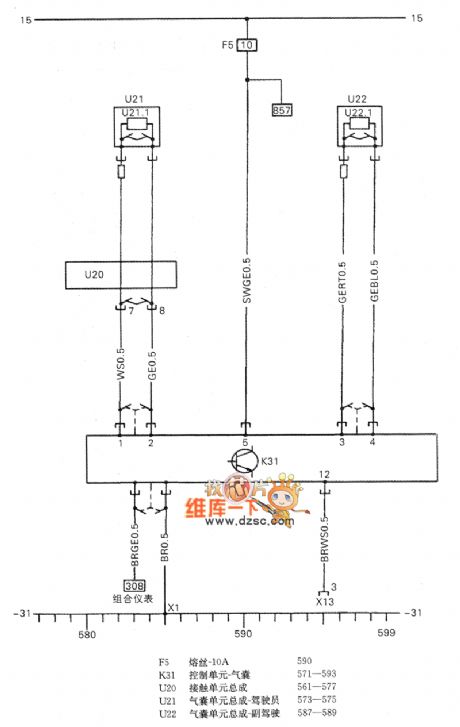
The Shanghai GM Chevrolet Sail Car Safety Airbag Circuit is shown below.
F5 fuse-10A 590
K31 Control unit-airbag 571-593
U20 contactor unit 561-577
U21 airbag unit-pilot 573-575
U22 airbag unit-copilot 587-589
(View)
View full Circuit Diagram | Comments | Reading(982)
The basic connection circuit of INAL25 signal and power supply
Published:2011/5/8 18:44:00 Author:Christina | Keyword: basic connection, signal, supply
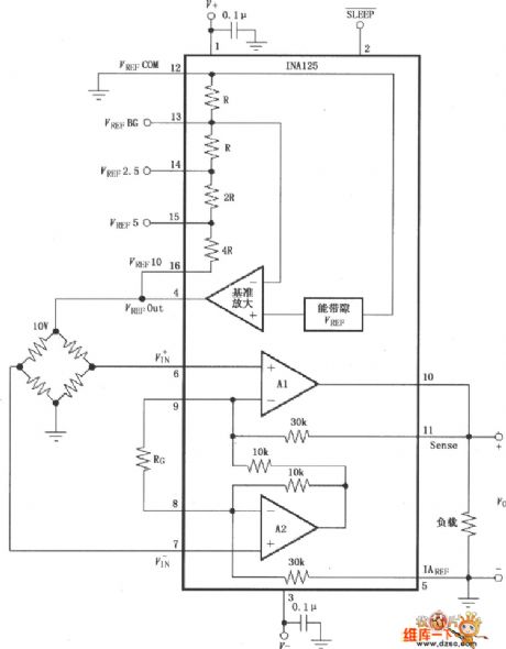
The The basic connection circuit of INAL25 signal and power supply is as shown. In the noise environments or high-impedance power supply applications, the chip power port need to use the capacitor filter, and close to the chip power pin. The output voltage is based on the iaref port standard. You should notice that the standard terminal need to be low resistance connection to ensure the CMRR is high, such as if there is a 12ω series resistance, the CMRR will decrease about 80db(g=4). Gain g=4+60kω/rg, in this formula, 60kω means the total value of the two internal feedback resistors of ina125. The two internal feedback resistors are regulated by the laser, so the selection of external resistor rg has great impact with the gain, you need to use the resistance of good stability and small temperature drift. When the circuit needs to work in the high gain state, the external resistor rg's value is small, you should notice the contact resistance of lead, such as if the socket contact is good.etc, the lead's contact resistance direct results the gain error and affects the stability.
(View)
View full Circuit Diagram | Comments | Reading(641)
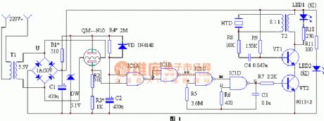
PTC without-water side-thermal mode circuit
Published:2011/5/8 18:43:00 Author:Christina | Keyword: PTC, without-water, side-thermal mode
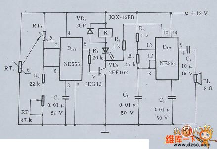
The PTC without-water and over-temperature control side-thermal mode circuit is composed of the detection, control, alarm and other components, the circuit is as shown in figure 1. When there is no water or the water temperature exceeds a set value, RT1's resistance increases and passes to RT2, RT2's resistance also increases after heated, this makes the U1<4V. so ⑤'s output becomes high-level voltage, V conducted and VD2 sends out the red indication, relay K's normally closed contact-point cuts off, and switches off the power immediately, at the same time, the alarm works, BL sends out the voice to achieve the dual purposes of alarm and power off.
Figure 1. The PTC without-water and over-temperature control side-thermal mode circuit (View)
View full Circuit Diagram | Comments | Reading(611)
-55℃ to +150℃ digital thermometer circuit
Published:2011/5/10 22:31:00 Author:Christina | Keyword: digital, thermometer circuit
This circuit is composed of the new semiconductor temperature sensor IC two-terminal device SL590 and the 3-bit half-digital voltage panel meters 5GM14433, and it can measure the -55 to +150 ℃ temperature range. The temperature is changed into the current signal by SL590, and the current signal is changed into the voltage signal (corresponds to the Celsius temperature) by the operational amplifier, then the voltage signal gets into the 5GM14433's VX input port and becomes the digital signal that is desplayed by the LED.
The power supply is the AC, DC-style. AC power supply has 220V voltage, or you can use four 1.5V batteries as the power.
(View)
View full Circuit Diagram | Comments | Reading(481)
Digital long time delay circuit
Published:2011/5/10 22:31:00 Author:Christina | Keyword: Digital, long time delay
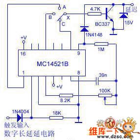
General long delay circuit usually needs the electrolytic capacitors or high impedance circuits. Theses delay circuit has the poor stability and low delay accuracy.
Here is one kind of digital long time delay circuit, it completely abandons the large electrolytic capacitors and high impedance circuits, and it has high delay accuracy.
The core component of this circuit is the MC14521B, it is a 24-stage frequency circuit and has the inverter. If you connect the trigger input port to the ground or do not add any signals, the circuit will get into the delay state, the delay time is controlled by the range switch X and the 100KΩ potentiometer.
If we connect X with point A, the delay time is 1 minute 40 seconds to 18 minutes and 30 seconds. The delay time is adjusted by the 100KΩ potentiometer. If you need the longer delay time, you can use the large capacitor instead of the 39nF capacitor. At this time, the delay time will be more than one week.
With the reliable and stable delay, we suggest you to use the 6 to 15V power supply. The prototype's voltage is 12V. (View)
View full Circuit Diagram | Comments | Reading(1456)
Crystal Oscillator Principle Circuit
Published:2011/5/10 3:56:00 Author:Sharon | Keyword: Crystal Oscillator
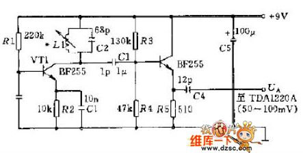
Figure shows a simple oscillator which can be used in receiver. Output Oscillation signal can be connected to operational amplifier TDA1220A pin 1 (the amplitude of the output voltage UA is about 50 ~ 100mV). (View)
View full Circuit Diagram | Comments | Reading(1454)
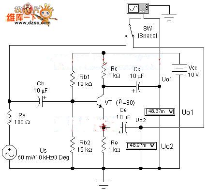
Pressure-separation Negative Feedback Bias Current Amplifying Experiment Circuit
Published:2011/5/10 3:42:00 Author:Sharon | Keyword: Pressure-separation, Negative Feedback, Bias, Amplifying
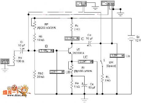

First, demonstration contents1. The composition of amplifier circuit and functions of its components. 2. Quiescent point set, and demonstration of waveform distortion. 3. Dynamic analysis of amplifying circuit.
Second,demonstrative circuit
Figure 1 Pressure-separation negative feedback bias current amplifying experiment circuit
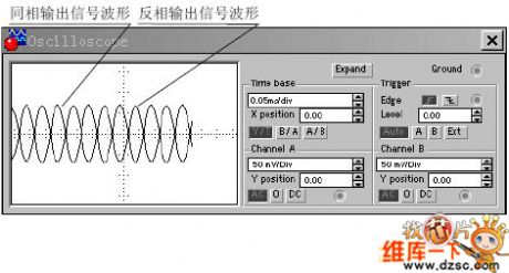
Third, features demonstration
Figure 2 Applying oscilloscope display box showing the input and output signal waveform and phase relationship (View)
View full Circuit Diagram | Comments | Reading(640)
Phase wave-detector circuit
Published:2011/5/10 22:32:00 Author:Christina | Keyword: Phase, wave-detector
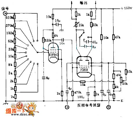
The IR system balance full-wave phase wave-detector is as shown, the RCA7360 is the beam deflection tube, this deflection tube has two deflectors to switch the electron beam from one electrode to another electrode. The conversion function of the deflector is controlled by the reference waveform which is synchronous with the into signal. If you connect a capacitor (8μF or 40μF) to the output port, and charge it with two half-cycle, you can get the doubling of the input value's standard.
(View)
View full Circuit Diagram | Comments | Reading(748)
Non-source adjustable constant electronic load circuit
Published:2011/5/10 22:34:00 Author:Christina | Keyword: Non-source, adjustable, constant electronic load
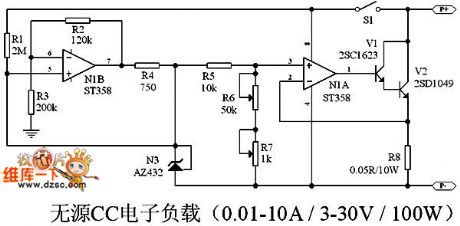
In power supplier industry, the electronic load is the necessary R&D or production equipment of all manufacturers, most electronic loads in the market are very expensive, and they need the power supplier to work. This article supplies one kind of circuit scheme, so that the readers can make the CC mode passive adjustable electronic load by themselves, the input voltage range is 3 to 30V, the input current range is 0.01A to 10A.
The circuit is as shown:
S1 is the load switch, you can disconnect the whole load by S1.
N1B is the quasi-constant current source circuit, the N1B can make the 432 toproduce the1.25V standard and it can also make the current of 432 unchanged even if the input voltage changes. In the CC mode, R8 is the current sampling resistor to feedback the current and make the load current constant. Resistance R6 is the coarse adjustment resistor, resistance R7 is the fine adjustment resistor. (View)
View full Circuit Diagram | Comments | Reading(8301)
Phase Amplifier Analysis Experiment Circuit
Published:2011/5/10 3:46:00 Author:Sharon | Keyword: Phase Amplifier
First, demonstrationContent 1. The composition of phase circuit and static analysis. 2. Dynamic analysis of phase circuit.
Figure 1 Phase amplifier analysis experiment circuit
Second, demonstrative circuit
3. features demonstration
(View)
View full Circuit Diagram | Comments | Reading(573)
NTLTD7900ZR2 Internal Circuit
Published:2011/5/10 2:33:00 Author:Sharon | Keyword: Internal
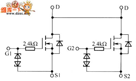
NTLTD7900ZR2'sInternal Circuit is shown below:
(View)
View full Circuit Diagram | Comments | Reading(499)
RF Power Controller Circuit Formed by Monolithic RF Power Measurement System AD8318
Published:2011/5/10 2:22:00 Author:Sharon | Keyword: RF Power Controller, Monolithic, RF Power Measurement
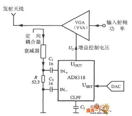
The working principle of the RF power controller is as shown. The control object can be a power amplifier(PA), variable gain amplifier (VGA), variable voltage attenuator (VVA) and so on. When selecting control mode, one should cut USET and UOUT pin from each other. The measured RF power signal is added to the AD8318's input through the directional coupler and attenuator. AD8318's set voltage comes from the D / A converter (DAC). The gain control voltage output from the AD8318's UOUT is used to control the output power of VGA (or VVA).
(View)
View full Circuit Diagram | Comments | Reading(817)
The ultrasonic remote control switch circuit with the infrared remote control mode
Published:2011/5/10 22:36:00 Author:Christina | Keyword: ultrasonic, remote control switch, infrared remote control
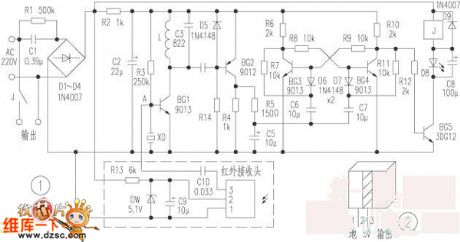
The sub-ultrasonic remote control switch always uses the relay to control the load, and this device has some points of features such as the good load capacity, wide range of applications, low price (6 RMB each), families have a lot of this device. But there is also a weak point: short life of the balloon rubber which can produce the sub-ultrasonic, and this balloon rubber is easy to lose. So we use the TV or VCD's infrared remote controller to control it. The principle and modification method are:
The sub-ultrasonic remote control switching circuit is as shown in the figure, the circuit in the dashed box is the modified circuit, the 220V AC main-voltage is limited and steped down by the C1, the D1~D4 output the DC voltage of about 15V, and this voltage is limited by R2 then supplies to the relay control circuit. XD is the piezoelectric ceramic, the sub-ultrasound is amplified by BG1 and selected by L, C3 and then is amplified by BG2 to trigger the bistable circuit to flip through C6 and C7.
(View)
View full Circuit Diagram | Comments | Reading(897)
| Pages:1905/2234 At 2019011902190319041905190619071908190919101911191219131914191519161917191819191920Under 20 |
Circuit Categories
power supply circuit
Amplifier Circuit
Basic Circuit
LED and Light Circuit
Sensor Circuit
Signal Processing
Electrical Equipment Circuit
Control Circuit
Remote Control Circuit
A/D-D/A Converter Circuit
Audio Circuit
Measuring and Test Circuit
Communication Circuit
Computer-Related Circuit
555 Circuit
Automotive Circuit
Repairing Circuit