
Circuit Diagram
Index 1919
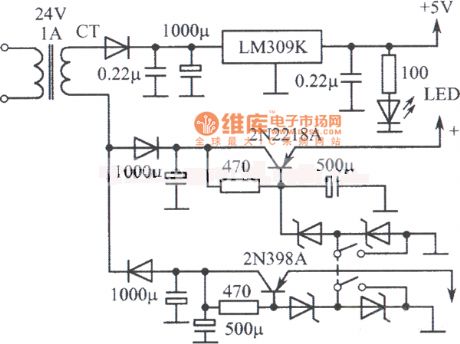
Multiple regulated power supply circuit composed of LM309K
Published:2011/5/9 22:11:00 Author:Rebekka | Keyword: Multiple regulated power supply
View full Circuit Diagram | Comments | Reading(911)
VGA Color Display NEC JC-1404HMN Power Supply Circuit
Published:2011/5/9 22:29:00 Author:Sharon | Keyword: VGA, Color Display, Power Supply
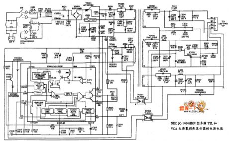
VGA Color Display NEC JC-1404HMN Power Supply Circuit is shown below:
(View)
View full Circuit Diagram | Comments | Reading(583)
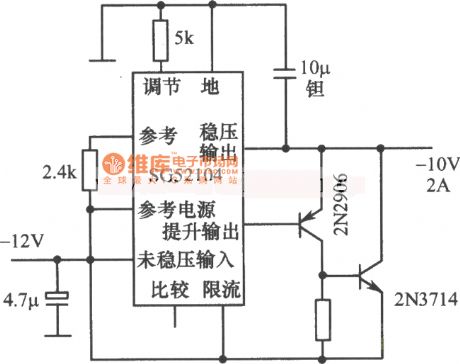
10V 2A regulated power supply circuit composed of SG52104
Published:2011/5/9 22:10:00 Author:Rebekka | Keyword: 10V 2A regulated power supply
View full Circuit Diagram | Comments | Reading(668)
Permeating Optical Interrupter Structure And Circuit
Published:2011/5/9 3:19:00 Author:Sharon | Keyword: Permeating, Optical Interrupter, Structure
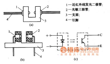
The figure shows the two permeating interrupter structures.Their light-emitting and optical components are separated by a certain interval, and the middle is groove for objects to get through.When the element objects get through, the radiation from light emitting device shines on the optical devices directly, and the optical signal is output as electrical signal. When there are objects inside the interrupter, the radiation of light emitting devices will be blocked, then there is no light from the optical devices, and there is no output signal accordingly.This will identify whether or not there is object in it.Permeating optical interrupter is mainly used for optical control and optical measurement circuits, and can also be used to detect the existence of objects, direction of their movement and speed measurement . (View)
View full Circuit Diagram | Comments | Reading(1592)
13V regulated power supply circuit diagram composed of μ7812
Published:2011/5/9 21:53:00 Author:Rebekka | Keyword: 13V regulated power supply

View full Circuit Diagram | Comments | Reading(869)
CCD Analog Output Signal Processing Circuit
Published:2011/5/7 7:18:00 Author:Joyce | Keyword: CCD, Analog Output, Signal, Processing
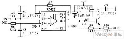
AD623 integrates three op-amps, and it can work with either single power supply or dual power supply.It has relatively high CMRR and extremely low voltage drift. Except a external resistance which is used tocontrol programmable gain, all the other components are integrated in the interior, so as to improve the circuit`s temperature stability and reliability. The analog signal processing circuit of CCD applying AD623 is as shown in the graph.It can send video signals and compensating output to the inverted and non-inverting input of AD623 respectively.Connecting a first-level emitter follower to the output end of AD623 is to enhance the drive ability of the signals . This device can eliminate temperature drift of output signals in circuits using ordinary op-amps and peripheral resistance . (View)
View full Circuit Diagram | Comments | Reading(1328)
High Accuracy 50Hz Time Base Circuit
Published:2011/5/9 5:12:00 Author:Sue | Keyword: High Accuracy, 50Hz, Time Base
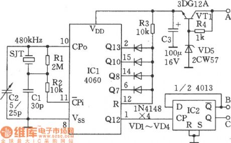
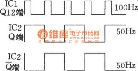
As seen in the figure is the high accuracy 50Hz time base circuit. It consists of two CMOS digital integrated circuits and quartz crystal. This circuit can generate 50Hz time base signal with an accurate frequency and consistent duty ratio. It is simple and easy to make. The figure below is the waveform figure.
(View)
View full Circuit Diagram | Comments | Reading(897)
Keying Oscillator Circuit
Published:2011/5/9 5:10:00 Author:Sue | Keyword: Keying, Oscillator
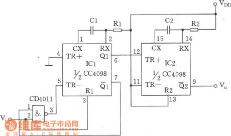
As seen in the figure is keying oscillator circuit composed of monostable trigger CC4098, Four-2 input terminal and NOT gate CC4011. This circuit has a adjustable frequency and duty ratio. It is mainly usd in low frequency signal generator with a low accuracy requirement. (View)
View full Circuit Diagram | Comments | Reading(652)
Discrete Device-composed Power Supply of Changing 5V to ±15V Circuit
Published:2011/5/7 6:19:00 Author:Joyce | Keyword: Discrete Device-composed, Power Supply , of Changing 5V to ±15V
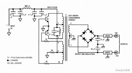
Discrete Device-composed Power Supply of Changing 5V to ±15V Circuit (View)
View full Circuit Diagram | Comments | Reading(1736)
Pocket Digital Timing Hypnotic Massager Circuit Composed of 555
Published:2011/5/9 5:09:00 Author:Sue | Keyword: Pocket, Digital Timing, Hypnotic, Massager
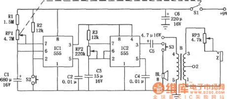
As seen in the figure is the pocket digital timing hypnotic massager circuit composed of 2 555 timers. It can satisfy people's demand on leisure and health. The circuit consists of 3 parts: timer circuit, hypnotic circuit and massager circuit. (View)
View full Circuit Diagram | Comments | Reading(882)
Time-delay Circuit with Watchdog Composed of 555
Published:2011/5/9 5:14:00 Author:Sue | Keyword: Time-delay, Watchdog

Originally this circuit was an electrified time-delay control circuit. The delayed time is decided by R1 and C1. But when watchdog circuit is added, it can be used as observation circuit for certain application systems. (View)
View full Circuit Diagram | Comments | Reading(2141)
MN6030B Remote Control Transmitter Circuit
Published:2011/5/9 1:13:00 Author:Sharon | Keyword: Remote Control Transmitter
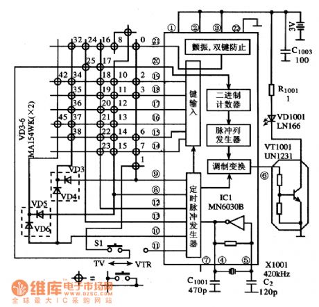
MN6030B is Panasonic's remote control transmitter IC.It'swidely used in TV, DVD player, audio remote control system, like Panasonic series of color TV sets.1. Features MN6030B integrated circuit includes timing pulse generator, key encoder, binary counter, modulation converter, flutter, double bonds oscillation preventing circuit and clock circuit.The block diagram of the circuit and typical application circuit are as shown.2. Pin functions and data MV6030B's (8) ~ (21) feet is the input and output pins of key scan signal, (4) and (5) feet are external clock oscillator components, (6) output pins for the transmit signal, (1) ~ (3) feet to power, (2) foot grounded, (7) feet at the end use.WN6030B IC is sealed with 22 feet dual in-line package, and its operating parameters are listed in Table.3. Typical application circuit Typical application of remote control Transmitter made by M6030B integrated circuits is shown in the Figure below.The circuit is used in Panasonic color television series.
(View)
View full Circuit Diagram | Comments | Reading(1748)
Schmitt Trigger Used in Converting Circuit
Published:2011/5/9 5:15:00 Author:Sue | Keyword: Schmitt Trigger, Converting
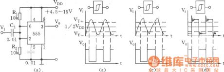
Schmitt trigger which is used in waveform transformation has extensive uses. Figure (a) shows the basic trigger circuit composed of 555. Figure (b),(c),(d) show the converting and transformation of different input signals and waveforms. (View)
View full Circuit Diagram | Comments | Reading(1165)
TTL Interface And Monostable Trigger Circuit
Published:2011/5/9 5:09:00 Author:Sue | Keyword: TTL, Interface, Monostable, Trigger

In a TTL Four-2 input and NOT gate circuit, when there is a positive pulse, after inverse triggering monostable trigger circuit composed of 555 and R1,C1, the output pulse can connect with any TTL circuit or CMOS circuit. (View)
View full Circuit Diagram | Comments | Reading(1405)
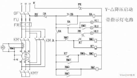
Electric Motor Triangle Voltage Reducing Start Circuit
Published:2011/5/6 11:15:00 Author:Joyce | Keyword: Electric Motor, Triangle, Voltage Reducing, Start
View full Circuit Diagram | Comments | Reading(636)
Arbitrarily Extended Charging Pulse Counter Switch Circuit
Published:2011/5/9 5:10:00 Author:Sue | Keyword: Arbitrarily Extended, Charging, Pulse, Counter, Switch
As seen in the figure, the counter switch circuit consists of a pulse control electronic switch and a time-delay circuit. (View)
View full Circuit Diagram | Comments | Reading(1210)
Touch Controlled Silicon Zero Passed Switch Circuit (2)
Published:2011/5/9 5:13:00 Author:Sue | Keyword: Touch, Controlled, Silicon, Zero Passed, Switch
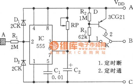
1.Timing disconnection
2.Timing connection (View)
View full Circuit Diagram | Comments | Reading(695)
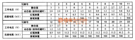
TMP87P538N single-chip microcomputer integrated circuit diagram
Published:2011/5/8 21:42:00 Author:Ecco | Keyword: single-chip , microcomputer, integrated circuit
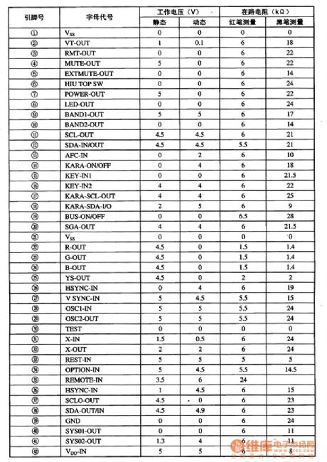
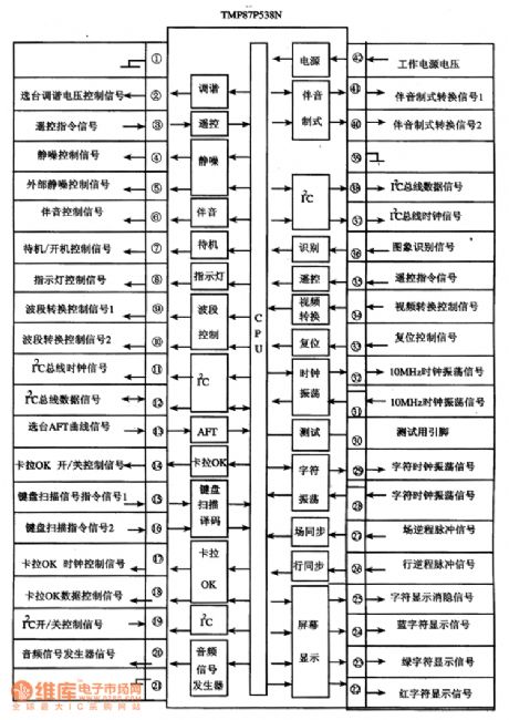
TMP87P538N is the single-chip microcomputer integrated circuit produced by Toshiba, it is widely used in Changhong, Toshiba series of movement and assembly of large-screen color TV. 1. Features of functionsTMP87P538N integrated circuits is mainly composed of the central processing (CPU), clock oscillator circuit, the reset control circuit, I2C bus control circuit, remote control command signals processing circuit, the character generation and processing circuit, the switch control power conversion circuit, keyboard scan decoding circuit, squelch control circuit, audio format conversion circuit, and other control and auxiliary functions circuit, its block diagram is shown in Figure 1.Figure 1 shows the circuit block diagram and pin functions and signal flowing of TMP87P538N integrated.2. Pin functions and data TMP87P538N integrated circuit uses the package with 42 feet in double rows, the pin functions and signal flowing are shown in Figure 1, the pin letter code and data are listed in Table 1. Table 1 shows TMP87P538N pins letter code and data of integrated circuit.
(View)
View full Circuit Diagram | Comments | Reading(826)
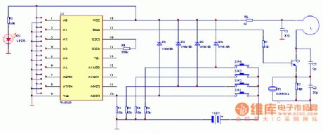
Key Ring Wireless Encoding Remote Controller Circuit (2)
Published:2011/5/9 5:10:00 Author:Sue | Keyword: Key Ring, Wireless, Encoding, Remote Controller
As seen in the figure is the key ring wireless encoding remote controller circuit. (View)
View full Circuit Diagram | Comments | Reading(528)
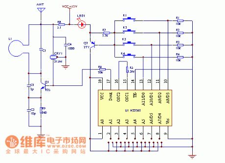
Key Ring Wireless Encoding Remote Controller Circuit (1)
Published:2011/5/9 5:11:00 Author:Sue | Keyword: Key Ring, Wireless, Encoding, Remote Controller
As seen in the figure is the key ring wireless encoding remote controller circuit. (View)
View full Circuit Diagram | Comments | Reading(491)
| Pages:1919/2234 At 2019011902190319041905190619071908190919101911191219131914191519161917191819191920Under 20 |
Circuit Categories
power supply circuit
Amplifier Circuit
Basic Circuit
LED and Light Circuit
Sensor Circuit
Signal Processing
Electrical Equipment Circuit
Control Circuit
Remote Control Circuit
A/D-D/A Converter Circuit
Audio Circuit
Measuring and Test Circuit
Communication Circuit
Computer-Related Circuit
555 Circuit
Automotive Circuit
Repairing Circuit