
Circuit Diagram
Index 1904
Universal Dual Power Dual op-amp circuit
Published:2011/5/10 23:07:00 Author:John | Keyword: Dual Power, Dual op amp
Operational amplifiers CF1458 series are amplifiers with high performance dual op amp, whose electrical performance is the same with that of the amplifier /-A747. But the arrangement of pin for these series is different from each other.The features of these series are listed in the following. No external frequency compensation components are needed. And the amplifiers are provided with short circuit protection and the ability to offset voltage to zero. Besides, there is a wide input voltage range for differential mode and common mode. It has low power consumption and no obstruction. Substitutions or direct models can be amplifiers CF1558MT, CF1458CT, CF1558NMT, CF1458NCT, CF1558SMT, CF1458SCT, CF1558MD, CFl458CD, CFl558MJ, CFl458cJ, CFl458CP, CFl558NMD, Fl458NCD, CFl558SMJ, CFl458SCJ, CFl458SCP, CFl558SMD and so on. Amplifiers CFl458N and CFl558N are able to work with low noise. And amplifiersCFl458S and CFl558S can work with high conversion rate. (View)
View full Circuit Diagram | Comments | Reading(927)
High Performance Power Amplifier Circuit
Published:2011/5/9 2:03:00 Author:chopper | Keyword: High Performance, Power Amplifier
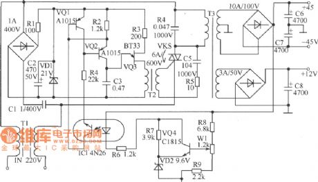
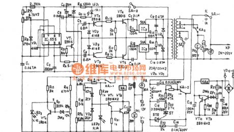
As shown in figure is a high performance power amplifier circuit.It has a feature of small volume,high-power and high-efficiency.Principle of work:AC power is divided into two parts through filtering by T1.One of them is used to reduce voltage of transformer T3.In Primary windings of T3 there is a bidirectional thyristor KS,which is used to change primary AC power of transformer T3.The other one is rectified after voltage reduction by capacitor C1 and provides trigger control circuit with DC working voltage after voltage regulation by VD1.R3、C3、VQ3 and transformer T2 form a oscillating relaxation circuit.R2、R4 and VQ1、VQ2 constitute current supply and offer constant-current charge to capacitor C3.When voltage of C3 reaches the puncture voltage of VQ3,C3 will discharge through the emitter、base of VQ3 and primary coil of transformer T2.And,C3 will get triggering pulse of thyristor KS at the secondary end of transformer T2 and make thyristor conductive, make transformer T3 running.At the secondary end of transformer T3,C3 gains the required positive and negative symmetrical DC voltage of a power amplifier by rectifying and filtering. (View)
View full Circuit Diagram | Comments | Reading(1414)
Light-operated Starter Circuit
Published:2011/5/9 0:37:00 Author:chopper | Keyword: Light-operated, Starter
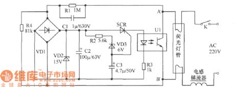
The traditional starter of fluorescent lamp is neon-tube.The start time of neon starter is greatly affected by ambient temperature and voltage,so that its utility is not ideal.As shown in figure is a light-operated starter circuit,it can solve the problems that fluorescent lamps start slowly or cannot start because of temperature reduction and voltage changes.The main component of circuit are thyristor and photo-coupler.When switch K is on,220V commercial power is reduced by fluorescent filament and R1,RC C1 and divided by R4,then,commutated by bridge rectifier VD1,filtered by C2,and through 15V voltage-regulator diode VD2,and,finally,the commercial power offers electricity to unidirectional thyristor and photo-coupler.The control voltage of unidirectional thyristor is offered by voltage-regulator diode VD3 as well as C3 and the thyristor SCR can be connected within 1s.Then,LED of photo-coupler U1 is on power and photistor is connected by light,bringing lots of electric current to fluorescent filament to preheat. Moreover,the conductive photistor makes the control end of electronic starter short and the starter shuts down.Thus,photistor of photo-coupler stops working,which is equal to a filament circuit cut. (View)
View full Circuit Diagram | Comments | Reading(3432)
Phone With Musical Songs(II)Circuit
Published:2011/5/9 0:36:00 Author:chopper | Keyword: Phone, Musical Songs
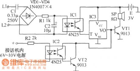
The ring call may make peoplenot able todistinguish which phoneis ringing when one office has many phones.There is a solution that changing the neighboring phone's ringing to different musical sounds.As shown in following figure is a circuit that can do so.IC3 of the figure is a music integration circuit.IC1 and IC2 are photocouplers.When the phone is on-hook,IC1 stops and IC3 outputs nothing,loudspeaker SP does not ring.When there is a call,LED of IC1 will be brilliant because of the AC ringing voltage and the photosensitive tube will be conducted to trigger IC3.The output signal is amplified by VT1 to make SP send out a musical sound.After the phone is off-hook, 6V~10V DC voltage generating within the phone makes IC2 runs, the multiple-unit tube of photosensitive tube and V12 is saturated.Then,output signal of IC3 is short,and SP stops ringing.At this time,the communication is available.The circuit will return to the original state. (View)
View full Circuit Diagram | Comments | Reading(730)
Burglar Alarm Circuit
Published:2011/5/10 0:43:00 Author:chopper | Keyword: Burglar Alarm
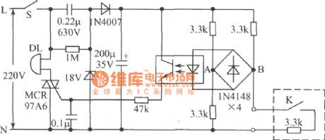
As is shown in figure is a burglar alarm circuit. Detection circuit in the figure adopts resistance bridge and the switch of door adopts magnetic operation switch.The switch will be conducted when door closes while it will be stoped when door opens.The switch and a resistor of electrical bridge form a arm of the electrical bridge,which is set up in the hovel.Thus, if the door is unclenched,the magnetic operation switch will stop;And if exterior line is short or disconnective,in both cases,the bridge circuit will lose balance.The voltage of A、B through rectifier bridge 1N4148 makes optical-coupler run,therefor makes bidirectional thyristor connected and then the bell sends out a alarm.We get supply voltage through the process of voltage reduction by capacitor, half-wave rectification and voltage stabilization by 18V stabilivolt.The switch of door can adopt a magnetic operation switch which is always on as well as microswitch or micro-button.One resistor of the bridge-arms must be set up with the switch.Cut off the power when it needs not to give an alarm,or it will ring even if you yourself opens the door. (View)
View full Circuit Diagram | Comments | Reading(2037)
Integrated inside circuit box circuit
Published:2011/5/9 5:06:00 Author:John | Keyword: Integrated circuit, inside circuit box

(View)
View full Circuit Diagram | Comments | Reading(592)
SN75480 High Voltage Seven Segments Decoder/Cathode Drive Circuit
Published:2011/5/11 0:01:00 Author:chopper | Keyword: High Voltage Seven Segments Decoder, Cathode drive
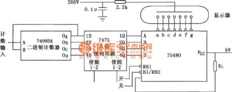
As shown in figure is ahexadecimal SN75480 drive gas discharge display circuit.
(View)
View full Circuit Diagram | Comments | Reading(1130)
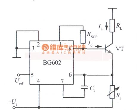
Adjustable constant current source circuit diagram composed of BG602
Published:2011/5/11 1:32:00 Author:Ecco | Keyword: Adjustable , constant current source
View full Circuit Diagram | Comments | Reading(1050)
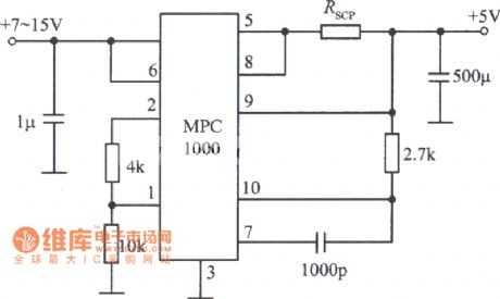
5V, 3A regulated power supply circuit diagram composed of MPC1000 integrated regulator
Published:2011/5/11 1:39:00 Author:Ecco | Keyword: 5V, 3A , regulated power supply , integrated regulator
View full Circuit Diagram | Comments | Reading(1065)
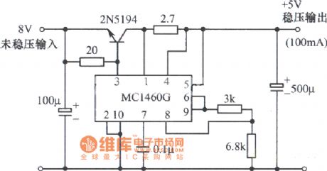
5V regulated power supply circuit diagram composed of MC1460G integrated regulator
Published:2011/5/11 1:40:00 Author:Ecco | Keyword: 5V , regulated power supply, integrated regulator
View full Circuit Diagram | Comments | Reading(621)
JZ Series-II of 150W multi-function emergency power supply circuit diagram
Published:2011/5/11 1:46:00 Author:Ecco | Keyword: JZ Series-II , 150W , multi-function , emergency power supply
JZ Series-II of 150W multi-function emergency power supply circuit diagram is shown as the chart.
(View)
View full Circuit Diagram | Comments | Reading(852)
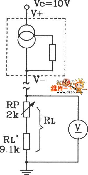
Availability of positive and negative output ideal diode circuit
Published:2011/5/10 1:11:00 Author: | Keyword: Availability of positive and negative output


Circuit function
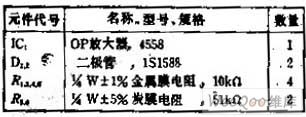
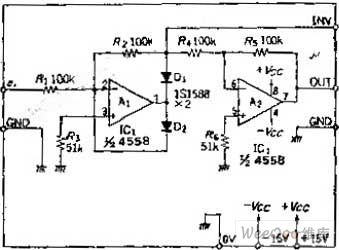
The common diode has forward voltage drop and can not do tiny signal rectifier, and when the signal amplitude is large, if the ambient temperature increases, the rectifier voltage will change with it,it is difficult to form high-precision circuit. Ideal diode circuit can get zero diode characteristic.This circuit can be realized by the feedback circuit of OP amplifier.
Circuit work
OP amplifier A1 is the negative output's ideal diode circuit, cascades diode D1 with the output and starts to feedback from the positive of D1.In terms of the positive input signal , A1 only plays the role of a simple inverting amplifier.
When negatively inputs, OP amplifys the output of A1 to be positive, D1 is disconnected.In order to ensure the circuit works in the open-loop state and to prevent saturation, it also cascades diode D2 with the output. The positive output of A1 is clamped by diode forward voltage drop. OP Amplifier A2 is a inverting amplifier that the magnification is 1,whose function is to reverse the output of A1. If using a unipolar output, the A2 removes. Circuit R3, R6 's function is using the bias current IE of the OP amplifier's inputto eliminate offset voltage, if choosing the FET input OP amplifier ,it can be removes R3, R6.
(View)
View full Circuit Diagram | Comments | Reading(834)
JDE-200 multi-function emergency power supply circuit diagram
Published:2011/5/11 1:47:00 Author:Ecco | Keyword: multi-function, emergency power supply
JDE-200 multi-function emergency power supply circuit diagram is shown as the chart.
(View)
View full Circuit Diagram | Comments | Reading(1394)
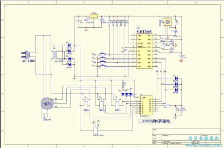
Straw And Feed Muller Control Circuit
Published:2011/5/6 3:07:00 Author:Robert | Keyword: Straw, Feed, Muller
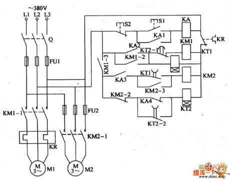
For the straw feed muller used in the countryside to process the corn, straw and grass and other animal feeding stuffs, some people use two electric motor (feeding motor and cropping motor) as the power to complete the crushing job for straw and feed. To avoid the cropping motor's rotor locking, it is required that the cropping motor should run firstly for a period time, and then lets the feeding motor run. The straw feed muller control circuit introduced by this model can control the two motors' woking status automatically.The circuit's working principle is shown below.This straw feed muller control circuit is made up by knife switch Q, fuse FU1, FU2, thermal relay, AC connector KM1, KM2, time relay KT1, KT2, middle relay KA and control button S1, S2 and so on, which is shown in the picture.The cropping motor M1's main circuit is made up by Q, FU1, KM1's normally open main contactor KM1-1, KR thermal elements.The feeding motor M2's main circuit is made up by Q, FU1, FU2 and KM2's normally open main contactor KM2-1.The control circuit is made up by start button S1, stop button S2, KA, KM1, KM2, KT1, KT2 and other control contactors. (View)
View full Circuit Diagram | Comments | Reading(1022)
AC Voltage Regulator One
Published:2011/5/7 5:16:00 Author:Joyce | Keyword: AC Voltage Regulator, One
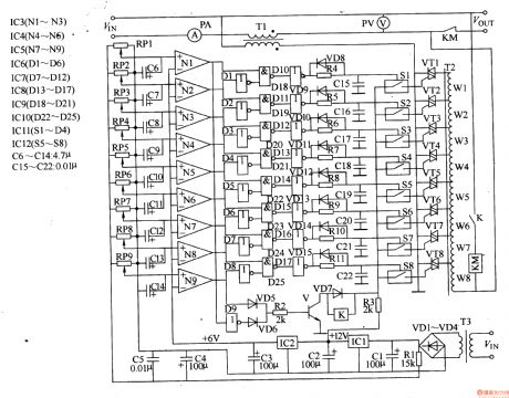
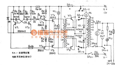
Here is an introduction of an automatic non-contactor compensating AC stabilizer.It changes second offset voltage by controlling primary voltage of the transformer,thus solving the power outages problems in regulating the circuit.The input voltage of AC stabilizer is 167 - 264V,and output voltage is 220 (1土5%) V.Operating principleThe AC stabilizer circuit consists of a power supply voltage-stabilising circuit,an input comparison circuit, a coding control circuit,a compensating output circuit and overvoltage/undervoltage protection circuit , as shown in figure 5-40.
The power supply voltage-stablising circuit consists of power transformer T3, commutation diode VDl- VD4, filter capacitor Cl - C3 and three-terminal integrated regulator IC1,IC2. The Input comparison circuit consists of resistors Rl,potentiometerRPl - RP9, capacitorsC6 - Cl4 and N1- Ng within integrated circuit lC3-1C5 of operational amplifiers .The Coding control circuit consists of NOT gate integrated circuitIC6 -1C8 , NAND gate integrated circuit IC9, IC10,glaze diode VD8 - VDl5, resistorsR4 - Rll and capacitors C15 -C22 .The compensating output circuit consists of integrated circuit ICl (Sl - S4), ( IC17S5 - S8) of electronic switch ,thyristor VTl-VT8, main compensating transformer Tl, assistant compensating transformer T2, AC contactors KM and voltmeter PV, ammeter PA .The over-voltage/under-voltage protection circuit consists ofNOT gate D9 witin IC7 , diodes VD5 - VD7, resistors R2, R3, transistor V and relay K.The assistant compensating transformer is a bodying transformer, which would provide different primary voltages to fulfill different second compensating voltages of T1 . (View)
View full Circuit Diagram | Comments | Reading(4982)
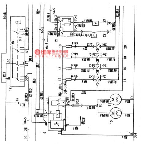
Shanghai GM Chevrolet Sail Car External Lighting System Circuit (3)
Published:2011/5/10 21:54:00 Author:Robert | Keyword: Shanghai GM, Chevrolet, Sail, External Lighting System
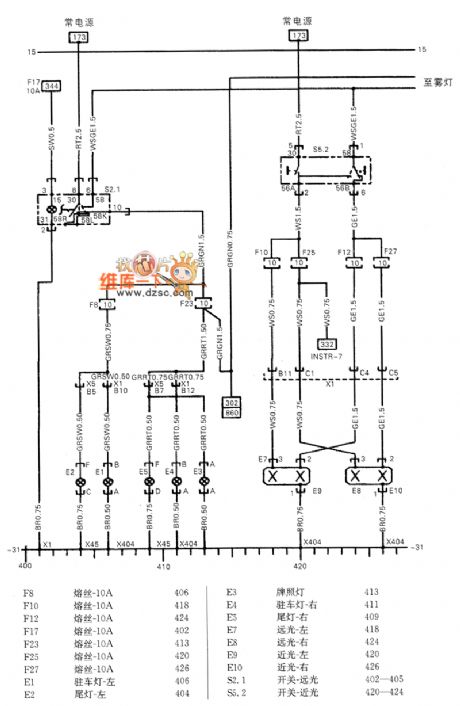
The Shanghai GM Chevrolet Sail CarExternal Lighting System Circuit (3)--parking light, tail light and front headlight short-distance beam/ far beam is shown below.
(View)
View full Circuit Diagram | Comments | Reading(856)
Crops Automatical Frost Protection Control Circuit
Published:2011/5/11 1:24:00 Author:Robert | Keyword: Crops, Frost Protection, Control
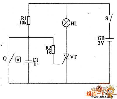
The circuit's working principle is shown below.This crops automatical frost protection control circuit is made up by electrical-contact mercury thermometers Q, control circuit and ignition component and other components which is shown in the picture below.The difference between the electrical-contact mercury thermometers and general mercury thermometers is that this kind thermometers's mercury cavity has been inserted two platinum button electrodes. One is inserted in the upside of the thermometers mercury cavity as a contactor electrode, and the other is inserted in the temperature scale line which need to be controlled as a control electrode. When using this device it should adjust the monitoring and control temperature (combustion smoke temperature) to be +1℃.The control circuit is made up by thyristor VT, resistance R1, R2 and capacitor C.The ignition component is made up by 2.5V little lamp HL and gunpowder etc. First to extract two lines from the two electrode of the little lamp HL, and also use fine sandpaper or fine grinding wheel to rub a small hole in the top of HL glass ball. Then insert some gunpowder from the small hole into the grass ball. Using a appropriate size plastic membrane to wrap up the small lamp HT, and there are about 20g gunpowder in it as the detonator for smoke material. When using this device, accumulate the smoke material on the detonator, and put some soil on the smake material to prevent the burning of smoke material starter.
(View)
View full Circuit Diagram | Comments | Reading(719)
Environmental Temperature Effects On The Non-Operating Current And Operating Current Circuit
Published:2011/5/11 1:25:00 Author:Robert | Keyword: Environmental Temperature, Non-Operating Current, Operating Current
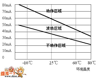
The Environmental Temperature Effects On The Non-Operating Current And Operating Current Circuit is shown below.
1.The maximum working voltage.PTC thermistor is in series in the circuit. When normally working it only has little voltage kept on the PTC thermistor. If the PTC thermistor starts in high impedance status, it would stand nearly the whole power supply voltage. So it should have large enough standing voltage while choosing PTC thermistor, and also should consider the possible wave motion caused by the power supply voltage.2.Non-operating current and operating current.To achieve stable switch functions, the operating current should be at least double of the non-operating current.Because of the environmental temperature's effects on the non-operating current and operating current is so big (see picture 1), the worst case should take into account. For non-operating current, it's best to choose the value at the available maximum environmental temperature. For operating current, it's best to choose the value at the available low environmental temperature.3.Available maximum current at the maximum working voltage.If requiring the PTC thermistor to run the protection function, it needs to check out if the circuit has the conditions of producing larger than the available maximum current, which generally means the possible short circuit situation of the users' application. The specifications document has given the maximum current value, and when using exceeding this value it may cause the PTC thermistor broken or early disabled.
(View)
View full Circuit Diagram | Comments | Reading(600)
SL134 integration temperature sensor forming simple thermometer circuit diagram
Published:2011/5/11 1:46:00 Author: | Keyword: integration temperature sensor, simple thermometer
View full Circuit Diagram | Comments | Reading(847)
The Petrol Jet System Circuit Controlled by Electronics of Santana(32MP003182)
Published:2011/5/11 1:49:00 Author:Borg | Keyword: Petrol Jet System, Santana
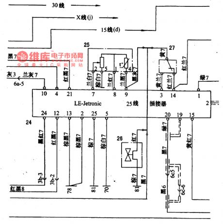
The coil and circuit of thepetrol supply relay 9(as shown in Figure 1 and 2) is under the control of the points ( 15 and 50) of the igniting switch (12) and the steering signals(the intersection of igniting coil 28 and igniting module 31).
When the igniting switch is at the first gear(working normally) and the second(starting), the point of the petrol supply relay is picking up, then the petrol ancillary pump(10) and petrol pump will come into work.
24-petrol jet control unit; 25-air flowmeter and admission temperature sensor; 26-additional air regulator; 27-throttle position sensor; 28-ignition coil; 29-electricity distractor; 30-spark plug; 31-electronic ignition control unit; 32-the signal of the ignition distractor; 32a-explosion sensor; 33-EZK ignition control unit; 34-choke valve/ignition indicator; 35-temperature sensor; 36-choke valve indicating switch (View)
View full Circuit Diagram | Comments | Reading(504)
| Pages:1904/2234 At 2019011902190319041905190619071908190919101911191219131914191519161917191819191920Under 20 |
Circuit Categories
power supply circuit
Amplifier Circuit
Basic Circuit
LED and Light Circuit
Sensor Circuit
Signal Processing
Electrical Equipment Circuit
Control Circuit
Remote Control Circuit
A/D-D/A Converter Circuit
Audio Circuit
Measuring and Test Circuit
Communication Circuit
Computer-Related Circuit
555 Circuit
Automotive Circuit
Repairing Circuit