
Circuit Diagram
Index 1914
Shanghai GM Buick LaCROSSE Car 2.4L Engine Circuit (10)
Published:2011/5/9 5:54:00 Author:Robert | Keyword: Shanghai GM, Buick, LaCROSSE, 2.4L Engine
The Shanghai GM Buick LaCROSSE Car 2.4L Engine Circuit (10) is shown below.
(View)
View full Circuit Diagram | Comments | Reading(521)
Shanghai GM Buick LaCROSSE Car 2.4L Engine Circuit (35)
Published:2011/5/9 5:54:00 Author:Robert | Keyword: Shanghai GM, Buick, LaCROSSE, 2.4L Engine

The Shanghai GM Buick LaCROSSE Car 2.4L Engine Circuit (35) is shown below.
(View)
View full Circuit Diagram | Comments | Reading(511)
MAX16800 Block Diagram Circuit
Published:2011/5/9 9:01:00 Author:Robert | Keyword: Block Diagram
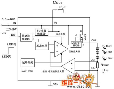
The MAX16800 Block Diagram Circuit is shown below.
(View)
View full Circuit Diagram | Comments | Reading(586)
ABS Square Wave Circuit
Published:2011/5/9 9:04:00 Author:Robert | Keyword: Square Wave
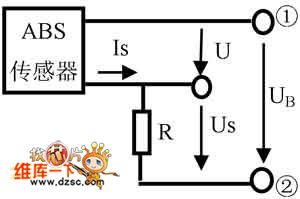
The ABS square wave circuit is shown below.
(View)
View full Circuit Diagram | Comments | Reading(545)
74 series digital circuit 74LS538 3-8 line demultiplexe(three states)
Published:2011/5/9 22:32:00 Author:Nicole | Keyword: 74 series, demultiplexe
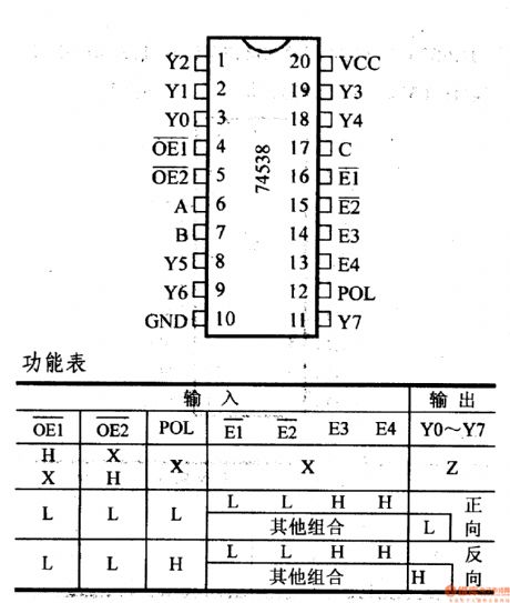
74LS538, 74F538, 3-8 line demultiplexe(three states)
It can switch the positive output or negative output; it has three states output.
(View)
View full Circuit Diagram | Comments | Reading(1062)
Laptop battery charger circuit composed of BQ24700
Published:2011/5/9 22:37:00 Author:Nicole | Keyword: laptop, battery, charger
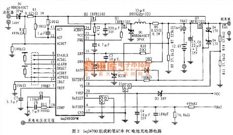
View full Circuit Diagram | Comments | Reading(6885)
Mitsubishi Pajero (PAJERO) brand light off-road vehicle radio and clock principle circuit diagram
Published:2011/5/8 11:31:00 Author:Rebekka | Keyword: Mitsubishi Pajero , light off-road vehicle
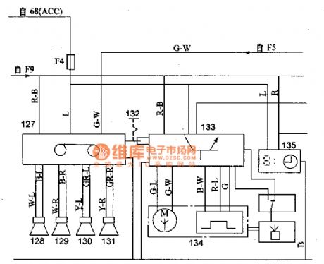
Mitsubishi Pajero (PAJERO) brand light off-road vehicle radio and clock principle circuit diagram.
68 fire switch; 127 radio; 128,129 front left and right speakers; 130,131 rear left and right speakers; 132 automatic antenna switch; 133 automatic antenna controller; 134 automatic antenna motor; 135 Clock (View)
View full Circuit Diagram | Comments | Reading(1298)
Mitsubishi Pajero (PAJERO) brand light off-road vehicle general instrument and the ignition lock illumination timing principle diagram
Published:2011/5/8 12:11:00 Author:Rebekka | Keyword: Mitsubishi Pajero (PAJERO) , light off-road vehicle

Mitsubishi Pajero (PAJERO) brand light off-road vehicle general instrument and the ignition lock illumination timing principle diagram.
136 magnetic sensor; 137 generic instrument; 138 thermal sensor inside the air; 139 car air thermal sensor; 140 ignition switch lighting timer; 141 switch that lights the fire; 142 front door switche.
(View)
View full Circuit Diagram | Comments | Reading(1039)
Ling Pajie years (PAJERO) light off-road vehicle central control door lock set circuit diagram
Published:2011/5/8 11:37:00 Author:Rebekka | Keyword: Ling Pajie years , light off-road vehicle, central control door lock set

Ling Pajie years (PAJERO) light off-road vehicle central control door lock set circuit diagram.
15 lock controller; 16 passenger-side door lock switch; 17 the driver's side door of motor; 18 passenger-side door lock motor; 19 left rear door lock motor; 20 one right after the door lock motors; 21 after the door of motor; 22 auxiliary socket relay; 23 auxiliary socket; 127 Shoufang Ji (View)
View full Circuit Diagram | Comments | Reading(950)
Ericsson telephone battery charger circuit
Published:2011/5/9 22:39:00 Author:Nicole | Keyword: Ericsson, telephone, battery, charger
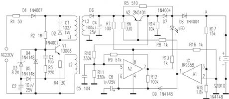
View full Circuit Diagram | Comments | Reading(904)
Telephone charger power supply transformation circuit
Published:2011/5/9 22:25:00 Author:Nicole | Keyword: telephone, charger, power supply
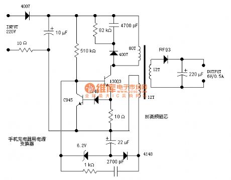
View full Circuit Diagram | Comments | Reading(879)
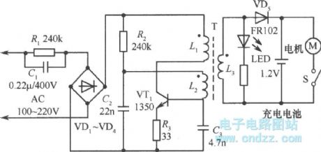
Charger circuit diagram used in beard clipper
Published:2011/5/9 22:22:00 Author:Nicole | Keyword: charger, beard clipper
View full Circuit Diagram | Comments | Reading(1553)
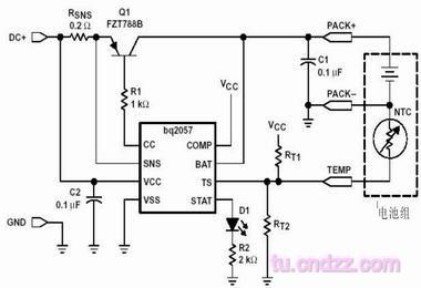
Advanced lithium battery linear charge management IC BQ2057 charge circuit
Published:2011/5/9 22:45:00 Author:Nicole | Keyword: lithium battery, linear charge, management IC
View full Circuit Diagram | Comments | Reading(900)
Intelligent temperature controller MAX6641 circuit diagram
Published:2011/5/10 1:33:00 Author:Nicole | Keyword: temperature controller

As shown in the figure, it uses PWMOUT terminal to drive N channel MOSFET, then to control the fan speed. remote PN junction temperature sensor can be replaced by the emitter junction of microprocessor (μP) internal temperature measurement triode. It also can adopt discrete component triode such as CMPT3906、T3906、KST3906-TF、SMBT3906 and other models. On the conditions of the highest prospective temperature and 10μA current, it requires the forward voltage drop of triode emitter junction should be higher than 0.25V ; on the conditions of the lowest prospective temperature and 100μA current, it should be lower than 0.95V. It should not use high power triode.
(View)
View full Circuit Diagram | Comments | Reading(645)
Constant temperature controller circuit diagram composed of intelligent temperature sensor LM75
Published:2011/5/9 22:55:00 Author:Nicole | Keyword: Constant temperature controller, intelligent temperature sensor
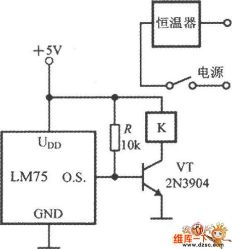
As shown in the figure, it is a simple constant temperature controller circuit which is based on intelligent temperature sensor of IC2 bus interface. LM75 drives relay coil K by 2N3904 transistor, it can control the thermostat power supply's on/off by the high and low of the measured environmental temperature, then it can achieve constant temperature control.
(View)
View full Circuit Diagram | Comments | Reading(1577)
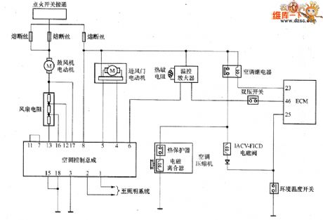
Zhengzhou NISSAN PALDIN car air conditioning system circuit diagram
Published:2011/5/9 21:47:00 Author:Nicole | Keyword: Zhengzhou NISSAN, PALDIN, car, air conditioning system
View full Circuit Diagram | Comments | Reading(687)
TMP87CS38N-1E45A single-chip micro-computer integrated circuit diagram
Published:2011/5/6 3:16:00 Author:Ecco | Keyword: single-chip , micro-computer, integrated circuit
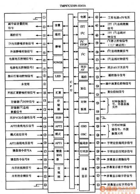

TMP87CS38N-1E45A is a single-chip microcomputer integrated circuit produced by Toshiba, it is widely used in the Konka, Changhong, and other series of large-screen color TV. TMP87CS38N-1E45A uses the package with 42 feet in dual rows, the pin letters code and data are listed in Table 1, the internal block circuit diagram and pin functions and signal flowing are shown in Figure 1. Table 1 shows the pin letters code and data of TMP87CS38N-1E45A integrated circuit.Figure 1 shows the block diagram and in functions and signal flowing of TMP87CS38N IC.
(View)
View full Circuit Diagram | Comments | Reading(1268)
The Wiring Circuit(b) of Volga 3102
Published:2011/5/10 0:30:00 Author:Borg | Keyword: Wiring Circuit, Volga
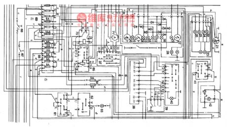
As shown in figure 8 is the wiring circuit(b) of Volga 3102
21-clock; 22-rear window heating indicator; 30-speed-mileage light; 24- high beam indicator; 25-steering lamp; 26-fog lamp; 27- water thermometer; 28-instrument lamp; 29-engine temperature lamp; 30-hand brake indicator; 31-stand-by indicator; 32-brake failure indicator; 33-low oli pressure indicator; 34-oil pressure gauge; 35-oil lack indicator; 36-petrol gauge; 37-ignition switch; 38-flasher; 39-steering and headlight switch; 40-danger alarm switch; 41- heating switches of rear window;42-the cigar-lighter
60-fog lamp relay; 61-fog lamp switch;62-rear fog lamp; 63-rear fog indicator;64-fuse; 65-light lamp; 66-right fuse box; 67-parking lamp switch;68- back-up lamp switch;69-left fuse box; 70-headlight relay;71- current indicator (View)
View full Circuit Diagram | Comments | Reading(1095)
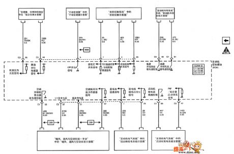
The Ignition Circuit of Santana(32MP003182 chassis)
Published:2011/5/10 2:50:00 Author:Borg | Keyword: Ignition CircuitS, antana
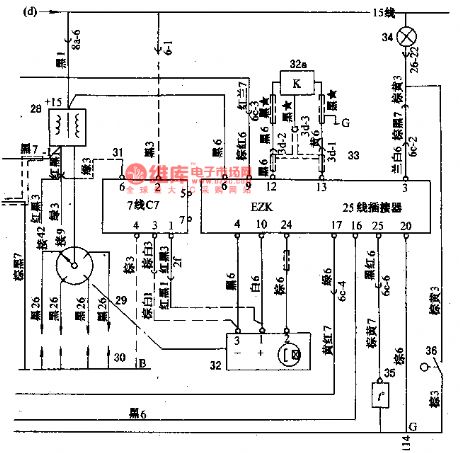
As shown in Figure 1 is that the signal voltage produced by the Hall signal generator (32) of the ignition system is sending to the igniting control unit(EZK) (33), the unit will deliver igniting signals in time according to this signal and signals of explosion sensor 32a, engine coolant temperature signals of thermometer(35) and by computing, this signal is delivered from the points (16 and 17) of EZK to points(15 and 20) of LE-Jetronic, by which the breaking time and the dwell angle controling the elementary circuit is under control, then the sub-coils generate high voltage which is delivered to each cylinder piston(30) by electricity distractors(29).
In the figure, there is also a ignition control module (31) which is connected with the Hall signal generator and igniting coils by a dotted line, this is a stand-by project. If there weren’t the petrol jet control unit(24) and igniting control unit(33), the ignition circuit would be like Santana LX, GX,etc. (View)
View full Circuit Diagram | Comments | Reading(651)
Lamp broken wire detection circuit diagram
Published:2011/5/9 21:06:00 Author:Nicole | Keyword: lamp, broken wire, detection
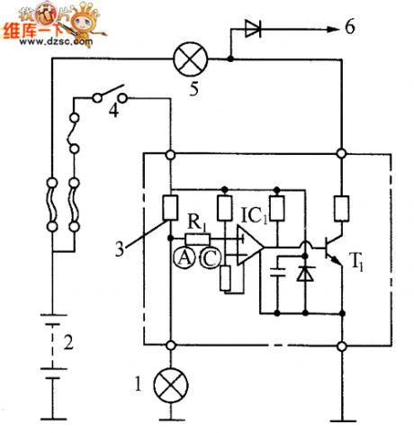
The lamp broken wire detection circuit is shown in the figure. The circuit internal has comparison amplifier IC1, it is a special integrated circuit for detecting broken wire, C point has reference voltage. In normal condition, current tests resistance R, this current should be larger than reference current, A point voltage is lower than reference voltage, the output of comparison amplifier IC1 is 0, transistor T cuts off, the alarm lamp is off.
When it is failure, the current on resistance R1 reduces, A point level rises and even higher than reference voltage, then the output of comparison amplifier IC1 is 1, the base of transistor T has current, T1 turns on, alarm lamp lights, it shows the circuit is failure.
(View)
View full Circuit Diagram | Comments | Reading(1367)
| Pages:1914/2234 At 2019011902190319041905190619071908190919101911191219131914191519161917191819191920Under 20 |
Circuit Categories
power supply circuit
Amplifier Circuit
Basic Circuit
LED and Light Circuit
Sensor Circuit
Signal Processing
Electrical Equipment Circuit
Control Circuit
Remote Control Circuit
A/D-D/A Converter Circuit
Audio Circuit
Measuring and Test Circuit
Communication Circuit
Computer-Related Circuit
555 Circuit
Automotive Circuit
Repairing Circuit