
Circuit Diagram
Index 859
The infrared temperature control circuit composed of heat releasing electric sensors
Published:2011/7/20 1:18:00 Author:Borg | Keyword: infrared temperature control circuit, heat releasing electric sensors
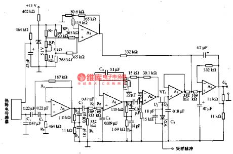
The temperature compensation circuit consists of RT and A1. A6 composes the addition circuit, A6 adds up the outputs of the temperature compensation circuit and the synchronous rectifier circuit, whose output is the corresponding voltage of the object temperature under test. In figure (b) is the amplifier part, detection part, timing part and relay drive part and so on of the circuit. The power supply of the circuit is DC 6-8V, the working current is 70mA, the standby current is 2mA, the maximum range of the sensor is 5m, the time is about 5-22S.
(View)
View full Circuit Diagram | Comments | Reading(2021)
EXPANDED_SCALE_ANALOG_METER
Published:2009/7/9 23:38:00 Author:May
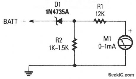
The circuit consists of 0-1 mA meter M1, 6.2-V zener diode D1, and 12-KΩ, 1% resistor R1. R2 is included in the circuit as a load resistor for the zener diode. The value of R2 isn't critical; use a value of 1000 to 1500 Ω. The meter reads from 6 to 18 volts, which is perfect for checking a car's charging system. (View)
View full Circuit Diagram | Comments | Reading(949)
SIMPLE_AUDIO_CLIPPER_LIMITER
Published:2009/7/9 23:37:00 Author:May
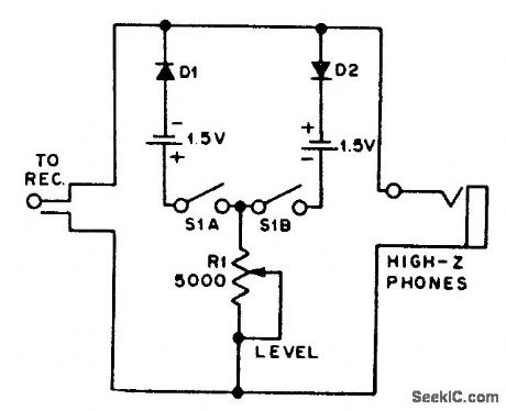
For use with headphones, this circuit sets the audio clipping level via a 5-KΩ pot. This type of noise clipper works best for pulse-type noise of low duty cycle, such as ignition noise. R1 sets the bias on the diodes for the desired limiting level. (View)
View full Circuit Diagram | Comments | Reading(2515)
INFRARED_BURGLAR_ALARM
Published:2009/7/9 23:37:00 Author:May
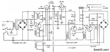
Has electronically modulated infrared light source and synchronous phase sensitive demodulator pick up unit. Pulsed-light technique overcomes adverse effects of continuous or varying ambient light.Alarm goes off if power supply or interconnecting wires are tampered with.Floating 12-v battery takes over load only if power supply fails.C1 tunes T1 to 55-cps oscillator frepuency.-S.Bagno and J.Fasal,Intruder Alarm Uses Phase-Sensitive Detector,Electronics,31:7,p 102-105.
(View)
View full Circuit Diagram | Comments | Reading(1023)
VOLTAGE_SENSING_ALARM
Published:2009/7/9 23:36:00 Author:May
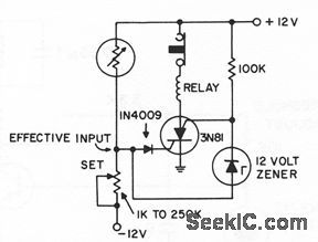
Silicon controlled switch is triggered by input signal more than 1 v above or below ground.- Transistor Manucal, Seventh Edition, General Electric Co., 1964, p 425. (View)
View full Circuit Diagram | Comments | Reading(775)
WAILING_SIREN
Published:2009/7/9 23:35:00 Author:May

C1 is discharged periodically by uit Q1, which resets voltage controlled oscillator to beginning of its frequency sweep. Controlled oscillator also serves as power amplifier, to reduce number of components required. Circuit draws 10 ma front 9.v bottery.-F. J. Harris, Simple Wailing Siren Circuit, EEE, 14:6, p 94. (View)
View full Circuit Diagram | Comments | Reading(2002)
POSITIVE_UMIT_ALARM
Published:2009/7/9 23:34:00 Author:May
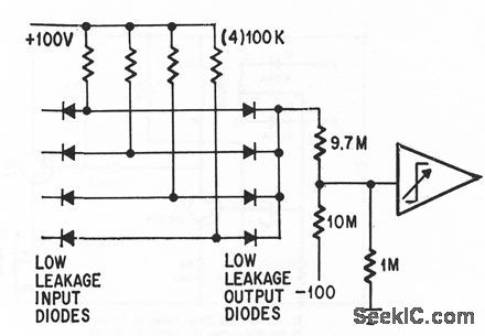
Operafional trigger trips when any output of analog computer goes off scale (above +99 v).-P. Lefferts, Operationctl Trigger For Predse Control, Electronics, 37:28, p 50-55. (View)
View full Circuit Diagram | Comments | Reading(733)
The 3.0L engine CMP sensor, CKP sensor and ICM circuit of Shanghai GM Buick-MPV (GL8)
Published:2011/7/20 2:48:00 Author:Borg | Keyword: CMP sensor, CKP sensor, ICM circuit
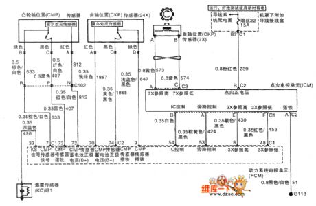
The 3.0L engine CMP sensor, CKP sensor and ICM circuit of Shanghai GM Buick-MPV (GL8)
(View)
View full Circuit Diagram | Comments | Reading(839)
BIPOLAR_REFERENCE_SOURCE
Published:2009/7/9 23:34:00 Author:May
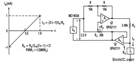
This current source has continuous control of the magnitude and polarity of its amplifier gain and needs only one voltage reference. The circuit includes reference VR, voltage-amplifier circuit A1 with gain-setting resistor RS, and bootstrap-follower amplifier A2. The bootstrapping converts the circuit to a current source and allows the load to be grounded. Any voltage developed across load ZL feeds back to the reference and voltage amplifier, making their functions immune to that voltage. Then the current-source circuitry floats, instead of the load.The voltage reference is connected to both the inverting and noninverting inputs of A1 ; this provides a balanced combination of positive and negative gain. The inverting connection has equal feedback resistors, R, for a gain of -1, and the noninverting connection varies according to the fractional setting, X, of potentiometer RV .X is controls the noninverting gain and adjusting it counters the effect of some of the inverting gain. The value of X is the portion of RV's resistance from the noninverting input of A1 to the temporarily grounded output of A2. Between potentiometer extremes, the current varies with X ± 1 mA. (View)
View full Circuit Diagram | Comments | Reading(991)
The 2.5L(LBB) and 3.0L(LW9) engine circuit of Shanghai GM Buick-Regal (13)
Published:2011/7/20 2:14:00 Author:Borg | Keyword: engine circuit, Buick-Regal
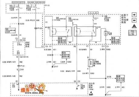
Figure 1. The 2.5L(LBB) and 3.0L(LW9) engine circuit of Shanghai GM Buick-Regal (13) (View)
View full Circuit Diagram | Comments | Reading(506)
Low_noise_equalizing_amplifier_using_an_ECG1019_thin_film_hybrid_module
Published:2009/7/20 2:46:00 Author:Jessie

Low-noise equalizing amplifier using an ECG1019 thin-film hybrid module (courtesy GTE Sylvania Incorporated). (View)
View full Circuit Diagram | Comments | Reading(787)
15_watt_AF_power_amplifier_using_an_ECG1028_module
Published:2009/7/20 2:45:00 Author:Jessie
15-watt AF power amplifier using an ECG1028 module. An ECG1090 module can be substituted for the ECG1028 by omitting the 20K resistor at pin 8 and the 47K resistor between pins 7 and 2 (courtesy GTE Sylvania Incorporated). (View)
View full Circuit Diagram | Comments | Reading(804)
The 2.5L(LBB) and 3.0L(LW9) engine circuit of Shanghai GM Buick-Regal (12)
Published:2011/7/20 2:15:00 Author:Borg | Keyword: engine circuit, Buick-Regal
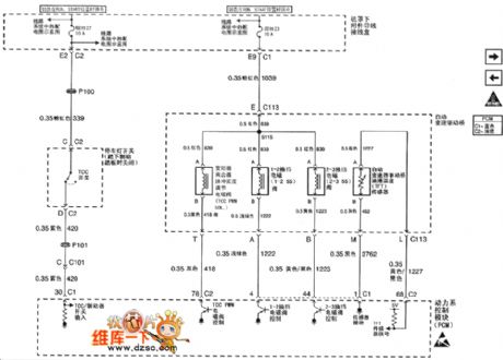
Figure 1. The 2.5L(LBB) and 3.0L(LW9) engine circuit of Shanghai GM Buick-Regal (12) (View)
View full Circuit Diagram | Comments | Reading(441)
LOW_VOLTAGE_ALARM
Published:2009/7/9 23:34:00 Author:May
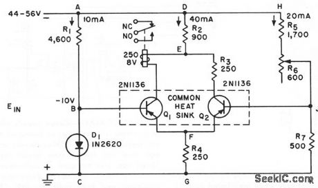
Two-transistor alarm senses 0.2-v drop in telephone system und turns on loctd or remote signalling apparatus.If relay and R3 are interchcnged, circuit will opera as high-voltage alarm,-C.J. Kieffer,Simple Low-Voltage Alarm,Electronics,35:18,p 44-45. (View)
View full Circuit Diagram | Comments | Reading(288)
STEERABLE_ANTENNA_CONTROL
Published:2009/7/20 2:45:00 Author:Jessie
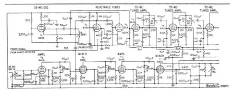
Phase-stabilized 35-Mc uhf amplifier controls directivity of multi-element stationary antenna array. Phase of amplifier output is compared with input reference signal in phase-sensitive detector. System keeps input-output error under 2°.-E. W. Markow, Servo Phase Control Shapes Antenna Pattern, Electronics, 32:1, p 50-52. (View)
View full Circuit Diagram | Comments | Reading(1322)
AUDIO_SHUNT_NOISE_LIMITER
Published:2009/7/9 23:33:00 Author:May
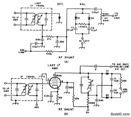
Examples of RF and audio ANL circuits.Positive and negative clipping occurs in both circuits.The circuit at A is self-adjusting.This noise limiter operates at the IF output.It is self-adjusting. Adequate gain is needed at the IF frequency so that several volts p-p of audio is available. (View)
View full Circuit Diagram | Comments | Reading(759)
Low_noise_flat_frequency_response_preamplifier_using_an_ECG1020_thin_film_hybrid_module
Published:2009/7/20 2:44:00 Author:Jessie
Low-noise flat-frequency-response preamplifier using an ECG1020 thin-film hybrid module. At 1 kHz with the switch off typical voltage gain is 66 dB; with the switch on typical voltage gain is 42.5 dB (courtesy GTE Sylvania Incorporated). (View)
View full Circuit Diagram | Comments | Reading(861)
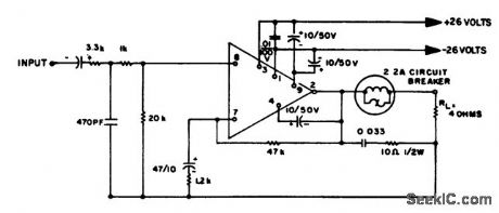
ONE_ZENER_PRECISE_LIMITER
Published:2009/7/9 23:32:00 Author:May
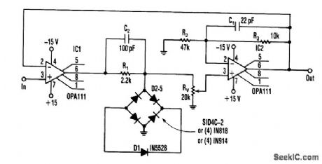
A limiter circuit that requires matched zener diodes can instead use one zener with a full-wave diode bridge. The circuit's two limits are nearly equal when determined by the same zener-only two pairs of forward diodes need to be matched. For best results, an integrated quad of diodes can be used. But, after testing the circuit, four single controlled-drop diodes and four ordinary diodes gave about the same accu-racy (better than 0.5%).
Because the limiting level can be adjusted, zener tolerance can be adjusted out. Gain stability can be optimized by connecting the inverting input to the first op amp to the output of the second to make the circuit inherently unity-gain.
The zener voltage must be increased to 8.2V to compensate for the two diode drops. Placing small capacitors across the resistors in the loop stabilized the circuit adequately and response is orders of magni-tude faster than conventional circuits. Moreover, it's limited primarily by the op amp's slew rate. (View)
View full Circuit Diagram | Comments | Reading(2537)
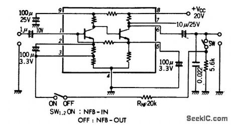
FM_IF_gain_block_with_voltage_regulator
Published:2009/7/20 2:44:00 Author:Jessie
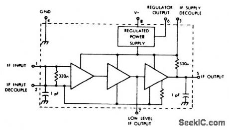
FM IF gain block with voltage regulator. The gain at 10.7 MHz is typically 35 dB.Operating voltage range is 10 to 20 volts. The internal voltage regulator regulates at 7.7 volts and is for external use (courtesy GTE Sylvania Incorporated). (View)
View full Circuit Diagram | Comments | Reading(693)
SHORT_CIRCUIT_ALARM
Published:2009/7/9 23:32:00 Author:May
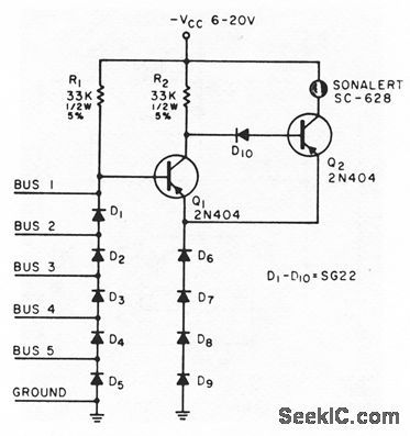
Sounds an alarm if a short occurs between any two of five different voltage buses or between any bus and ground.Used in checking complicted point-to point backplane wiring for computers,to detect wiring errors or solder splashes.-J.J.Russo,Short-Circuit Alarm,EEE,13:6,p 66-68. (View)
View full Circuit Diagram | Comments | Reading(871)
| Pages:859/2234 At 20841842843844845846847848849850851852853854855856857858859860Under 20 |
Circuit Categories
power supply circuit
Amplifier Circuit
Basic Circuit
LED and Light Circuit
Sensor Circuit
Signal Processing
Electrical Equipment Circuit
Control Circuit
Remote Control Circuit
A/D-D/A Converter Circuit
Audio Circuit
Measuring and Test Circuit
Communication Circuit
Computer-Related Circuit
555 Circuit
Automotive Circuit
Repairing Circuit