
Circuit Diagram
Index 852
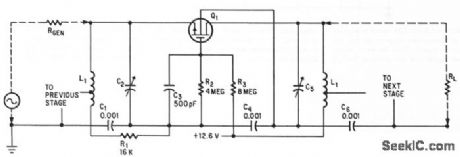
175_MC_R_F_STAGE
Published:2009/7/20 0:23:00 Author:Jessie
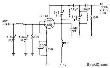
Pi network in grid circuit couples energy from antenna. Double-tuned capacitance-coupled transformer is used in plate circuit.-C. Gonzalez and R. J. Nelson, Design of Mobile Receivers with Low-Plate-Potential Tubes, Electronics, 33:34, p 62-65. (View)
View full Circuit Diagram | Comments | Reading(700)
TWO_TONE_SIREN
Published:2009/7/10 1:39:00 Author:May

This siren provides a constant audio output, but alternates between two separate tones. The LM13080 is set to oscillate at one basic frequency; this frequency is changed by adding a 200-KΩ charging resistor in parallel with the feedback resistor, R2. (View)
View full Circuit Diagram | Comments | Reading(1549)
RESPONSE_BELOW_2_CPS
Published:2009/7/10 1:39:00 Author:May
With input resistance of 1,000 meg,piezoelectric gage amplifier gives gain choices of 1,3,or 10 for loads above 2,500 ohms.Decade input swith can provede choice of shunt capacitances for trimming sensitivety of gages.-Extending Piezoeldtric Gage L-F Response,Electronics,36:4,p 100-103. (View)
View full Circuit Diagram | Comments | Reading(599)
HIGH_FREQUENCY_MOBILE_OSCILLATOR
Published:2009/7/20 0:20:00 Author:Jessie
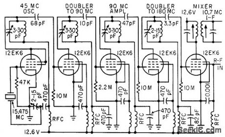
Uses third-overtone crystal oscillator with two doubler stages. To get adequate drive for doubler to 180 Mc, stage of straight-through amplification at 90 Mc is used.-C. Gonzalez and R. J. Nelson, Design of Mobile Receivers with Low-Plate-Potential Tubes, Electronics, 33:34, p 62-65. (View)
View full Circuit Diagram | Comments | Reading(684)
ELECTRONIC_BAGPIPE
Published:2009/7/10 1:38:00 Author:May


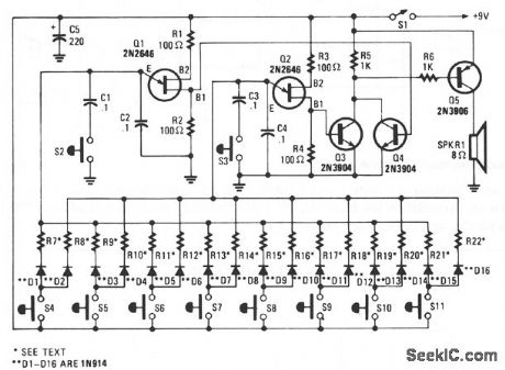
This circuit mimics the dual-tone drone sound that's produced by the unusual wind instrument. Unijunction transistors Q1 and Q2 are connected in similar audio-oscillator circuits. Each of the oscillator frequencies is determined by one of the two resistors selected by one of the pushbutton switches, S4 through S11. The odd-numbered resistors in R7 to R21, determine the frequency for the Q1 oscillator circuit and the even-numbered resistors in R8 through R22, determine the frequency for Q2's circuit.When S4 is pressed, the positive supply is connected to both R7 and R8 through isolation diodes D1 and D2, causing both oscillators to operate. A narrow, fast-rising positive pulse is developed at B1 of both Q1 and Q2 for each cycle of operation. Transistors Q3 and Q4 serve as a simple audio mixer, which is used to combine the pulses from each oscillator. The mixed signal at the collectors of Q3 and Q4 is coupled through R6 to the base of Q5, which amplifies and drives an 8-Ω speaker, SPKR1. Switches, S2 and S3 are used to reduce the oscillator's frequency by about 50% when closed, to produce a new group of tones. (View)
View full Circuit Diagram | Comments | Reading(2321)
COLPITTS_CRYSTAL
Published:2009/7/20 0:18:00 Author:Jessie
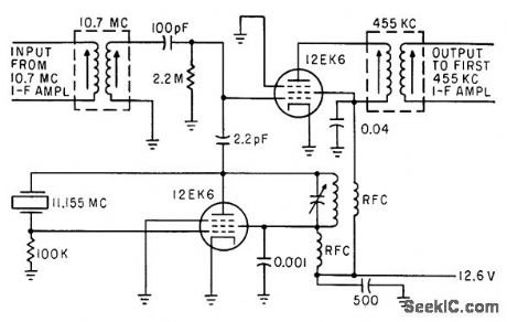
Oscillator uses 11.155-Mc tuned plate circuit for operation at crystal fundamental frequency. Other 12EK6 has no cathode bias and provides conversion gain of 10.-C. Gonzalez and R. J. Nelson, Design of Mobile Receivers with Low-Plate-Potential Tubes, Electronics, 33:34, p 62-65. (View)
View full Circuit Diagram | Comments | Reading(696)
COMPLEMENTARY_IRANSISIOR_AMPLIFIER
Published:2009/7/10 1:38:00 Author:May
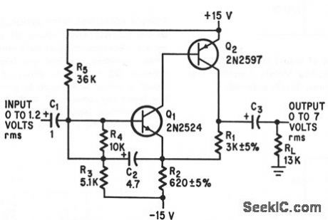
Bootstrapping and negctive loodback Provide 220,000-ohm input impedance and 60,000-ohm ootput impedance with stabilized gain over wide temperaturer range.-L.J.Ernst,Complementary Electronics,37:16,p 92-93. (View)
View full Circuit Diagram | Comments | Reading(702)
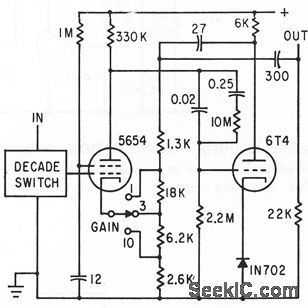
60_DB_GAIN_AT_1_cps_TO_1_MC
Published:2009/7/10 1:37:00 Author:May
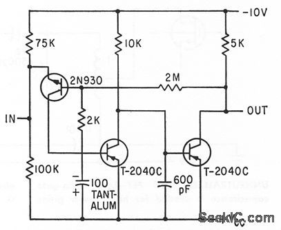
Direct coupled a-c amplifier with feedbock and current defived stabilization uses only two capacitors -P.Lookmann,Direct coupling shrinks Amplifier Size and Cost, Electronics, 36:12, p 66-68. (View)
View full Circuit Diagram | Comments | Reading(630)
Car_turn_signal_reminder
Published:2009/7/20 0:09:00 Author:Jessie
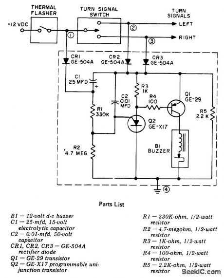
Car turn signal reminder. This circuit is designed for 12-volt negative ground systems only. For cars with a 6-volt negative ground system use a 6-volt buzzer. The circuit cannot readily be adapted for positive ground systems (courtesy General Electric Company). (View)
View full Circuit Diagram | Comments | Reading(1929)
DISCRIMINATOR__AMPLIFIER
Published:2009/7/10 1:36:00 Author:May
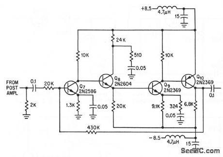
Direct-coupled voltage amplifier of with a-c couplifig at input and output has loop gain of 36 for bond-width of 1 Mc, including low-impedance driver biting Q10.-R. Cuikay and T.Callahan,Or-biting Observatory to Measure Stars'Dim Light,Electronics,37:9,p 28-31. (View)
View full Circuit Diagram | Comments | Reading(701)
Sequential_AC_flasher_using_SCRs_triacs_and_a_UJT
Published:2009/7/20 0:06:00 Author:Jessie
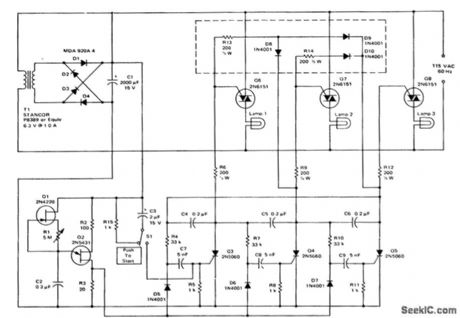
Sequential AC flasher using SCRs, triacs and a UJT. Only three stages are shown but many additional stages can be added. By adding the circuitry inside the dashed lines the circuitry can be modified so that the previous lamps remain on when a new lamp sequences on (courtesy Motorola Semiconductor Products Inc.). (View)
View full Circuit Diagram | Comments | Reading(1072)
AUDIO_GENERATOR
Published:2009/7/10 1:35:00 Author:May
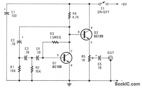
This circuit produces a sinusoidal output of about 8 V pk-pk, which can be varied down to zero, at about 500 Hz. The signal is generated by a phase-shift oscillator. (View)
View full Circuit Diagram | Comments | Reading(1519)
15_volt_fast_blinker_using_an_LM3909
Published:2009/7/20 0:04:00 Author:Jessie
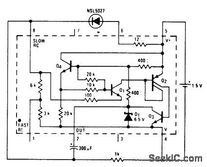
1.5-volt fast blinker using an LM3909. Flashing rate is about 3 hertz. Circuitry inside dashed lines is the LM3909 chip (courtesy National Semiconductor Corporation). (View)
View full Circuit Diagram | Comments | Reading(772)
1_kilowatt_flasher_with_photoelectric_control
Published:2009/7/20 0:03:00 Author:Jessie

1-kilowatt flasher with photoelectric control. This circuit can be used to control warning lights on towers, piers or construction hazards. Remote control can be attained by adding neon lamp N2 and masking PC1 so that it sees only N2 (courtesy General Electric Company). (View)
View full Circuit Diagram | Comments | Reading(739)
AUTOMATIC_VIDEO_GAIN_CONTROL
Published:2009/7/20 0:02:00 Author:Jessie
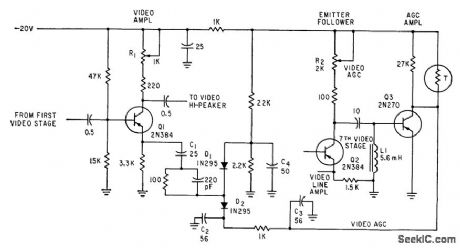
R1 adjusts low-frequency gain of camera video amplifier. Gain control over entire video band is achieved by nonlinear dynamic impedance characteristic of D1 and D2.-D. G. Carreon, Designing Transistorized Television Cameras, Electronics, 33:37, p 72-75. (View)
View full Circuit Diagram | Comments | Reading(885)
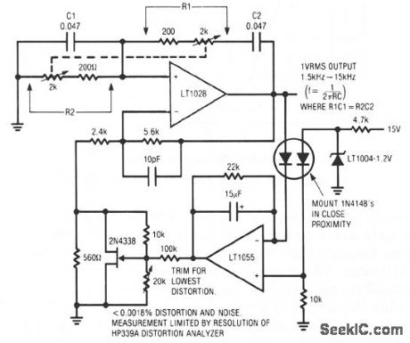
SUPER_LOW_DISTORTION_VARIABLE_SINE_WAVE_OSCILLATOR
Published:2009/7/10 1:35:00 Author:May
View full Circuit Diagram | Comments | Reading(836)
SYNC_SIGNAL_DISTRIBUTOR
Published:2009/7/20 0:01:00 Author:Jessie
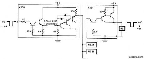
Integrate d circult on two chips distributes synchronizing signal to many television cameras in studio. Delay circuit may be added if needed. Emitter-follower output stage uses Darlington connection for maximum input impedance, while chip for output section (right) uses Darlington to obtain high d-c current gain.-Y. Tarui, Japan Seeks its Own Route lo Improved IC Techniques, Electronics, 38:25, p 90-98. (View)
View full Circuit Diagram | Comments | Reading(992)
OPTICAL_INTERRUPTION_SENSOR
Published:2009/7/10 1:34:00 Author:May
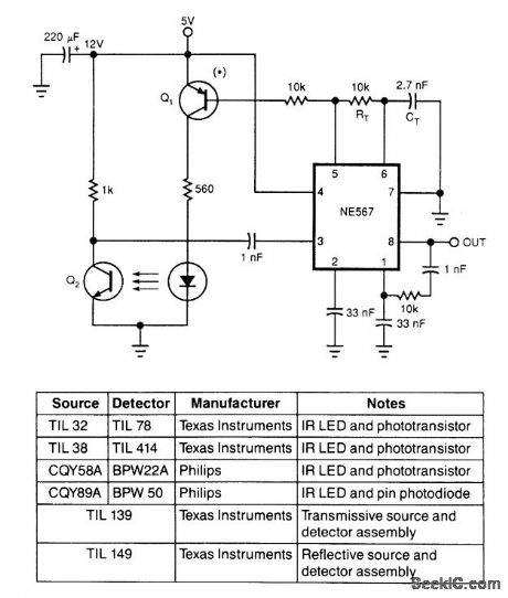
Using only an 8-pin IC and a few discrete components, you can build the infrared optical interrupter. The NE567 tone decoder has all the necessary circuit elements: a local oscillator, a PLL decoder, and a 100-mA output-drive capability. The local oscillator, which is tuned to 40 kHz by RT and CT, drives Q1, a universal low-power silicon pnp transistor (such as a 2N3906, BC559, or ZTX500). Q1 drives the IR-emit-ting diode. The receiving part of the circuit surrounds the IC's internal PLL input at pin 3. When the pho-todetector, Q2, detects the oscillating IR light beam, the 40-kHz signal appears at pin 3 of the IC. Under this condition, the circuit locks and the IC's output is high. When something opaque comes between the LED and Q2, the 40-kHz signal doesn't reach the PLL input, and the IC's output goes low.
The feedback network between pins 1 and 8 prevents the output from chattering. If you connect this circuit to a high-inertia load (such as a mechanical relay), the output doesn't tend to oscillate and you can eliminate these feedback components. The circuit works with virtually any LED-Photodetector pair, but matched pairs allow for longer distances between the emitter and receiver. The table lists some of the best choices. (View)
View full Circuit Diagram | Comments | Reading(3687)
15000_V_FOR_UVICON
Published:2009/7/20 Author:Jessie
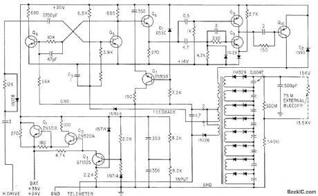
Holds voltage and current output within 1% for 10% in crease or decrease in input. Saturation, related to load current, is sampled at terminals 1 and 2 of output transformer and applied as feedback to control asymmetry of mvbr Q4-Q5, for current control function. Output current is about 15 microamp.-R. N. Riggs, Ultraviolet Space Telescope Will Scan the Stars, Electronics, 35:46, p 37:43.
(View)
View full Circuit Diagram | Comments | Reading(836)
COMMON_GATE_MOS_FET
Published:2009/7/10 1:34:00 Author:May
Power gain of 15 db con be obtained from audio up to 200 Mc.-G. G. luettgenau and S. H. Bctmes, Designing With Low-Noise MOS FETs: A Little Different But No Harder, Eletronics, 37:31, p 53-58.
(View)
View full Circuit Diagram | Comments | Reading(719)
| Pages:852/2234 At 20841842843844845846847848849850851852853854855856857858859860Under 20 |
Circuit Categories
power supply circuit
Amplifier Circuit
Basic Circuit
LED and Light Circuit
Sensor Circuit
Signal Processing
Electrical Equipment Circuit
Control Circuit
Remote Control Circuit
A/D-D/A Converter Circuit
Audio Circuit
Measuring and Test Circuit
Communication Circuit
Computer-Related Circuit
555 Circuit
Automotive Circuit
Repairing Circuit