
Circuit Diagram
Index 842
FM_tuning_indicator_circuit_using_an_ECG1149_14_pin_DIP
Published:2009/7/19 23:05:00 Author:Jessie

FM tuning indicator circuit using an ECG1149 14-pin DIP.Recommended supply voltage is 12 volts.Lamp turn-on voltage at 10.7 MHz is 10 mV(courtesy GTE Sylvania Incorporated). (View)
View full Circuit Diagram | Comments | Reading(1298)
FM_IF_amplifier_for_FM_broadcast_receiver
Published:2009/7/19 23:04:00 Author:Jessie

FM IF amplifier for FM broadcast receiver.Supply voltage can be between 6 and 12 volts,the typical being 7.5 volts,Voltage gainis between 55 and 67 dB,depending on the IF(courtesy GTE Sylvania Incorporated). (View)
View full Circuit Diagram | Comments | Reading(607)
Series_chopper_for_large_input_voltages_using_an_N_channel_JFET
Published:2009/7/19 23:04:00 Author:Jessie
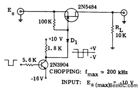
Series chopper for large input voltages using an N-channel JFET (courtesy Motorola Semiconductor Products Inc.). (View)
View full Circuit Diagram | Comments | Reading(644)
THREE_STAGE_VARIABLE_FREQUENCY_CRYSTAL_OSCILLATOR
Published:2009/7/19 23:03:00 Author:Jessie
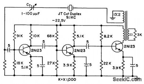
Provides loop transmission of 1, under maximum frequency pulloff of 5 cps from 9.1-kc crystal frequency, and has net phase shift around loop of 360°with crystal in circuit. Third stage provides extra circuit gain needed for larger power output or larger frequency deviations off resonance. Transformer provides phase reversal and reflects desired a-c load, to limit output swing of transistor.-G. A. Gedney and G. M. Davidson, Crystal Oscillator has Variable Frequency, Electronics, 31:7, p 118-119. (View)
View full Circuit Diagram | Comments | Reading(963)
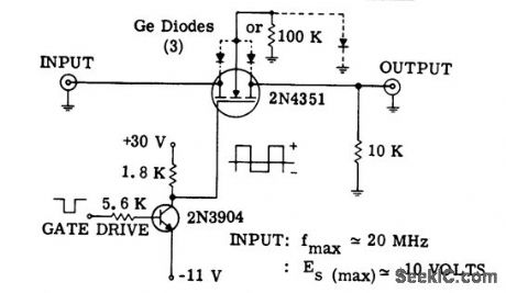
Series_shunt_chopper_for_high_frequency_applications_using_complementary_enhancement_mode_MOSFETs
Published:2009/7/19 23:03:00 Author:Jessie
Series-shunt chopper for high-frequency applications using complementary enhancement mode MOSFETs (courtesy Motorola Semiconductor Products Inc.). (View)
View full Circuit Diagram | Comments | Reading(727)
FM_IF_gain_block_shown_connected_to_typical_FM_receiver_circuitry
Published:2009/7/19 23:02:00 Author:Jessie
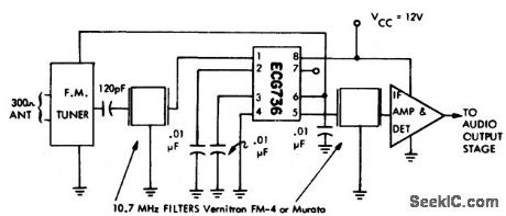
FM IF gain block shown connected to typical FM receiver circuitry. The IF amplifier and detector chip can be an ECG708, for example (courtesy GTE Sylvania Incorporated). (View)
View full Circuit Diagram | Comments | Reading(581)
TONE_OPERATED_CALLING_SYSTEM
Published:2009/7/19 23:02:00 Author:Jessie
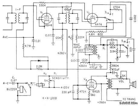
Calling frequency of 2,350 cps is amplified by plate resonant circuit of V2. D1 rectifies this signal and applies positive-going voltage to control grid of last i-f V1,to operate K1 and sound buzzer.-L. Solomon, Citizens Band Equipment Design, Electronics, 33:45, p 70-72. (View)
View full Circuit Diagram | Comments | Reading(621)
MEASURING_OSCILLATOR_STABILITY
Published:2009/7/19 23:02:00 Author:Jessie
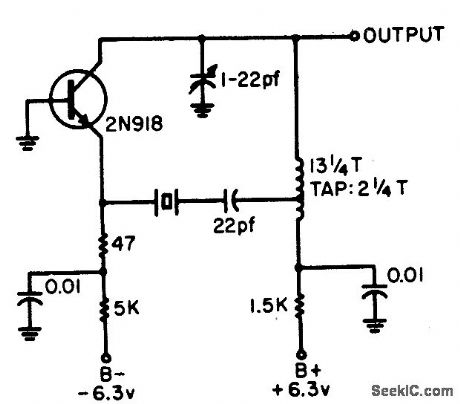
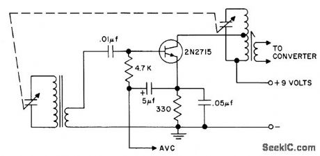
Circuit is used as 90.3125-Mc reference oscillator in system for measuring short-term stability of 45-Mc stalo (stable local oscillator) of airborne radar under high vibration. Tape transformer in collector circuit of transistor controls crystal drive.-J. Coolican, How to Measure STALO Short-Term Stability Under Vibration, EEE, 13:5, p 96-98. (View)
View full Circuit Diagram | Comments | Reading(995)
VOLTAGE_CONTROLLED_23_MC_OSCILLATOR_AND_MODULATOR
Published:2009/7/19 23:01:00 Author:Jessie
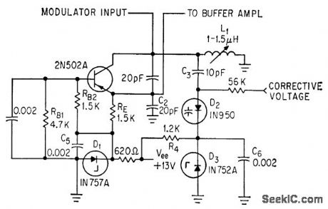
Input signal voltage to transistor changes capacitance of tank circuit, to make oscillator frequency vary with input signal voltage. Variable-capacitance diode requires fewer parts than transistor modulator. Zener diodes provide constant bias for variable-capacitance diode D2.-F. L. Carroll, How to Achieve Stability in Space Telemetry, Electronics, 37:4, p 32-35. (View)
View full Circuit Diagram | Comments | Reading(747)
BOOSTING_INPUT_IMPEDANCE
Published:2009/7/10 2:27:00 Author:May
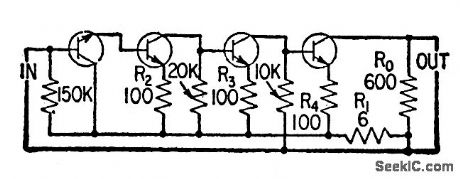
Circuit shows how voltage gain in transistor amplifier can be exchanged for input impedance through use of negative feedback. At same time, voltage gain is made more independent of transistor parameters. -Feedback Increases Input Impedance, Electronics, 32:11, p 150-153. (View)
View full Circuit Diagram | Comments | Reading(748)
FM_stereo_processor_3
Published:2009/7/19 23:01:00 Author:Jessie
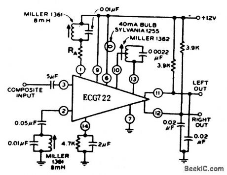
FM stereo processor. The 1 4-pin ECG722 perform the standard stereo functions of 19 kHz amplifier, frequency doubler, stereo indicator lamp driver, and stereo demodulator. Current drain at 12 volts is typically 14 mA (courtesy GTE Sylvania Incorporated). (View)
View full Circuit Diagram | Comments | Reading(622)
BEAT_FREQUENCY_AUDIO_GENERATOR
Published:2009/7/10 2:27:00 Author:May
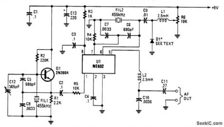
Q1 is a fixed oscillator operating at 455 kHz. U1 is a mixer, with its own internal oscillator running at 455 kHz. FIL1 and FIL2 are Murata CSB455E filters or equivalent. D1 is a vat-actor diode (an IN4002 used as a varactor works well here). R6 controls the bias on D1. When R6 is varied, the oscillator fre-quency varies a few kHz. Audio beat note is taken, through RF filter L2 and C10, from pin 5 of U1.
(View)
View full Circuit Diagram | Comments | Reading(1643)
TUNED_R_F_STAGE
Published:2009/7/19 23:00:00 Author:Jessie
Improves sensitivity, selectivity, and signal-to-noise ratio when used at input of radio receiver.- Transistor Manual, Seventh Edition, General Electric Co., 1964, p 283. (View)
View full Circuit Diagram | Comments | Reading(712)
RACE_CAR_MOTOR_CRASH
Published:2009/7/10 2:27:00 Author:May
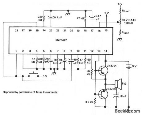
For two simultaneous race-car sounds, the mixer can be multiplexed between the SLF and VCO functions. (View)
View full Circuit Diagram | Comments | Reading(597)
FM_stereo_processor_2
Published:2009/7/19 23:00:00 Author:Jessie
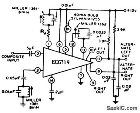
FM stereo processor. The 14-pin DIP performs the standard stereo functions of 19 kHz amplifier, frequency doubler, stereo indicator lamp driver, and stereo demodulator. The l0 also includes two alternate emitter follower outputs (courtesy GTE Sylvania Incorporated). (View)
View full Circuit Diagram | Comments | Reading(614)
100_KHz_CRYSTAL_CALIBRATOR
Published:2009/7/10 2:27:00 Author:May
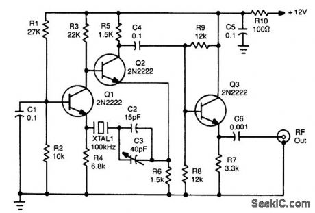
Using a 12-V supply, this crystal calibrator should prove a useful accessory for a SW receiver. Q1 and Q2 form an oscillator and Q3 is a buffer amp. (View)
View full Circuit Diagram | Comments | Reading(2293)
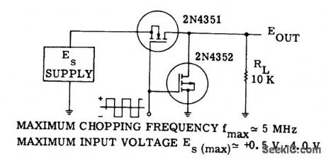
MOSFET_analog_switching_circuit_chopper_for_large_input_voltages
Published:2009/7/19 23:00:00 Author:Jessie
MOSFET analog switching circuit (chopper) for large input voltages (courtesy Motorola Semiconductor Products Inc.). (View)
View full Circuit Diagram | Comments | Reading(606)
TRIODE_CATHODE_FOLLOWER
Published:2009/7/10 2:27:00 Author:May
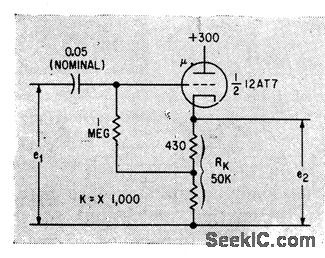
Effective gain stability factor is approximately equal to reciprocal of omplification factor of tube.-G.M. Davidson and R. F. Brady, Unity-Gain AmpliGer Offers High Stability, Electronics, 33:9, p 66-67. (View)
View full Circuit Diagram | Comments | Reading(954)
Alternating_flasher
Published:2009/7/19 23:00:00 Author:Jessie
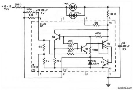
This LM3909 circuit is essentially a relaxation-type oscillator (chapter 5) that flashes two LEDs in sequence. With a 12-V supply, the repetition rate is about 2.5 kHz. Timing and storage capacitor C2 alternately charges through the upper LED and is discharged through the other LED by Q3 within the LM3909. If a red/green flasher is desired, the green LED should have its anode Of plus lead toward pin 5 (like the lower LED). A shorter, but higher, voltage pulse is available in this position. (View)
View full Circuit Diagram | Comments | Reading(0)
FREE_RUNNING_CASCODE_OSCILLATOR
Published:2009/7/19 22:59:00 Author:Jessie
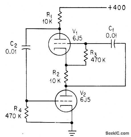
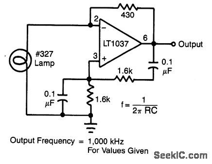
Omission of voltage-divider capacitors from cascode multivibrator gives sine-wave oscillator if loop gain is equal to unity.-C. Sing, Advantages of Free-Running Cascode Multivibrators, Electronics, 37:5, p 28-29. (View)
View full Circuit Diagram | Comments | Reading(739)
| Pages:842/2234 At 20841842843844845846847848849850851852853854855856857858859860Under 20 |
Circuit Categories
power supply circuit
Amplifier Circuit
Basic Circuit
LED and Light Circuit
Sensor Circuit
Signal Processing
Electrical Equipment Circuit
Control Circuit
Remote Control Circuit
A/D-D/A Converter Circuit
Audio Circuit
Measuring and Test Circuit
Communication Circuit
Computer-Related Circuit
555 Circuit
Automotive Circuit
Repairing Circuit