
Circuit Diagram
Index 856
STABLE_40_MC_OSCILLATOR
Published:2009/7/19 23:36:00 Author:Jessie
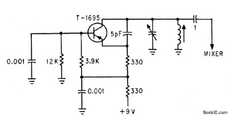
Frequency shifts less than 500 kc when supply voltage is changed from 5 to 12 V.-T. P. Prouty, Using Varactors to Extend Frequency-Control Range, Electronics, 36:45, p 48-49. (View)
View full Circuit Diagram | Comments | Reading(757)
SHORTWAVE_CONVERTER_FOR_AM_CAR_RADIOSS1_
Published:2009/7/10 0:52:00 Author:May
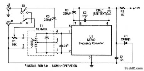
Using a Signetics NE602, this converter tunes the 9.5- to 9.8-MHz range. An AM car radio is used as a tunable IF amplifier. Output is taken from J2, the auto antenna. The crystal (XTAL1) can be a frequency about 1 MHz below the desired tuning range; for 9.5 to 9.8 MHz, an 8.5- to 8.8-MHz crystal should be used. (View)
View full Circuit Diagram | Comments | Reading(2532)
VARICAP_TUNES_TUNNEL_DIODE_OSCILLATOR
Published:2009/7/19 23:35:00 Author:Jessie
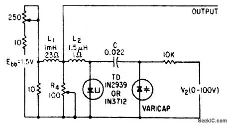
Series oscillator circuit tunes electrically over range of 12 to 22 Mc.-E. Gottlieb and J. Giorgis, Tunnel Diodes-Using Them as Sinusoidal Generators, Electronics, 36:24, p 36-42. (View)
View full Circuit Diagram | Comments | Reading(1909)
BIDIRECTIONAL_COMPOUND_OP_AMP
Published:2009/7/10 0:51:00 Author:May
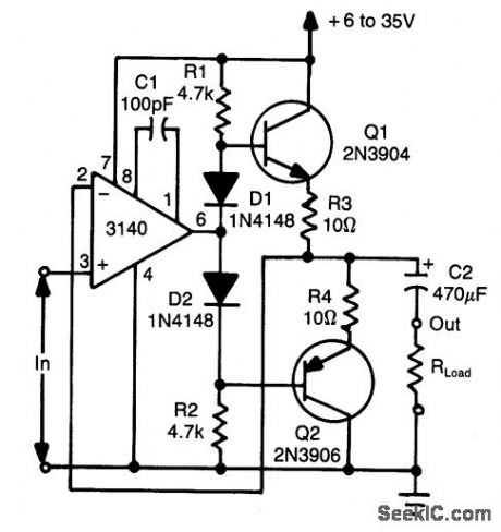
Using two transistors (Q1 and Q2), a bidirec-tional op amp can source or sink up to 50 mA. D1 and D2 provide bias for Q1 to eliminate dead-zone effects. (View)
View full Circuit Diagram | Comments | Reading(683)
AUTOMATIC_LEVEL_CONTROL_FOR_PARAMETRIC_MAPLIFIER
Published:2009/7/19 23:35:00 Author:Jessie
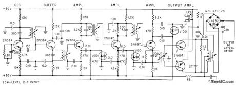
Varactor diode in pump feed line feeds so-called magnifies d-c amplifier that in turn drives ferrite variable attenuator, to hold troposcatter receiver signal level constant over entire klystron mode.-W.L. Smott and H. C. Leahy, Parametric Amplifier Improves Tropo-Scatter System, Electronics, 35:9, p 38-40. (View)
View full Circuit Diagram | Comments | Reading(1332)
10_MHz_WWV_TO_80_METER_SW_CONVERTER
Published:2009/7/10 0:50:00 Author:May
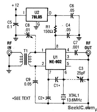
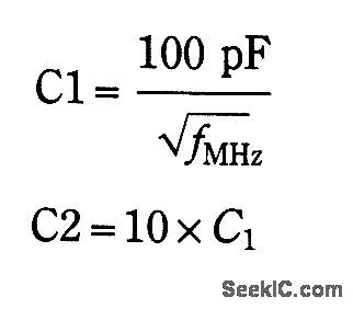

This converter is useful where reception of WWV is desirable and only a ham-band receiver is available. U1 acts as a mixer/oscillator. The values of C1 and C2 are given by: (View)
View full Circuit Diagram | Comments | Reading(687)
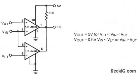
WINDOW_DETECTOR_2
Published:2009/7/10 0:49:00 Author:May
The detector circuit compares the output voltage of two separate voltage dividers with a fixed reference voltage. The resultant absolute error signal is amplified and converted to a logic signal that is TTL compatible. (View)
View full Circuit Diagram | Comments | Reading(685)
DAMPED_40_MC_GENERATOR
Published:2009/7/19 23:34:00 Author:Jessie
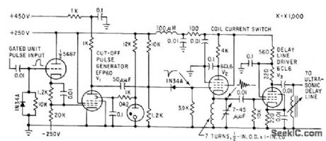
Converts unit pulses, resulting from video screening in nuclear track scanner, to damped 40-Mc oscillations each 0.1 microsec long, which are inserted in quartz ultrasonic delay line that feeds counter.-P. V. C. Hough, J. A Koenig, and W. Williams, Scanner Recognizes Atomic Particle Tracks, Electronics, 32:13, p 58-61. (View)
View full Circuit Diagram | Comments | Reading(804)
High_power_battery_operated_flasher_with_40_watt_output
Published:2009/7/19 23:32:00 Author:Jessie
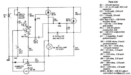
High-power battery-operated flasher with 40-watt output. SCR1 and SCR2 form a basic DC flip-flop (courtesy General Electric Company). (View)
View full Circuit Diagram | Comments | Reading(897)
RECEIVER_FREQUENCY_CONVERTER_STAGE
Published:2009/7/10 0:48:00 Author:May
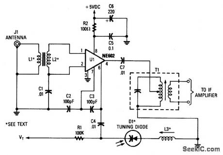
L1, L2 1:12 Tums Ratio Toroid (Broadband).L3 Resonates to L.0. Frequency with D1 capacitance.LO FREQ Desired received frequency ± IF frequency.In this case, the NE602 is used in this superhet front-end configuration. U1 serves as a frequency converter. L1/L2 is a broadband toroidal transformer. A tuned transformer may be used instead. The sup-ply voltage is +5 to +9 Vdc. T1 is tuned to the IF frequency. The typical IF frequency is 455 kHz. This circuit, depending on L1, L2, and L3, should be usable in the frequency range from audio to 30 MHz. The varactor tuning diode can be replaced with an air-variable capacitor, if desired. (View)
View full Circuit Diagram | Comments | Reading(1022)
WINDOW_DETECTOR_1
Published:2009/7/10 0:47:00 Author:May
View full Circuit Diagram | Comments | Reading(0)
PROTECTED_OUTPUT_STAGE
Published:2009/7/19 23:32:00 Author:Jessie
High-voltage passivated mesa transistor in output stage of Japanese home radio is protected by silicon varistor R.-T. Kojima and M. Watanabe, When You're Second, You Try Harder, Electronics, 38:25, p 81-89. (View)
View full Circuit Diagram | Comments | Reading(733)
LIGHT_BEAM_FOR_CONTROL_OF_MOVING_TOY
Published:2009/7/19 23:32:00 Author:Jessie
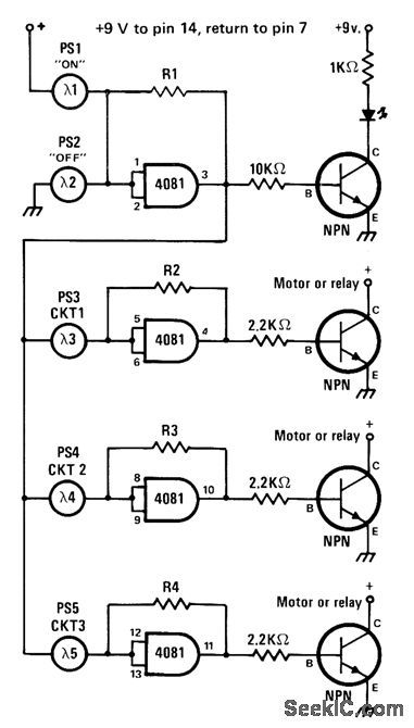
Battery-powered CM0S logic is switched on and off by aiming flashlight beam at photocell, for turning small motors of model train or other powered toy on and off. Transistors can be 2N2222A for most small motors, but larger motors will require power transistors, Use high-intensity flashlight, with shield over lens to restrict beam width, so only one of five photocells is illuminated at a time. LED shows ON/OFF status of circuit. Values of R1-R4 are chosen so each gate flips logic state only when associated photocell is illuminated.-J. Sandler, 9 Projects under $9, Modern Electronics, Sept. 1978, p 35-39. (View)
View full Circuit Diagram | Comments | Reading(873)
2_METER_CONVERTER
Published:2009/7/10 0:47:00 Author:May
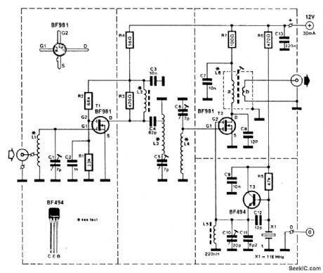
This converter enables a receiver that tunes 28 to 32 MHz to receive the 144- to 148-MHz amateur band. A BF981 dual-gate MOSFET provides RF gain and feeds mixer T2, another BF981. T3 is a 116-MHz crystal oscillator used to provide L.O. injection to T2. Coils are wound on a 6-mm form. L1, L3, and L4 are 8 turns of 1-mm diameter silver-plated copper wire. L2 is 4 turns of 0.2-mm wire through a ferrite lead. L6 has 19 turns on the primary and 3 turns on the secondary. (View)
View full Circuit Diagram | Comments | Reading(6260)
GAIN_CONTROLLED_OP_AMP
Published:2009/7/10 0:46:00 Author:May
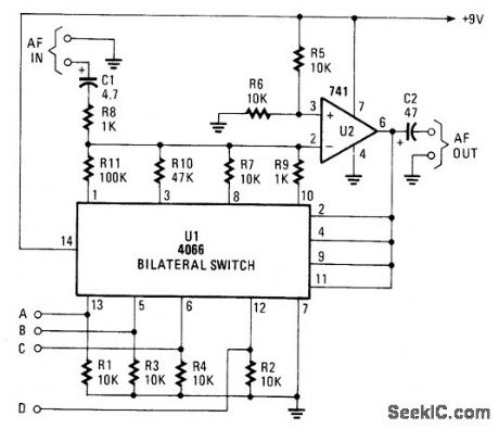
The gain controller uses a 4066 quad bilateral switch to electronically select a feedback resistor for the 741 op amp. One or more switches can be turned on at the same time to produce a stepped, variable-gain range from less than 1 to 100. (View)
View full Circuit Diagram | Comments | Reading(3561)
8_CHOICES_WITH_3_WIRES
Published:2009/7/19 23:30:00 Author:Jessie
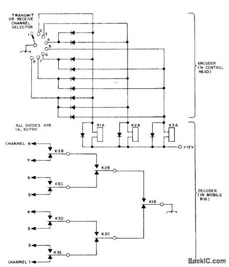
Provides remotely selected choice of eight functions, such as channels in mobile FM station, with only three wires running from control head to controlled equipment that can be in front of car. System involves converting 8-position switch selection in control head to 3-bit binary form for three control wires going to three-relay arrangement for decoding back to 8-position format. Relays are two-pole and four-pole double-throw 12-V units.-G. D. Rose, Independent 8-Channel Frequency Selection with Only Three Wires, QST, Aug. 1974, p 36-40. (View)
View full Circuit Diagram | Comments | Reading(643)
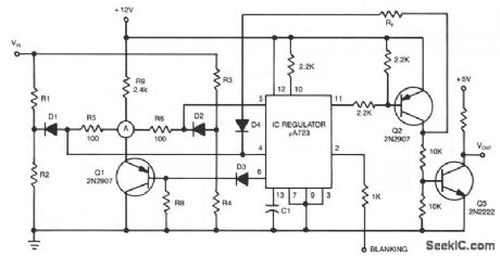
WINDOW_DETECTOR
Published:2009/7/10 0:46:00 Author:May
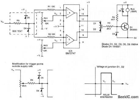
This circuit de-energizes a normally energized relay if the input voltage goes above or below two individually set voltages. The transistor driving the relay is normally turned on by R4, so the relay is normally energized. If the cathode of D1 or D2 is taken negative, Q1 will turn off and the relay will de-energize. The IC is a 72747 dual op amp used without feedback, so the full gain of about 100dB is available. The amplifier output will thus swing from full positive to fullmegative for a few mV change at the input. The relay is therefore only energized if VIN is between VUL and VLL. The two limits can be set anywhere between the supply rails, but obviously VUL must be more positive than VLL. If VIN can go outside the supply rails, D5, D6, and R5 should be added to prevent damage to IC1. If VUL and VLL are required to be outside the supply rails, VIN can be reduced by RV3. The supplies can be any value, providing that the voltage across them is not more than 30 V. (View)
View full Circuit Diagram | Comments | Reading(0)
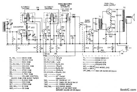
SIX_TRANSISTOR_72_V_1_W_BROADCAST
Published:2009/7/19 23:29:00 Author:Jessie
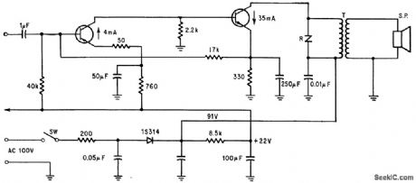
Nominal sensitivity is 150 microvolts per meter. Zero-signal battery drain is 10 ma.- Transistor Manual, Seventh Edition, General Electric Co., 1964, p 293. (View)
View full Circuit Diagram | Comments | Reading(578)
NINE_CHANNEL_DECODER
Published:2009/7/19 23:29:00 Author:Jessie
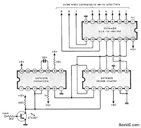
Circuit accepts serial information arriving over data link as series of nine varying-width pulses followed by fixed-width sync pulse, and after detection passes the nine individual commands to their respective servoamplifiers. Use of TTL ICs gives low component count for remote control system. Detection of sync pulse is done by comparing length of inverted input pulses with output of 0.6-ms monostable reference. All command pulses exceed 0.6 ms, so only 0.5-ms sync pulse clears counter to prepare for next channel-1 command pulse. Article gives operating details of system and circuits for coder and servoamplifier.-M.F. Bessant, Multi-Channel Proportional Remote Control, Wireless World, 0ct. 1973, p 479-482. (View)
View full Circuit Diagram | Comments | Reading(1124)
VLF_CONVERTER
Published:2009/7/10 0:45:00 Author:May
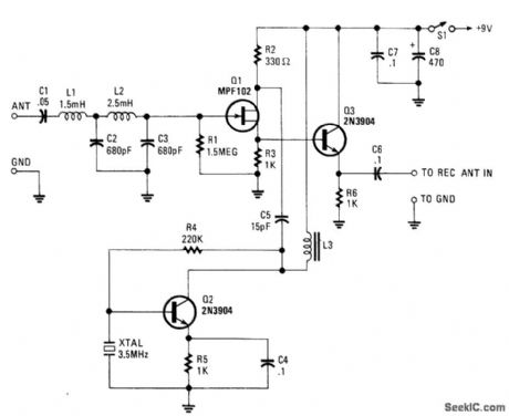
The VLF Converter can be used to pick up signals for the general coverage of shortwave receivers. A number of unusual signals can be heard on frequencies below 15 kHz.This converter wiil convert frequencies from 0 to 250 kHz to 3500 to 3750 kHz so that the LF- and VLF-band segments can be received on an amateur or shortwave receiver that covers 3 500 to 4000 kHz.Signals from a short whip antenna (8 to 10 feet) are coupled through low-pass filter L1/L2/C2/C3 to RF amp Q1. Q3 mixes these signals with a 3.5-MHz signal from Q2 and associated components C4, R5, R4, and 3.5-MHz XTAL. L3 is an RF choke that presents an inductive load to Q3. It should be resonant some-what above 3.5 MHz when placed in the circuit. An adjustable coil of about 30 to 100 μH should be suffi-cient. The converter output is taken from the emitter of Q3 through C6. (View)
View full Circuit Diagram | Comments | Reading(8045)
| Pages:856/2234 At 20841842843844845846847848849850851852853854855856857858859860Under 20 |
Circuit Categories
power supply circuit
Amplifier Circuit
Basic Circuit
LED and Light Circuit
Sensor Circuit
Signal Processing
Electrical Equipment Circuit
Control Circuit
Remote Control Circuit
A/D-D/A Converter Circuit
Audio Circuit
Measuring and Test Circuit
Communication Circuit
Computer-Related Circuit
555 Circuit
Automotive Circuit
Repairing Circuit