
Circuit Diagram
Index 853
SINGLE_SUPPLY_WIEN_BRIDGE_OSCILLATOR
Published:2009/7/10 1:33:00 Author:May
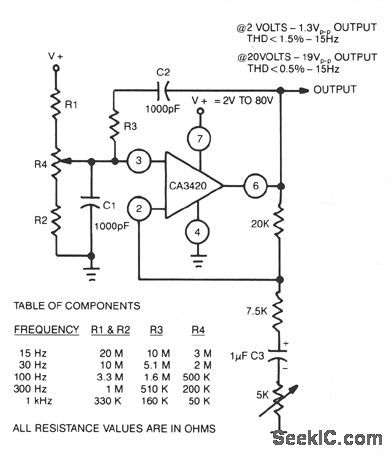
The adjustment of R4 contributes to the comparatively symmetrical output transfer characteristic of the CA3420 BiMOS op amp. To extend the lower operating frequency, remove C3 and use a dual supply. (View)
View full Circuit Diagram | Comments | Reading(1026)
100_MC_FET_AMPLIFIER
Published:2009/7/10 1:33:00 Author:May
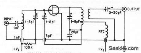
Low-cost insulaled-gate fet circuit can handle signals up to signal volts in uhf range, with inherently low cross.modulation distortion. -Low.Cost Power Booster, Electronics, 37:14, p 29-30. (View)
View full Circuit Diagram | Comments | Reading(721)
50_MC_40_w_POWER_AMPLIFIER
Published:2009/7/10 1:33:00 Author:May
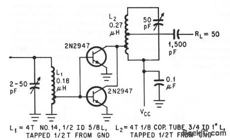
Paralleled silicon transistors operanng as class C are biosed on by incoming r-f signal,hence stop conducting when there is no signal,-R.C.Heihall, Getting Transistors into Single-Side.band Amplifiers, Electonics,37:17,p 72-75. (View)
View full Circuit Diagram | Comments | Reading(766)
R_F_MODULATOR
Published:2009/7/19 23:59:00 Author:Jessie
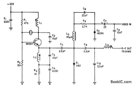
Crystal frequency is half the desired r-f value. L2 and C3 are tuned to second harmonic to give desired r-f channel for tv camera. R-f output is 50 mv into 75-ohm load.-D. G. Carreon, Designing Tran. sistorized Television Cameras, Electronics, 33:37, p 72-75. (View)
View full Circuit Diagram | Comments | Reading(949)
LOW_DISTORTION_THERMALLY_STABILIZED_WIEN_BRIDGE_OSCILLATOR
Published:2009/7/10 1:32:00 Author:May
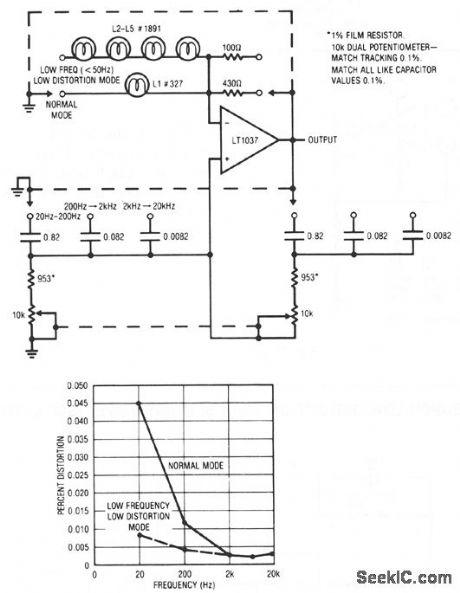
A variable Wien bridge provides frequency tuning from 20 Hz to 20 kHz. Gain control comes from the positive temperature coefficient of the lamp. When power is applied, the lamp is at a low resistance value, the gain is high, and oscillation amplitude builds. The lamp's gain-regulating behavior is flat within 0.25 dB over the 20 Hz-20 kHz range of the circuit. Distortion is below 0.003%. At low frequencies, the thermal time constant of the small normal-mode lamp begins to introduce distortion levels about 0.01%. This is because of hunting when the oscillator's frequency approaches the lamp's thermal time constant. This effect can be eliminated, at the expense of reduced output amplitude and longer amplitude settling time, by switching to the low-frequency, low-distortion mode. The four large lamps give a longer thermal time constant, and distortion is reduced. (View)
View full Circuit Diagram | Comments | Reading(835)
Alternating_flasher_using_an_LM3909_chip
Published:2009/7/19 23:58:00 Author:Jessie
Alternating flasher using an LM3909 chip. Circuitry inside the dashes is the LM3909. This circuit is a relaxation oscillator flashing two LEDs sequentially. With a 12-volt DC supply the repetition rate is about 2.5 hertz (courtesy National Semiconductor Corporation). (View)
View full Circuit Diagram | Comments | Reading(980)
SINE_AND_SQUARE_WAVE_TTL_OSCILLATOR
Published:2009/7/10 1:32:00 Author:May
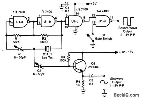
Using a Quad NAND Gate, the TTL oscillator can use fundamental crystals between 1 and 10 MHz. The sine-wave output is taken directly from the crystal, which acts as its ovrn filter, and yields a fairly clean sine wave. Adjust C1 and C2 for the best sine wave and also to set the crystal frequency. TTL square wave can be taken from U1D. The gate switch can be replaced with a Iogic gate to electronically control the output. (View)
View full Circuit Diagram | Comments | Reading(7029)
315_KC_CRYSTAL_OSCILLATOR
Published:2009/7/19 23:58:00 Author:Jessie
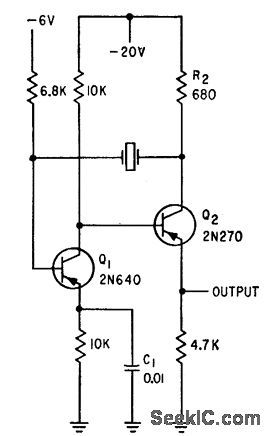
Provides sync signals for tv camera sweeps. Crystal vibrates in lowest-frequency natural mode of long thin bars, resulting in high impedance and difficulty in exciting crystal, and making it necessary to use two transistors in symmetrical collector-coupled mvbr oscillator.-D. G. Cartoon, Designing Transistorized Television Cameras, Electronics, 33:37, p 72-75. (View)
View full Circuit Diagram | Comments | Reading(768)
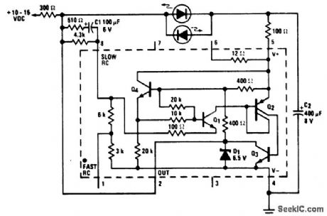
12_volt_two_wire_automotive_flasher_using_an_LM3909_chip
Published:2009/7/19 23:57:00 Author:Jessie
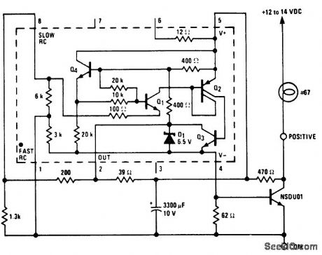
12-volt two-wire automotive flasher using an LM3909 chip. Circuitry inside dashes is the LM3909. Rate is about 1 hertz. Since it is a two-wire circuit it can be adapted for either negative or positive ground systems. In positive ground systems place the lamp between the common and the negative battery terminal (courtesy National Semiconductor Corporation). (View)
View full Circuit Diagram | Comments | Reading(1644)
30_MC_LINEAR_SINGLE_SIDEBAND_AMPLIFIER
Published:2009/7/10 1:31:00 Author:May

Single silicon transistor with impedance matching network and pi output network delivers 20 w of r-f peak envelope power, with all odd-order distortion products at least 30 db down.-R. C. Heihall, Getting Transistors Into Single,Sideband Amplilers, Elecrronics, 37:17, p 72-75. (View)
View full Circuit Diagram | Comments | Reading(768)
SIGNAL_INJECTOR_1
Published:2009/7/10 1:30:00 Author:May
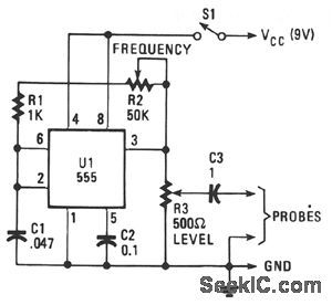
The unit provides a square-wave output that is rich in harmonic content. The circuit's output frequency can be varied from 50 Hz to 15 kHz. The heart of the circuit is a 555 astable connected in its equal mark/space mode. The frequency is controlled by potentiometer R2 and capacitor C1.Resistor R3 controls the output level with the output ac-coupled through C3.
(View)
View full Circuit Diagram | Comments | Reading(955)
AIRBORNE_TV_SUNSPOT_CAMERA
Published:2009/7/19 23:57:00 Author:Jessie
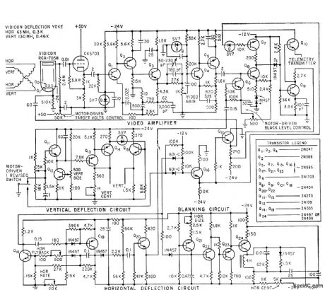
Used with slow-scan iv system for high-altitude solar photography from balloon. Uses 500cps horizontal scan without interlace for 500-line resolution, requiring 200-kc band. width. Video output of camera goes to 2-w commercial 225.7.Mc f-m telemetry transmitter exciting 10.w power stage.-L. E. Flory el al., Television System for Stratoscope I, Electronics, 33:25, p 49-53.
(View)
View full Circuit Diagram | Comments | Reading(1246)
LOW_FREQUENCY_SINE_WAVE_GENERATOR
Published:2009/7/10 1:30:00 Author:May
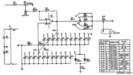
Using a Wien-bridge oscillator, this circuit generates switch-selected frequencies from 1 to 20 Hz. A 741 op amp is used as the active element. (View)
View full Circuit Diagram | Comments | Reading(1907)
SAWTOOTH_CONVERTER
Published:2009/7/10 1:30:00 Author:May
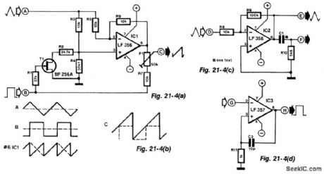
Simple function generators normally provide sinusoidal, rectangular, and triangular waveforms, but seldom a sawtooth. The circuit in Fig. 21-4(a) derives a sawtooth signal from a rectangular and triangular signal. Its quality depends on the linearity of the triangular signal, the slope of the edges of the rectangular signal and the phase relationship between the rectangular and triangular signals.
The conversion is carried out in IC1. Whether the triangular signal at input A is converted or not by IC1 depends on the state of T1. This FET is controlled by the rectangular signal at input B.
The signal at the output of the op amp is a sawtooth (see Fig. 21-4(b)) whose trailing edge is inverted. The frequency of this signal is double that of the input signals.
If in this state, the dc level of each inverted edge is raised sufficiently to make the lower level of that edge coincide with the higher level of the preceding edge, a sawtooth signal of the same frequency (but double the peak value of the input signals) is obtained. The dc level is raised by adding input B to the output of IC1 via R7 and P1. The preset should preferably be a multiturn type. Resistors R2 and R4 are 1% types.
If a rectangular signal is not available, or if its peak value is too small, the auxiliary circuits (shown in Figs. 21-4(c) and 21-4(d)) will be found useful. Figure 21-4(g) amplifies the triangular input at A by 10. Differentiating network C1/R10 derives rectangular pulses from the amplified triangular signal and these are available at F.
The pulses at F are shaped by the circuit in Fig. 21-4(d) to rectangular signals that have the same peak value as the supply voltage. Capacitor C2 increases the slope of the edge; it can be omitted for low-frequency signals.
The converter provides sawtooth signals over the frequency range of 15 Hz to 15 kHz. If the auxiliary circuits are used, capacitor C1 must be compatible with the frequency of the sawtooth signal (its value lies between 2 nF and 100 pF). The supply for all circuits can be between ±10 V and ±15V. Each op amp draws a current of 4 to 6 mA. (View)
View full Circuit Diagram | Comments | Reading(1492)
Automatic_flasher_light_for_use_around_marine_buoys_piers_or_towers
Published:2009/7/19 23:54:00 Author:Jessie
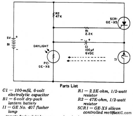
Automatic flasher light for use around marine buoys, piers, or towers. It starts working at dark and stops at dawn. When constructing this circuit be sure to place the photoresistor so that it receives as much light as possible without interfering with the flasher light (courtesy General Electric Company). (View)
View full Circuit Diagram | Comments | Reading(624)
SIGNAL_INJECTOR
Published:2009/7/10 1:29:00 Author:May
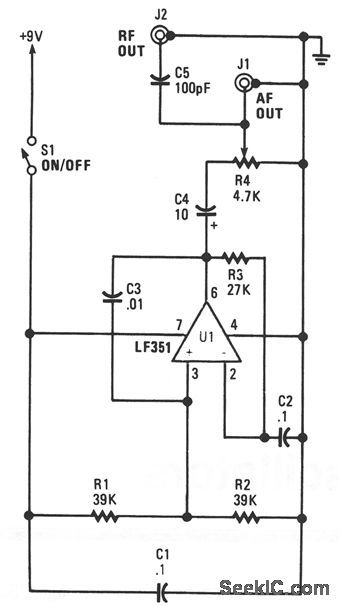
This unit is a single oscillator built around an LF351 JFET-input op amp. Resistors R1 and R2 bias the noninverting input while R3 biases the inverting input from the output. This layout provides 100% negative feedback, but the decoupling caused by C2 gives reduced feedback and high-voltage gain when dealing with audio frequencies. The fundamental operating frequency is about 800 Hz. Potentiometer R4 is the output-level control. To use it start at the speaker. If no tone is heard, move back to the amplifer input, and listen for the tone. Still if no tone is heard, continue backtracking from the output to the input, covering all stages in between. The stage where the signal is lost is the one that is not operating. (View)
View full Circuit Diagram | Comments | Reading(1490)
APERTURE_CORRECTING_CIRCUIT
Published:2009/7/19 23:54:00 Author:Jessie
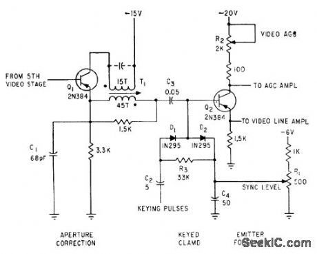
Diode D2 of keyed clamp acts as conventional peak rectifier d-c restorer for tv camera circuif. -D. G. Cartoon, Designing Transistorized Television Cameras, Electronics, 33:37, p 72-75. (View)
View full Circuit Diagram | Comments | Reading(799)
NUVISTOR_TRANSISTOR_CASCODED_TV_CAMERA_PREAMP
Published:2009/7/19 23:53:00 Author:Jessie
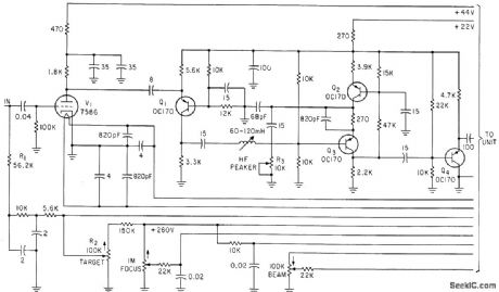
Noise figure is 3 db and video bandwidth about 6 Mc. Used with uvicon camera tube for ultraviolent telescope,-R. N. Riggs, Ultraviolet Space Telescope Will Scan the Stars, Electronics, 35:46, p 37-43. (View)
View full Circuit Diagram | Comments | Reading(977)
WIEN_BRIDGE_OSCILLATOR_1
Published:2009/7/10 1:29:00 Author:May
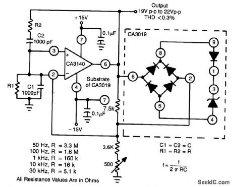
This circuit makes excellent use of high input impedance, high slew rate, ties of CA3140 BiMOS op amp, in combination with CA3019 diode array. (View)
View full Circuit Diagram | Comments | Reading(0)
ELECTRONIC_DOORBELL
Published:2009/7/10 1:29:00 Author:May
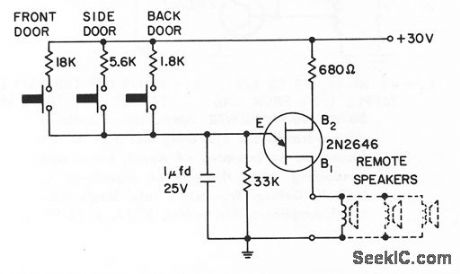
Single unijunctfon transistor oscillates at different tone for each door.- Tronsislor Manucl, Seventh Edition, General Electric Co., 1964, p 380.
(View)
View full Circuit Diagram | Comments | Reading(609)
| Pages:853/2234 At 20841842843844845846847848849850851852853854855856857858859860Under 20 |
Circuit Categories
power supply circuit
Amplifier Circuit
Basic Circuit
LED and Light Circuit
Sensor Circuit
Signal Processing
Electrical Equipment Circuit
Control Circuit
Remote Control Circuit
A/D-D/A Converter Circuit
Audio Circuit
Measuring and Test Circuit
Communication Circuit
Computer-Related Circuit
555 Circuit
Automotive Circuit
Repairing Circuit