
Circuit Diagram
Index 848
Trigger_switch_flasher
Published:2009/7/19 23:22:00 Author:Jessie
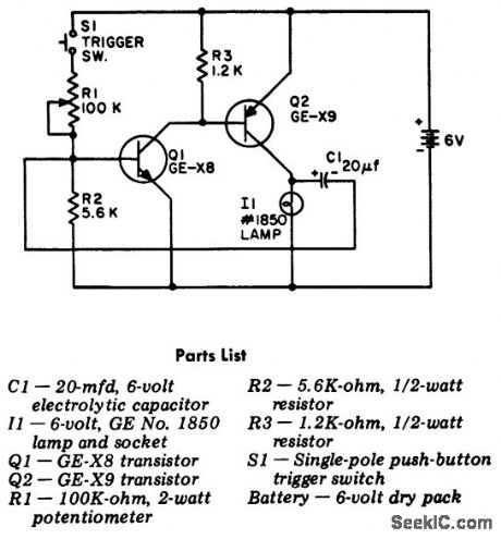
Trigger switch flasher. The flasher circuit is activated whenever pushbutton switch S1 is pressed. The circuit is a two-stage direct-coupled amplifier working as a multivibrator (courtesy General Electric Company). (View)
View full Circuit Diagram | Comments | Reading(997)
Latch_circuit
Published:2009/7/19 23:22:00 Author:Jessie
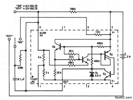
In this application, the LM3909 switches to, and holds its condition, whenever the switch changes sides-even if the contact is momentary. This results in an output that remains in the 0.3-V (on) or 2.9-V (off) condition. (View)
View full Circuit Diagram | Comments | Reading(77)
LIGHT_TRANSMTTER
Published:2009/7/10 1:59:00 Author:May
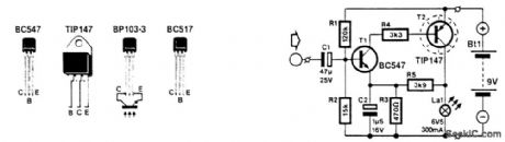
This circuit modulates the current through a lamp filament. Use a low-voltage lamp with a thin, straight filament. They have a fast response to ftlament voltage variations. dc is applied to bias the fila-ment that is on, and the audio is superimposed. A BC457 drives a TIP147, which modulates the filament current. (View)
View full Circuit Diagram | Comments | Reading(3902)
SATURABLE_REACTOR_OSCILLATOR
Published:2009/7/19 23:21:00 Author:Jessie
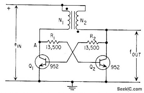
Timebase integration of a variable is performed by counting cycles of saturable-reactor oscillator whose frequency is proportional to the variable. linearity is within 1% of full scale.-L. W. Langley, Saturable-Core Oscillator Integrates Gas-Flow Data, Electronics, 32:4, p 42-43. (View)
View full Circuit Diagram | Comments | Reading(1188)
WHOOPER
Published:2009/7/10 1:58:00 Author:May
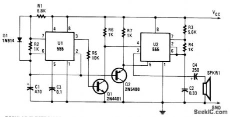
Integrated circuit U1 is connected as a low-frequency asymmetrical oscillator. Its output is inverted by Q1 and fed to the reset terminal of U2 at pin 5. Integrated circuit U2 is configured as an audio oscillator and is enabled when the output of UI is low. With the voltage at pin 5 of U2 constant, the circuit just bleeps. The voltage across capacitor C1 is fed to the base of Q2, which turns it on and grounds pin 5 of U2. When the frequency of the reset signal on pin 4 falls, the output frequency of U2 rises. The output then becomes a whoop, starting low in frequency and ending high. Resistor R1 sets the repetition rate and R2 determines the time duration of the whoop. Resistors R3 and R4 set the center-operating frequency. (View)
View full Circuit Diagram | Comments | Reading(1685)
MAGNETICALLY_CONTROLLED_IRANSISTOR
Published:2009/7/10 1:58:00 Author:May
Uncapped pnp germanium alloy junction transistor placed in strong mognetic leld shows gain variation with fiux density, with direcion and amount of gain depending on direction of magnetic leld.-R. W. Lade et al., 37:31, Magnetic Fields Vary Transistor Goin, Electronics, 34:5, p 68-70. (View)
View full Circuit Diagram | Comments | Reading(621)
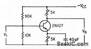
50_MEG_INPUT_IMPEDANCE
Published:2009/7/10 1:58:00 Author:May
Feedback from Q2 to let Q1 boosts input impedance.-B.Down, Using Feedback in FET Circuit to Reduce Input Capacitance, Electronics,p 63-65. (View)
View full Circuit Diagram | Comments | Reading(768)
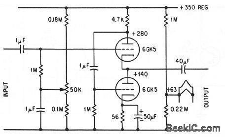
STEAM_TBAIN_WITH_WHISTLE
Published:2009/7/10 1:57:00 Author:May
View full Circuit Diagram | Comments | Reading(758)
30_MC_LOW_NOISE
Published:2009/7/10 1:57:00 Author:May

Noise figure is only 4 db for generator resistance of 200 ohms.-D. Hall, Using Epitaxial Transistors in Switching and R-F Circuits, Electronics, 34:13, p 52-53. (View)
View full Circuit Diagram | Comments | Reading(544)
MAGNETIC_FIELD_METER
Published:2009/7/10 1:56:00 Author:May
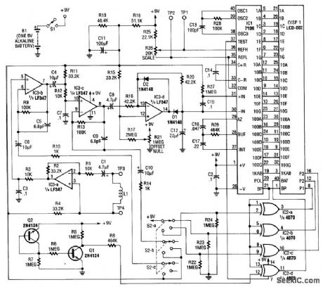
Using a pickup coil to drive an amplifier (IC3A-B-C-D), this meter circuit can be directly calibrated in field-intensity units. R3/C3 and R12/C7 establish a frequency roll off that compensates for the pickup-coil sensitivity, and set a 20-kHz cut-off point. S2 is the range-select switch. L1 is an 18-turn 3 diameter coil.The frequency range is 50 Hz to 20 kHz and the range of measurement is 0.1 to 20000 microlbsiers (μT). (View)
View full Circuit Diagram | Comments | Reading(1175)
TWO_STATE_SIREN
Published:2009/7/10 1:56:00 Author:May
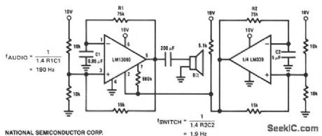
This is a two-state or on/off-type siren where the LM13080 oscillates at an audio frequency and drives an 8-0 speaker. The LM339 acts as a switch which controls the audio burst rate. (View)
View full Circuit Diagram | Comments | Reading(1614)
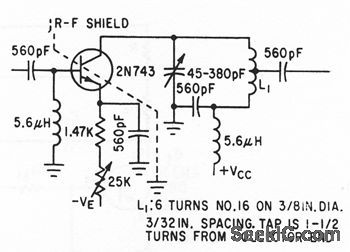
SMALL_SIGNAL_60_MC
Published:2009/7/10 1:56:00 Author:May
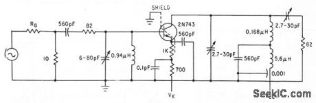
Epitaxial 2N743 is operated Gammon-emitter at signal frequency and Gammon-base for biasing. Unneufralized gain per stage is 17 db.-D. Hall, Using Epitaxial Transistors in Switching and R.F Circuits, Electronics, 34:13, p 52-53. (View)
View full Circuit Diagram | Comments | Reading(621)
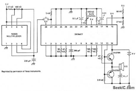
LOW_COST_SIREN
Published:2009/7/10 1:55:00 Author:May
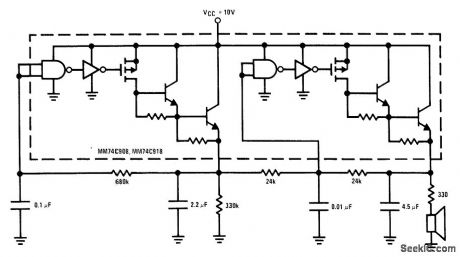
This low-cost 1-package siren has one VCO, and the other oscillator generates the voltage ramp to vary the frequency at the VCO output. All components within the dotted line are part of the IC. (View)
View full Circuit Diagram | Comments | Reading(837)
VOLTAGE_TO_CURRENT_CONVERTER
Published:2009/7/10 1:55:00 Author:May
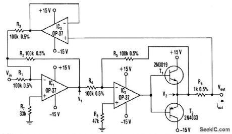
This voltage to current converter uses three op amps to drive a pair of power transistors. The current output is calculated as:
IOUT=Vin/R6
Output resistance is over 50 MΩ. IOUT can range from 1 mA to the current ratings of T1 and T2. (View)
View full Circuit Diagram | Comments | Reading(6754)
SIREN
Published:2009/7/10 1:55:00 Author:May
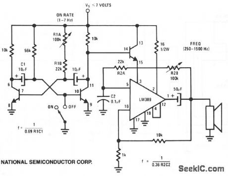
This circuit uses one of the LM389 transistors to gate the power amplifier on and off by applying the muting technique. The other transistors form a cross-coupled multivibrator circuit that controls the rate of the square-wave oscillator. The power amplifier is used as the square-wave oscillator with individual frequency adjust provided by potentiometer R2B. (View)
View full Circuit Diagram | Comments | Reading(2479)
60_MC_LOW_NOISE
Published:2009/7/10 1:55:00 Author:May
Noise figure is only 6 db for generator resistance of 150 ohms.-D. Hall, Using Epitaxial Transistors in Switching and R-F Circuits, Electronics, 34:13, p 52-53. (View)
View full Circuit Diagram | Comments | Reading(556)
OPTICAL_RECEIVER
Published:2009/7/10 1:54:00 Author:May
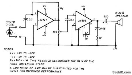
An optical receiver for light-wave communications, this circuit works with AM-type light signals. (View)
View full Circuit Diagram | Comments | Reading(3489)
CASCODE_FOLLOWER
Published:2009/7/10 1:54:00 Author:May
Output is 20 v peak-to-peak into 1,000 ohms, down to 5 cps, with high stability.-R. W. Johnson, Circuit with a Twist: The cascode 36:49,p 69-70. (View)
View full Circuit Diagram | Comments | Reading(812)
dc_dc_CONVERTER
Published:2009/7/10 1:53:00 Author:May
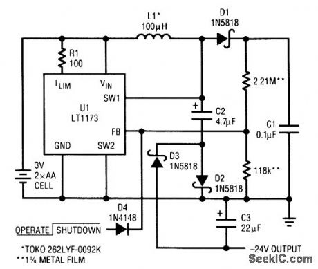
This circuit uses a Linear Technology LT1073 in a -24-V converter. The supply can be two AA cells (3 V) or 5 V. The circuit can deliver 7 mA. (View)
View full Circuit Diagram | Comments | Reading(3684)
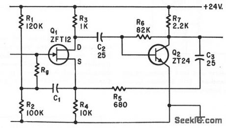
6_W_WARBLE_TONE_SIREN
Published:2009/7/10 1:53:00 Author:May

This circuit uses a CMOS chip and a VMOS FET amplifier for 6 W of audio output. 18 W of audio canbe generated usmg a+24-Vdc supply, IC1A and IC1B are used as a 1-Hz oscillator. IC1C and IC1D form a 1-kHz multivibrator that is gated by the 1-Hz signal from IC1A and IC1B. (View)
View full Circuit Diagram | Comments | Reading(1415)
| Pages:848/2234 At 20841842843844845846847848849850851852853854855856857858859860Under 20 |
Circuit Categories
power supply circuit
Amplifier Circuit
Basic Circuit
LED and Light Circuit
Sensor Circuit
Signal Processing
Electrical Equipment Circuit
Control Circuit
Remote Control Circuit
A/D-D/A Converter Circuit
Audio Circuit
Measuring and Test Circuit
Communication Circuit
Computer-Related Circuit
555 Circuit
Automotive Circuit
Repairing Circuit