
Circuit Diagram
Index 844
TUNED_10_MC_AMPLIFIER_WITHOUT_NEU_TRALIZATION
Published:2009/7/10 2:18:00 Author:May
Low reverse transfer of cascade connection makes possible stable operation of commonsource fet. Transducer gains are 20.6 db and 25.3 db for 2N2497 and 2N2499 respectively.-Texas Instrumens Inc., Solid-State Communications, Mc Graw-Hill, N.Y., 1966, p 142. (View)
View full Circuit Diagram | Comments | Reading(738)
SIMPLE_THIRD_OVERTONE_OSCILLATOR
Published:2009/7/10 2:18:00 Author:May
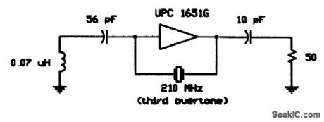
Using a 210-MHz third overtone crystal,this circuit operates directly at the crystal frequency,with210-MHz output and no multiplier stages. (View)
View full Circuit Diagram | Comments | Reading(657)
8748_to_8251_interface
Published:2009/7/19 22:56:00 Author:Jessie
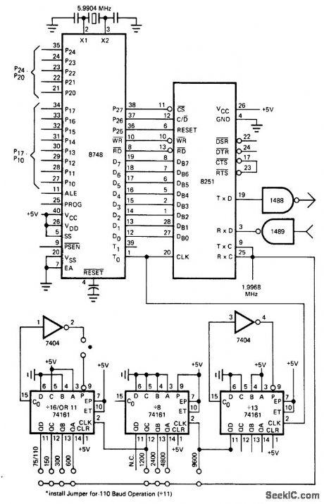
8748 to 8251 interface. The 8748 is an MCS-48 processor and the 8251 is a USART (courtesy Intel Corporation). (View)
View full Circuit Diagram | Comments | Reading(2268)
SLAVED_DUAL_TRACKING_REGULATOR
Published:2009/7/19 22:55:00 Author:Jessie
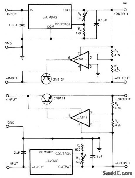


Uses Fairchild μA78MG adjustable four-terminal regulator with opamp and power transistor for delivering output currents up to 0.5 A per side, with output voltages adjustable from ±5V to ±20V for component values shown.. Positive side functions independently of negative side, but negative output is slave of positive output.To slave positive side, use μA79MG and 2N6121 NPN transistor as at (b). Opamp functions as inverting amplifier driving power transistor serving as series-pass element for opposite side of regulator, with R1 adjusting both output volt-ages simultaneously.-A. Adamian, Dual Adjustable Tracking Regulator Delivers 0.5A/Side, EDN Magazine, Jan, 5, 1977, p 42. (View)
View full Circuit Diagram | Comments | Reading(1269)
BIKE_SPEEDOMETER
Published:2009/7/10 2:18:00 Author:May
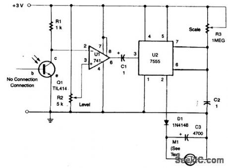
A TIL414 photo transistor senses reflection from a spoke-mounted reflector. This generates a pulse and sends it to U1 and U2, a monostable multi ibrator, which drives meter M1. (View)
View full Circuit Diagram | Comments | Reading(1249)
12_V_flasher
Published:2009/7/19 22:55:00 Author:Jessie
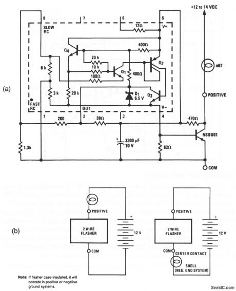
This LM3909 flasher circuit can be powered from an automotive storage battery, provides a 1-Hz flash, and can power a 600-mA lamp. A particular advantage of this circuit is that only two external wires are required (Fig. 12-50B), Also, no circuit failure can cause a battery drain greater than that of the #67 lamp.National Semiconductor, Linear Applications Handbook, 1991, p. 398. (View)
View full Circuit Diagram | Comments | Reading(942)
SIMPLE_FUNDAMENTAL_CRYSTAL_oscILLATOR
Published:2009/7/10 2:17:00 Author:May
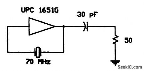
This simple fundamental oscillator uses a μPC1651G IC and two components. The crystal is funda-mental. (View)
View full Circuit Diagram | Comments | Reading(685)
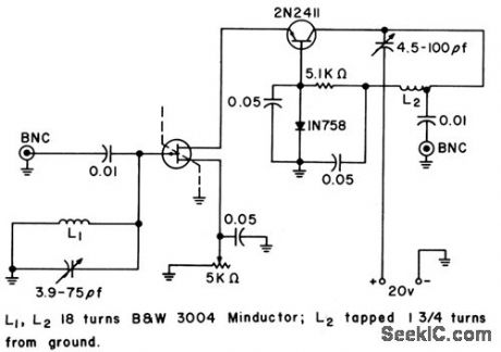
ANTENNAFIER
Published:2009/7/19 22:55:00 Author:Jessie
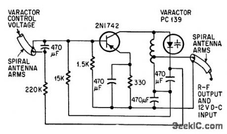
Varactor-tuned transistor amp lifer bulb into tip of conical spiral antenna is tuned from 120 to 240 Mc by varying varactor voltage from 0 to 40 v d-c.-J. F. Rippin, Making the Antenna an Active Part-net, Electronics, 38:16, p 93-96. (View)
View full Circuit Diagram | Comments | Reading(754)
100_MEG_INPUT_IMPEDANCE
Published:2009/7/10 2:17:00 Author:May
Variation of Darlington connection gives low-noise amplifier with high input impedance. Thermal and shot noise are much lower than ficker, leakage, and surface noise.-I. Levine, High Input Impedance Transistor Circuits, Fleetronics, 33:36, p 50-52. (View)
View full Circuit Diagram | Comments | Reading(798)
ELECTRONIC_BAGPIPE
Published:2009/7/10 2:17:00 Author:May
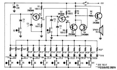
The electronic bagpipe mimics the sound of real instruments. This circuit uses two UJT oscillators and an amplifier (Q3, Q4, and Q5). R7 through R22 are selected for tonal range desired (typically 3300 Ω). Each key selects resistors for the two oscillator circuits Q1 and Q2. S2 and S3 vary the tonal range of S4 through S11. (View)
View full Circuit Diagram | Comments | Reading(0)
Mini_strobe_variable_flasher
Published:2009/7/19 22:53:00 Author:Jessie
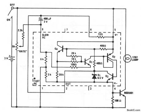
This LM3909 flasher circuit can be used as a variable-rate warning light, or for advertising or special effects. The rate control can adjust from no flashes to a continuous on. The miniature 1767 lamp can be flashed several times per second. As a toy, the flashing rate can be adjusted to mimic the strobes at rock concerts or the flicker of old-time movies. In a dark room, the flashes are almost fast enough to stop a person's motion. National Semiconductor Linear Applications Handbook 1991 p 397
(View)
View full Circuit Diagram | Comments | Reading(1165)
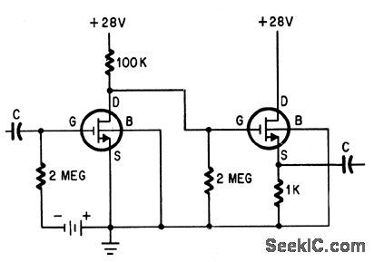
MOS_FET_WITH_NPN
Published:2009/7/10 2:16:00 Author:May
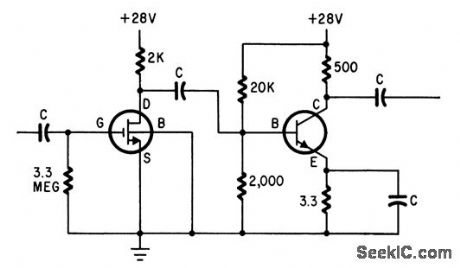
FET input stage serves as high-to-low impedance transformer for power transistor and gives very high power gain.-D. M. Griswold, Understdnding and Using the MOS FET, Electronics, 37:31, p 66-70. (View)
View full Circuit Diagram | Comments | Reading(899)
BROADBAND_AC_ACTIVE_RECTIFIER
Published:2009/7/10 2:16:00 Author:May
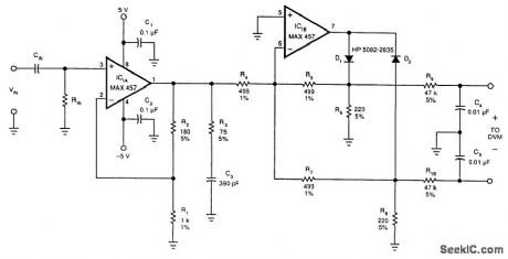
This circuit converts sine waves of up to 1-V rms into an equivalent dc level. It should prove useful as an ac broadband voltmeter. IC1 is an input amplifier that converts level from rms to an equivalent dc level and feeds ICB1. R3 and C3 are stabilizing components. IC2 acts as a full-wave rectifier. R6, R5, and D1 rectify positive levels, R7, R8, and D2 negative-going signals. R9, R10, C4, and C5 are low-pass filters.The output can feed a DVM or another meter. (View)
View full Circuit Diagram | Comments | Reading(1084)
DIRECTLY_COUPLED_MOS_FET
Published:2009/7/10 2:16:00 Author:May
Eliminates coupling capacitors but requires additional bias supply.-D. M. Griswold, Understanding and Using the MOS FET, Electronics, 37:31, p 66-70. (View)
View full Circuit Diagram | Comments | Reading(610)
460_KC_F_M_RECEIVER_FOR_WIRELESS_MICRO_PHONE
Published:2009/7/19 22:52:00 Author:Jessie
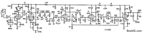
Loop 5 meters square picks up in duction field of four-transmitter and feeds r-f amplifier V1. Operating frequency is converted to 50 kc by V2 and amplified and limited by V3 and V4. Audio signal is recovered after passing through, low-pass filter. Peak audio output is about 0.5 v, enough to feed p-a or speech preamplifier-G. F, Montgomery, Wireless Microphone use F-M Modulation, Electronics, 31:1, p 54-55. (View)
View full Circuit Diagram | Comments | Reading(728)
SIMPLE_PHOTOELECTRIC_LIGHT_CONTROLLER
Published:2009/7/10 2:15:00 Author:May
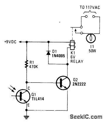
A phototransistor senses daylight. At dusk, it ceases to conduct and R1 biases Q2, activates K1, and switches on the light. At dawn, Q1 starts to conduct, and Q2 is cut off. K1 drops out and the light goes out. (View)
View full Circuit Diagram | Comments | Reading(821)
VOLTAGE_CONTROLLED_ATTENUATOR
Published:2009/7/10 2:15:00 Author:May
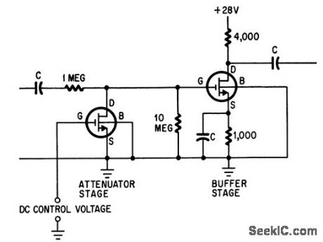
Can attenuate input signals 70 db when mos let is followed by high-impedance load such as common-source mos fet amplifier.-D. M. Gris-wold, Understanding and Using the MOS FET, Electronics, 37:31, p 66-70. (View)
View full Circuit Diagram | Comments | Reading(0)
Safe_high_voltage_flasher_or_monitor
Published:2009/7/19 22:51:00 Author:Jessie
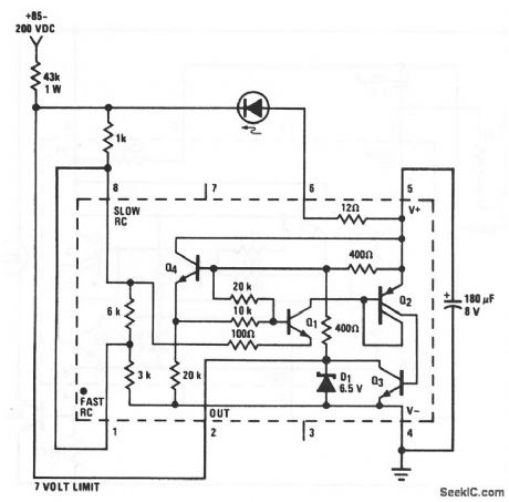
A high-voltage (85 to 200 V) power supply can be monitored at a remote location safely and with little current drain using this LM3909 circuit. If the 43-kΩ dropping resistor is located at the source end, voltages to the LED and LM3909 are limited to loss than 7 V above ground. A chart outlining operation of this circuit at various voltages appears on the LM3909 data sheet. (View)
View full Circuit Diagram | Comments | Reading(859)
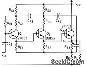
NONLINEAR_FEEDBACK_LOOP
Published:2009/7/10 2:14:00 Author:May
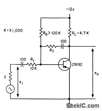
Type WE41A copper-oxide varistor for Rf in feedback loop gives radically different voltage-gain charctcteristic than silicon diode for Rf, but both give exponential response and increase dynamic range.-J. C. Looney, Designing Amplifiers with Nonlinear Feedback, Electronics, 34:13, p 46-49. (View)
View full Circuit Diagram | Comments | Reading(676)
LOW_SUPPLY_VOLTAGE_VHF
Published:2009/7/10 2:13:00 Author:May
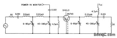
Good high-frequency parameters of epitaxial mesa transistor give high gain and efficiency at supply voltage of only 12 v. Output is 0.5 w ct 70 Mc.-D. Hall, Using Epitaxial Transistors in Switching and R-F Circuits, Electronics, 34:13, p 52-53. (View)
View full Circuit Diagram | Comments | Reading(550)
| Pages:844/2234 At 20841842843844845846847848849850851852853854855856857858859860Under 20 |
Circuit Categories
power supply circuit
Amplifier Circuit
Basic Circuit
LED and Light Circuit
Sensor Circuit
Signal Processing
Electrical Equipment Circuit
Control Circuit
Remote Control Circuit
A/D-D/A Converter Circuit
Audio Circuit
Measuring and Test Circuit
Communication Circuit
Computer-Related Circuit
555 Circuit
Automotive Circuit
Repairing Circuit