
Circuit Diagram
Index 846
28V_AT_7A
Published:2009/7/19 22:44:00 Author:Jessie
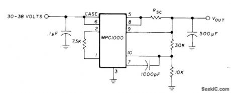
Uses Motorola MPC1000 positive voltage regulator to provide regulated voltage for aircraft radio equipment being used at ground station. Current-limiting resistor RSC is in range of 0.66 to 0.066 ohm. Use copper wire about 50% longer than calculated length and shorten step by step until required pass current is obtained; thus, start with 25 ft of No. 16, 15 ft of No. 18, 10ft of No. 20, or 6ft of No. 22. Input voltage is obtained from 30-V transformer and bridge rectifier.-G. L. Tater, The MPC1000-Super Regulator, Ham Radio, Sept. 1976, p 52-54. (View)
View full Circuit Diagram | Comments | Reading(865)
ELEKTOR_ELECTRONICS
Published:2009/7/10 2:08:00 Author:May
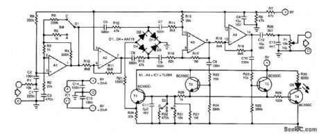
The control of this compressor is based on the dependence of the dynamic resistance of a diode on the current flowing through it. The heart of the present circuit is the diode bridge (D1 through D4), which behaves as a variable resistance controlled by the current flowing in T1.The input signal is applied to preamplifier state A1 via low-pass filter R1/C1 that removes any HF noise from the input.Switch S1 in the feedback loop of A1 sets the amplification to 1 (position A), 6 (C) or 11 (B). The amplified signal is applied directly to the diode bridge via R12 and C5, and inverted via inverter A2, capacitor C6 and resistor R13.The two signals are summed by the bridge, amplified (in A3), then split again into two, one of which is inverted by A4. The positive half cycles of the two signals are used to switch on T2 and T3, respectively. Capacitor C11 is then charged via R12. When the potential across this capacitor reaches a certain level, T1 is also switched on, after which a control current flows through the bridge via R21. This current lowers the resistance of the bridge so that the signal is attenuated (compressed). At the same time, the LED lights to indicate that the signal is being compressed. Capacitor C12 prevents any dc voltage from reaching the output.The output signal is taken from the wiper of P1. Low-pass section R20/C13 limits its bandwidth to 12 kHz. Switch S2 enables the selection of various decay times from C11. The values shown in the diagram are the most useful. Nevertheless, these values are subjective and can be altered to personal taste and requirements.
(View)
View full Circuit Diagram | Comments | Reading(2428)
PRECISION_FULL_WAVE_ac_dc_CONVERTER
Published:2009/7/10 2:08:00 Author:May
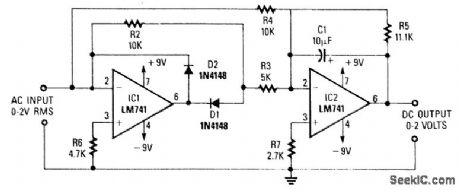
A dc level is produced that corresponds to the ac input rms value (if sine wave). R1/C5 set the gain of IC2 to 1.11. This factor is the average-to-rms conversion factor. IC1 and IC2 act as a full-wave rectifier circuit, with D1 and D2. (View)
View full Circuit Diagram | Comments | Reading(2163)
Low_power_flashers
Published:2009/7/19 22:43:00 Author:Jessie
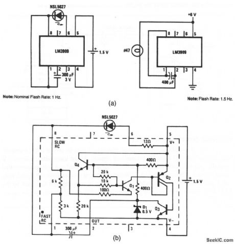
This circuit shows two simple flashers that use an LM3909. Figure 12-43B shows the internal circuit. Notice that the LM3909 requires only 1.5 V.However, 6 V is required when the LM3909 must drive a #47 lamp (or any similar load), instead of an LED. The flashing rate is determined by the value of the capacitor between pins 1 and 2. Iffiioo8l Semiconductor Linear Applications Handbook, 1991 p 394 (View)
View full Circuit Diagram | Comments | Reading(923)
FET_MICROPOWER
Published:2009/7/10 2:08:00 Author:May
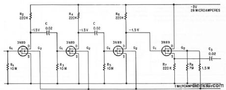
Voltage gain is 60 db from 1 cps to 30 kc, with O.5 v rms maximum output voltage, for power drain under l00 microwatts. First three transistors should be matched.-J. S. Sherwin, An FET Micropower Amplifier, Electtonics, 37:31, p 74-75. (View)
View full Circuit Diagram | Comments | Reading(655)
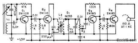
FIVE_TRANSISTOR_AUTO_RADIO
Published:2009/7/19 22:42:00 Author:Jessie
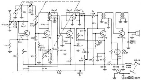
Q1 is r-f amplifier, Q2 is autodyne converter, Q3 is unneutralized 262-kc i-f amplifier or, D1 is audio detector Q4 is audio driver, and Q5 is single-ended output delivering 4 w at less than 10% total distortion. Sensitivity is 2 microvolts at 1 w audio output.-R. A. Santilli and C. F. Wheatley, Transistorizing Automobile Broadcast Receivers, Electronics, 32:38, P 42-45.
(View)
View full Circuit Diagram | Comments | Reading(2194)
MODIFIED_EMITTER_SQUARED_EOLLOWER
Published:2009/7/10 2:07:00 Author:May
Complementary transistor arrangement of feedback amplifier is modiled to reduce shunting effect of R3 by applying positive feedback voltage that artificially increases vctlue of R3.-T. K. Hemingway and J. Willis, Transistor Pairs Improve Emitter-Follower Performance, Electronics, 35:21, p 48-49. (View)
View full Circuit Diagram | Comments | Reading(749)
SINE_WAVE_SQUARE_WAVE_CONVERTER
Published:2009/7/10 2:07:00 Author:May
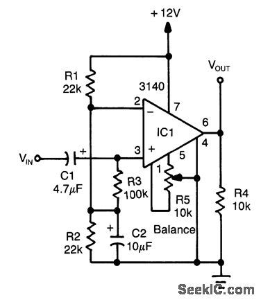
An op amp used as a comparator produces a 10-V p-p square-wave output with 100-mV input, to 15 kHz. Adjust R5 for symmetry of square wave at low input levels. (View)
View full Circuit Diagram | Comments | Reading(3245)
Remotely_powered_sensor_amp
Published:2009/7/19 22:41:00 Author:Jessie
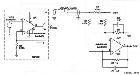
A simple two-wire current transmitter uses no power at the transmit-ting end (except that from the transmitted signal). At the transmitter, a 0- to 1-V input drives a MAX406 and npn transistor that is connected as a voltage-controlled current source. Although the MAX406 supply current is taken from the signal, only 1-μA out of 2-mA error is added. The output is sent through the coax to the MAX480, which reconstructs a ground-referenced 0- to 1-V signal. Maxim 1992, Applications and Product Highlights p. 5-9 (View)
View full Circuit Diagram | Comments | Reading(701)
DIGITAL_TACHOMETER_CIRCUITRY
Published:2009/7/10 2:06:00 Author:May
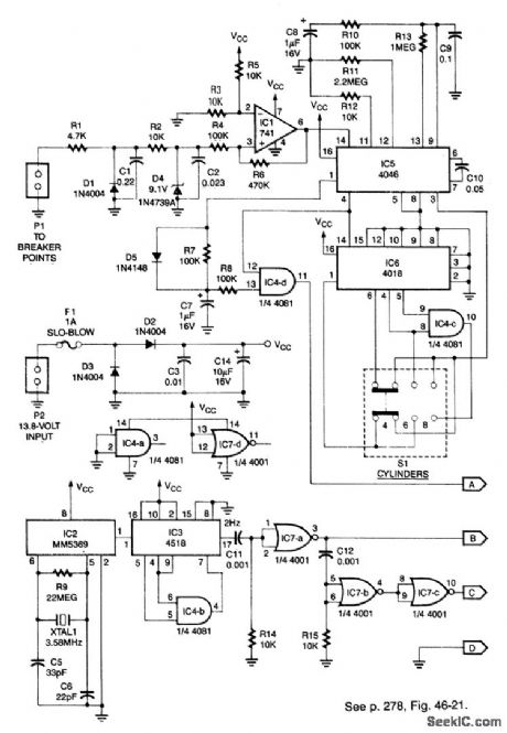
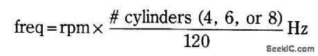
This system can be used with 4-, 6-, or 8-cylinder automobiles. The timebase formed by IC5 is an oscillator that drives counter IC6, which divides by 6, 4, or 3 for 4-, 6-, or 8-cylinder engines, respectively.S1 selects this number IC5 produces a signal that is phaselocked to this multiple of the ignition system frequency, which in turn depends on engine speed.
ICl conditions the ianition input at PI to feed IC5. The output of IC4D, which is the same frequency as the VC0 in IC5, is fed to the frequency display.
IC2 generates a 60-Hz sianal using a 3.58-MHz reference. IC3 and IC4B divide this by 30 to produce 2Hz. IC7B/IC7C and C12/R15 produce a delayed 2-Hz signal. These sianals are fed to the counter circuit. (View)
View full Circuit Diagram | Comments | Reading(1676)
SC_MP_to_cassette_tape_recorder_interface
Published:2009/7/19 22:40:00 Author:Jessie
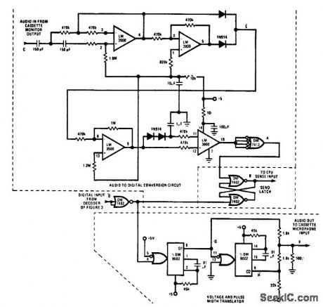
SC/MP to cassette tape recorder interface (courtesy National Semiconductor Corporation). (View)
View full Circuit Diagram | Comments | Reading(850)
Buffered_pH_probe_allows_low_cost_cable
Published:2009/7/19 22:40:00 Author:Jessie
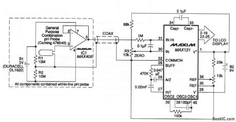
The probe circuit eliminates expensive low-leakage cables that often connect pH probes to meters. A MAX406 and a lithium battery are included in the probe housing. A conventional low-cost coax carries the buffered pH signal to the MAX131 A/D converter. The battery life depends on the dc loading of the amplifier output (MAX131 input current and cable leakage). In most cases, battery life exceeds the functional life of the probe. Maxim, 1992, Applications and Product Highlights p 5-9 (View)
View full Circuit Diagram | Comments | Reading(829)
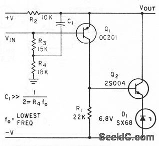
12_V_LATCH
Published:2009/7/10 2:06:00 Author:May
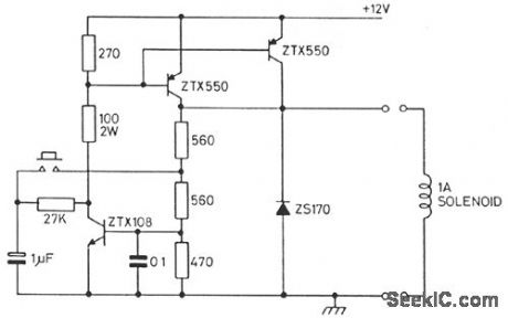
This circuit controls a solenoid by the operation of a single push-button switch. The circuit will supply loads of over 1 A and can be operated up to a maximum speed of once every 0.6 second. When power is first applied to the circuit, the solenoid will always start in its off position. Other features of the circuit are its automatic turn-off, if the load is shorted, and its virtually zero-power consumption when off. (View)
View full Circuit Diagram | Comments | Reading(859)
LIGHT_DETECTOR
Published:2009/7/10 2:06:00 Author:May

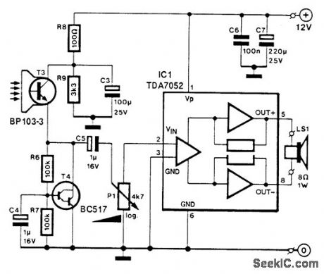
T3 is a photocell or phototransistor. T4controls the emitter voltage of T3. IC1 is an audio amplifier to provide amplification of the signal from the photocell. (View)
View full Circuit Diagram | Comments | Reading(789)
FIXED_GAIN_ANTENNAFIER
Published:2009/7/19 22:39:00 Author:Jessie
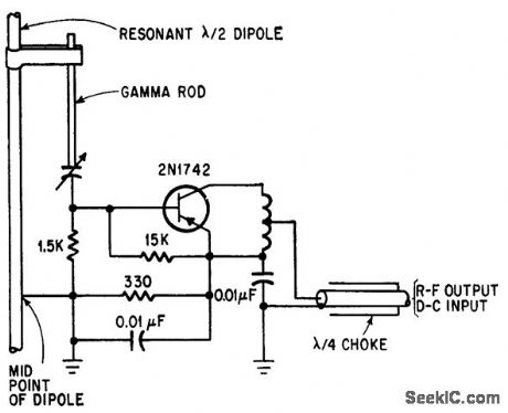
Transistorized dipole antennafier operates with fixed bias for maximum gain or minimum noise temperature. Gamma rod provides matching so transistor sees pure resistance.-J. F. Rippin, Making the Antenna an Active Partner, Electronics, 38:16, p 93-96. (View)
View full Circuit Diagram | Comments | Reading(772)
Long_life_battery_powered_light_detector_alarm
Published:2009/7/19 22:38:00 Author:Jessie
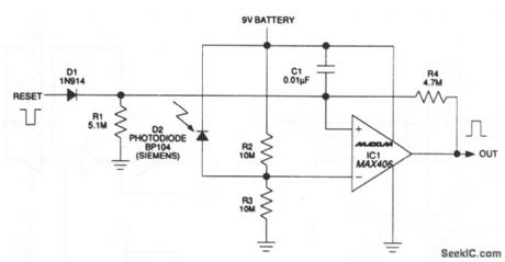
This circuit draws only 1.5μA. At this load, a 9-V alkaline battery can supply 200 mA/hours, which translates to a 15-year life (the shelf life of the battery will most likely end sooner). The circuit output latches high when light is detected. If the sensor is exposed, the output remains on until it is reset. The MAX406 operates as a comparator and as a latch by adding hysteresis externally via R4. Maxim 1992, Applications and Product Highlights, p 5-8 (View)
View full Circuit Diagram | Comments | Reading(957)
8085_CPU_to_RS_232C_interface_using_an_MC1488_and_an_MC1489
Published:2009/7/19 22:38:00 Author:Jessie

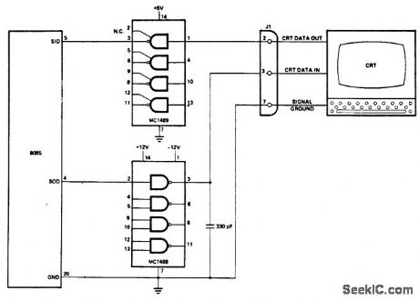
8085 CPU to RS-232C interface using an MC1488 and an MC1489 (courtesy Intel Corporation). (View)
View full Circuit Diagram | Comments | Reading(1852)
FOUR_TRANSISTOR_TRF
Published:2009/7/19 22:37:00 Author:Jessie
Single-channel receiver fits into one temple piece of eyeglass frame, with ferrite antenna in other piece, and separate miniature earphone.-H. F. Cooke, Transistor Eyeglass Radio, Electronics, 32:39, p 88. (View)
View full Circuit Diagram | Comments | Reading(905)
POWER_CONSUMPTION_LIMITER
Published:2009/7/10 2:04:00 Author:May
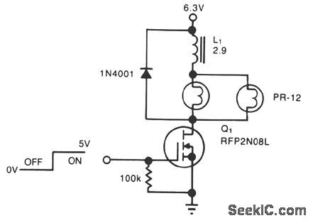


A simple solenoid driver uses incandescent lamp filaments as on-indicators to limit power con-sumption. High magnetic reluctance (opposition to flux) in the coil of an armature-driven device, such as a solenoid or relay, calls for a surge of activation current, followed by a lower dc level to remain on,since surge to on-current ratio is typically 5:1. The cold filament allows a surge of coil-activation current to pass through; as the filament heats up, it throttles the current to a more reasonable hold value. The solenoid driver circuit offers these features: ●5-V logic swings turn the power-MOSFET switch, Q1, fully on and off. ●Two low-cost flashlight lamps, in parallel, handle the peak current. Because their dc current is only 50% of peak and because they operate at 60% of their rated voltage, the lamps have an operating life of 12,000 hours. Further, the lamp filaments' positive temperature coefficients raise each filament's resistance. This rise in resistance liminates current-hogging problems and provides short-circuit protection.●The steady-state on-current is 700 mA, vs. 1700 mA without the lamps.
●A 4.6-V min supply rating allows battery opera-tion. (View)
View full Circuit Diagram | Comments | Reading(827)
CURRENT_FOLDBACK_PROTECTION
Published:2009/7/19 22:37:00 Author:Jessie
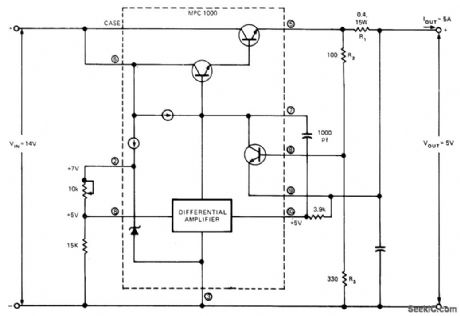
MPC1000 hybrid regulator provides regulated output of 5 V at 5 A from 14-V input. Values of components are based on foldback current of 6 A and short-circuit current of 2 A; this ensures that dissipation of regulator on short-circuit is Iess than dissipation at rated Ioad. Short-circuit current is controlled by diode drop across Ra and foldback current by drop across R2 Article gives design equations and procedure for obtaining other output voltages. Circuit also serves to limit starting surges into capacitive load, and reduces heatsink size and transistor ratings. ReturningR3 to pin 2 of MPC1000 instead of pin 3 gives lower short-circuit current, improves ef-ficiency, and reduces heat generation. Foldback protection is not suitable for variable-output supplies because foldback current is propor-tional to output voltage.-R. L. Haver, Use Cur-rent Foldback to Protect Your Voltage Regula-tor, EDNMagazine, Aug. 20, 1974, p 69-72. (View)
View full Circuit Diagram | Comments | Reading(1378)
| Pages:846/2234 At 20841842843844845846847848849850851852853854855856857858859860Under 20 |
Circuit Categories
power supply circuit
Amplifier Circuit
Basic Circuit
LED and Light Circuit
Sensor Circuit
Signal Processing
Electrical Equipment Circuit
Control Circuit
Remote Control Circuit
A/D-D/A Converter Circuit
Audio Circuit
Measuring and Test Circuit
Communication Circuit
Computer-Related Circuit
555 Circuit
Automotive Circuit
Repairing Circuit