
Control Circuit
Index 79
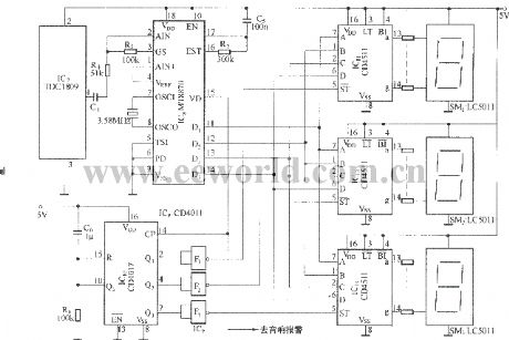
Infrared detection multiple-channel wireless alarm circuit TDC1808/TDC1809
Published:2011/9/4 22:34:00 Author:TaoXi | Keyword: Infrared, detection, multiple-channel, wireless, alarm circuit
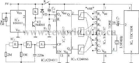
Launch circuit:
Receiving circuit:
(View)
View full Circuit Diagram | Comments | Reading(1055)
Temperature window overrun alarm circuit MAX6502/4
Published:2011/9/4 21:18:00 Author:TaoXi | Keyword: Temperature window, overrun, alarm circuit
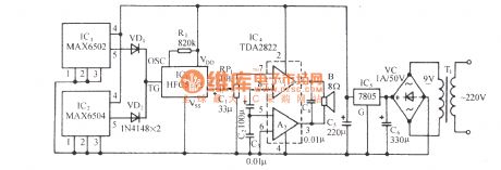
The circuit is as shown in the figure, it is composed of the upper limit and lower limit temperature detection circuit, the voice circuit, the audio amplifier circuit and the AC step-down rectifier circuit. The temperature upper limit monitor uses the temperature switching integrated circuit MAX6502 to monitor, it can changes the temperature of the monitored objects into the corresponding electric signals, when the signal voltage exceeds the threshold temperature, the voltage comparator of the switch compares and adjudges the signal, and the monostable trigger outputs the plastic pulse, the push-pull output level outputs the high level control signal.
(View)
View full Circuit Diagram | Comments | Reading(788)
Cultural relics museum metal detection volice alarm circuit
Published:2011/9/4 21:09:00 Author:TaoXi | Keyword: Cultural relics museum, metal detection, volice alarm
Some memorial halls, museums and treasure exhibition halls always have the unpleasant inspection to prevent the metal objects of the visitors. This circuit is installed at the entrance of the hall, it can detect the metal objects automatically and send out the voice of Please do not bring the metal products inside . This circuit is as shown in the figure.
(View)
View full Circuit Diagram | Comments | Reading(1647)
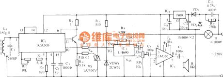
The piezoelectric type high material level automatic control and alarm circuit
Published:2011/9/4 21:01:00 Author:TaoXi | Keyword: piezoelectric type, high material level, automatic control, alarm circuit

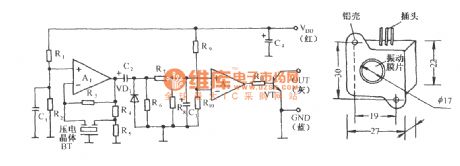
As the figure shows, it is composed of the piezoelectric type material level, the relay control mechanical circuit, the analog sound circuit and the AC step-down rectifier circuit. When the material level rises to the high level, the circuit can send out the analog sound and cuts off the power supply of the material feeding equipment, so the material feeding stops to ensure the safety. IC1 is the piezoelectric type material level sensing integrated circuit, it is composed of the self-excited oscillator, the rectifier circuit, the voltage comparator circuit and the open-circuit output level, the internal circuit is as shown in the figure.
(View)
View full Circuit Diagram | Comments | Reading(783)
Flow speed indicator circuit
Published:2011/8/26 3:12:00 Author:Jessie | Keyword: Flow speed, indicator
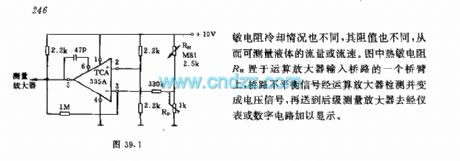
This circuit uses thermistors for load to measure flow. For a certain liquid medium, when its velocity is not the same, thermistors' cooling conditions are different neither, so itcan measure the liquid flow quantityor flow rate. In diagram, thermistors RH is put on the the arm of amplifier input bridge road, Bridge road unbalanced signal is detected by amplifierand become voltages, then it issent to the latter stage measurement amplifier or digital circuit to display.
(View)
View full Circuit Diagram | Comments | Reading(833)
Delayed releasing relay
Published:2011/8/29 1:39:00 Author:Jessie | Keyword: Delayed releasing relay
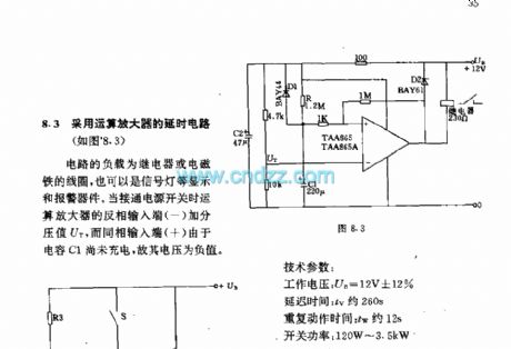
Circuit's load is relay or electromagnet coils of wire,and it alsocan be usedas the signal lightdisplay and alarm device etc. When it turns on the power switch, the input bonus of inverse's operational amplifieris added toUT, while in-phase input capacitor C has not been charged, so voltage is negative.
Technical parameters: Working voltage: UB = 12V ± 12% delay time: tV is about 260S Repeat Time: tw is about 12s switch power: 120w ~ 3.5kW.
(View)
View full Circuit Diagram | Comments | Reading(754)
Superposition has pulse delay suck close relay circuit
Published:2011/8/29 1:47:00 Author:Jessie | Keyword: Superposition has pulse, delay suck close, relay
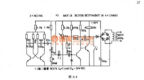
After the switchgets power, time process begins, capacitor C isdischarged firstlyand then charged by20MΩ charging resistor. The capacitor's recharging voltage has a negative pulse. This pulse isproduced by astable multivibrator's transistorsBC170C with differential capacitor and goten from 1.8 Ω resistor. Sharp pulse's value is about 4.5 V, interval is 20ms, and time constantis 50 μs.
(View)
View full Circuit Diagram | Comments | Reading(784)
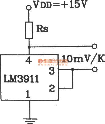
Single power supply temperature measurement circuit composed of LM3911 monolithic temperature control IC
Published:2011/8/22 3:29:00 Author:Jessie | Keyword: Single power supply, temperature measurement circuit, monolithic temperature control IC
View full Circuit Diagram | Comments | Reading(1089)
A humidity/frequency-audio decoding humidity detection, automatic exhaust ventilation croak sound circuit
Published:2011/8/26 2:05:00 Author:Jessie | Keyword: humidity/frequency, audio decoding humidity detection, automatic exhaust ventilation
The circuit is shown as the chart, it is composedof wet sensors, time-based oscillator, audio decoder, SCR control exhaust fan circuit, croak sound circuit and AC step-down rectifier circuit, etc. Only when environment humidity reaches a set humidity value, audio decoderwill output signal of control fan start toundertake ventilated dehumidification, it also emits several croak sound to remind consumer's attention.
(View)
View full Circuit Diagram | Comments | Reading(1348)
Liquid surface and temperature control circuit
Published:2011/8/26 3:30:00 Author:Jessie | Keyword: liquid surface, temperature control
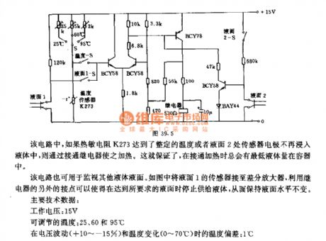
In this circuit, if thermistor K273 reaches the setting temperature or liquid level 2's sensor no longer dipped into the liquid, then heat it by connecting the relay. It ensures there will be minimum liquid in a containerwhen heated. This circuit can also be used in spying on other liquid surface.It connectsliquid surface 1's sensor to a differential amplifier, and uses another relay contact to stop supplyingliquid when it has reached the required liquid surface, then it can remain the liquid surface. (View)
View full Circuit Diagram | Comments | Reading(730)
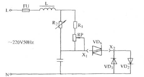
Piezoresistor protection transistor circuit
Published:2011/8/26 3:29:00 Author:Jessie | Keyword: piezoresistor, protection transistor
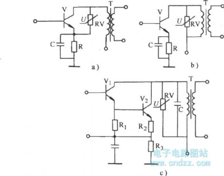
As shown in Figure a, it uses non-linear relationship of the piezoresistor to achieve the protectionfor the transistor. In Figure b, c, due to induced over-voltage suppression is below the specified value, C ~ E poles will not exceed the specified threshold voltage,so itcan play a protective role of the transistor.
(View)
View full Circuit Diagram | Comments | Reading(863)
Current limiting protection circuit
Published:2011/8/26 3:26:00 Author:Jessie | Keyword: current limiting protection
View full Circuit Diagram | Comments | Reading(962)
Two-way diode quality judgement circuit
Published:2011/8/26 3:37:00 Author:Jessie | Keyword: two-way diode, quality judgement
View full Circuit Diagram | Comments | Reading(812)
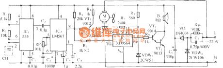
Aquarium automatic temperature constant circuit
Published:2011/8/26 3:07:00 Author:Jessie | Keyword: aquarium, temperature constant
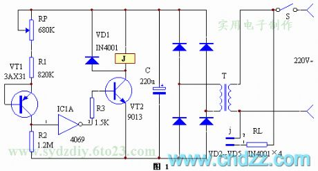
When the temperature of water below the set temperature (tropical fish is usually 23-27℃), 3AX31's Iceo is lower, its resistance increases,a isthe low level, it will output high potential after IC1A reversed-phase, VT2 connected, relay j1 suck close, hot converter R4 works. Conversely, a is the high level, VT2 stops, j1 releases, R4 blackouts.
Thermal componentsshould choosegermanium transistors 3AX31, 3AX34 with better temperature curve.The inverter chooses CD4049 or CD4069. Power transformeruses 10V ,2-5W small transformers.
The tank thermostat is suitable for tropical fish breeding feeding enthusiasts, andthe circuit issimple and effective.
(View)
View full Circuit Diagram | Comments | Reading(1524)
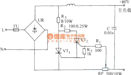
Send current protection circuit with thermistors
Published:2011/8/26 3:01:00 Author:Jessie | Keyword: Send current protection, thermistors
The circuit can be usedto prevent the liquid in containeroverflow. T1 is constant current source, R2 is thermistor and sensor which is used to heat. The media types and temperature regulation ofthe place of sensor could make current flowthrough sensor and produce heat whichis equal to the heat from surrounding media emissions. Now assuming R2 is in air, so emissionsheat is small, R2 temperature will increase to the highest, R2 resistance is low. As a result, A's potentialis high, T2 and T5 are connected, so is the relay. If R2 dip in fluid-filled containers, then R2's temperature drop, its resistance increases, A's potentialis low, T2 and T5 are disconnected,neither is the relay. Thus, it can be used to detect liquid face whether has overflow.
(View)
View full Circuit Diagram | Comments | Reading(745)
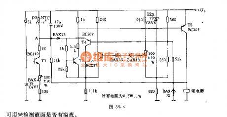
Liquid surface safety alarm circuit with thermistors
Published:2011/8/26 2:10:00 Author:Jessie | Keyword: safety alarm, thermistors
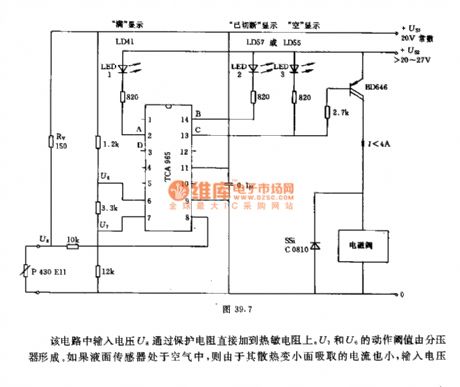
This circuit inputs voltage U8 is added to thermistorsthrough protection resistor . U7 and U6's action thresholdsare formedby bleeder. If liquid surface sensor isin air, its cooling decrescent surface absorbs little, input voltage U8 increses, but it is lower than threshold of U6. So integrated circuit output terminal C is connected, send out empty signal. At the same time, it flows thorugh the Dalindun transistor BD646 which makes the filling valve open. When thermistors liquid surface sensor dipped into the liquid, drain current increases, Rv's voltage drop increases, U8's voltage ris educed to U7's threshold, output A connects lamp L1, and it will show box full signal. When sensor isin short circuit, it will produce above-mentioned switch positions. But when sensor is disconnected, input voltage U8 increases to power voltage, higher than threshold. (View)
View full Circuit Diagram | Comments | Reading(1237)
HD-3A Energy-saving quota three-phase power supply protector
Published:2011/8/26 3:36:00 Author:Jessie | Keyword: Energy-saving, three-phase power supply
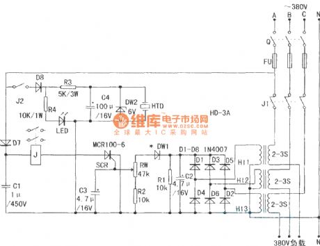
Current transformer H11-3 needs to be made by yourself. It can choose transformer core which is not less than 2W, and the secondary should be wound firstly. It uses Φ0.12mm enameled wire with around 1000 turns. Primary uses Φ1 ~ 4mm plastic wire with around 2-3 turns. It also can use finished CT. Finished current transformer has high induced voltage.
(View)
View full Circuit Diagram | Comments | Reading(1313)
The power grid voltage fault protection indication circuit
Published:2011/8/29 2:18:00 Author:Jessie | Keyword: power grid, voltage fault protection, indication circuit
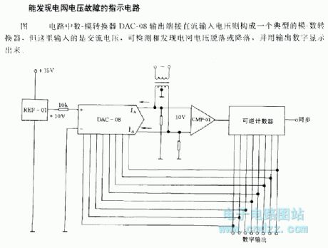
The analog- digital converter DAC-08 output terminal in circuit shown as the chart is connected DC input voltage to constitute typical analog - digital converter, but here is the AC input voltage, and it can detect and find grid voltage falling off or landing, and display it with digit. (View)
View full Circuit Diagram | Comments | Reading(835)
Over voltage, over current protection circuit
Published:2011/8/26 3:32:00 Author:Jessie | Keyword: over voltage, over current, protection

During normal working, Tr1 and Tr2 are both disconnected, 555 resets, the discharge transistor in 555 is connected, it drains current from the base of Tr3, so that Tr3 is saturated, power 5 to 12V is directly sent to lord load. When load current exceeds prescribed value, Rsc's pressure drop increases, Tr1 is connected, 555 istriggered, internal discharge transistor stop, then Tr1 disconnected too, isolate the source and load, then 555 is monostable, reach single firm time, as long as the load flow phenomena is not ruled out, 555 will trigge again, Tr3 will still isolate load.
(View)
View full Circuit Diagram | Comments | Reading(2173)
Over current protection circuit
Published:2011/8/26 3:30:00 Author:Jessie | Keyword: over current protection
View full Circuit Diagram | Comments | Reading(3508)
| Pages:79/312 At 206162636465666768697071727374757677787980Under 20 |
Circuit Categories
power supply circuit
Amplifier Circuit
Basic Circuit
LED and Light Circuit
Sensor Circuit
Signal Processing
Electrical Equipment Circuit
Control Circuit
Remote Control Circuit
A/D-D/A Converter Circuit
Audio Circuit
Measuring and Test Circuit
Communication Circuit
Computer-Related Circuit
555 Circuit
Automotive Circuit
Repairing Circuit