
Control Circuit
Index 69
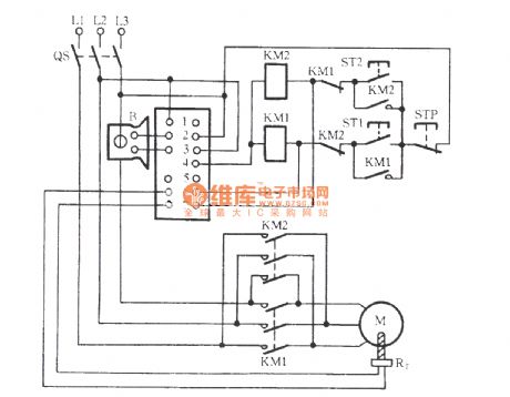
QM9403 three-phase motor protection circuit
Published:2011/12/7 2:04:00 Author:Ecco | Keyword: three-phase, motor protection circuit
View full Circuit Diagram | Comments | Reading(2462)
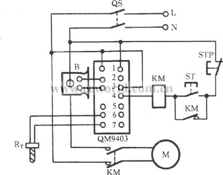
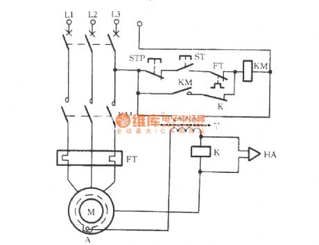
QM9403 single-phase motor protection circuit
Published:2011/12/7 1:49:00 Author:Ecco | Keyword: single-phase , motor protection
View full Circuit Diagram | Comments | Reading(2178)
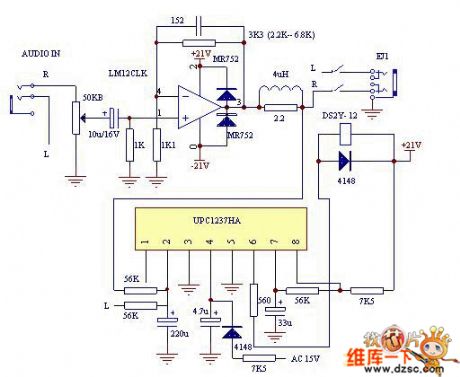
UPC1237 speaker protection circuit ( LM12 power amp circuit )
Published:2011/12/9 0:57:00 Author:Ecco | Keyword: speaker, protection circuit , power amp
View full Circuit Diagram | Comments | Reading(28193)
M7120A surface grinding machine control circuit
Published:2011/12/7 1:59:00 Author:Ecco | Keyword: surface grinding machine, control circuit
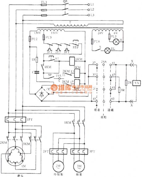
M7120A surface grinding machineconsists ofthe bed , table , electromagnetic chuck , grinding , slide , column , etc., andthe control circuit is shown as the chart.
(View)
View full Circuit Diagram | Comments | Reading(4434)
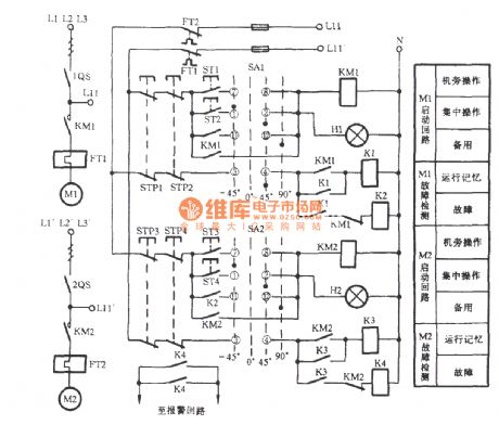
Automatic input control circuit of the spare motor
Published:2011/12/7 1:40:00 Author:Ecco | Keyword: Automatic linput control lspare motor
View full Circuit Diagram | Comments | Reading(677)
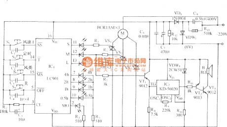
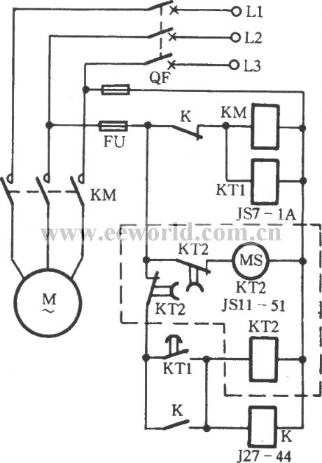
Multi-function fan with frogs calling control circuit using LC903
Published:2011/12/7 1:37:00 Author:Ecco | Keyword: Multi-function fan , frogs calling , control circuit
View full Circuit Diagram | Comments | Reading(719)
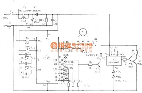
The multi-function fan with frogs calling control circuit using LC901
Published:2011/12/6 21:22:00 Author:Ecco | Keyword: multi-function fan , frogs calling , control circuit
View full Circuit Diagram | Comments | Reading(753)
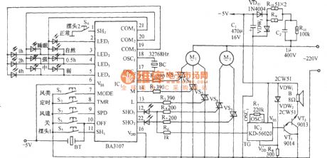
Multi-function fan with animal sound control circuit using BA3107
Published:2011/12/6 21:45:00 Author:Ecco | Keyword: Multi-function fan , animal sound , control circuit
View full Circuit Diagram | Comments | Reading(913)
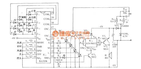
Multi-function fan with nature sound control circuit using BA3106
Published:2011/12/6 21:44:00 Author:Ecco | Keyword: Multi-function fan , nature sound , control circuit
View full Circuit Diagram | Comments | Reading(755)
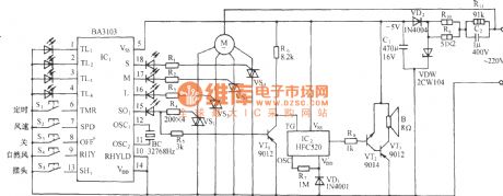
Multi-function fan with seashore control circuit using BA3103
Published:2011/12/6 21:43:00 Author:Ecco | Keyword: Multi-function fan , seashore , control circuit
View full Circuit Diagram | Comments | Reading(760)
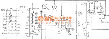
Multi-function fan with twitter control circuit using BA3102
Published:2011/12/6 21:42:00 Author:Ecco | Keyword: Multi-function fan , twitter , control circuit
View full Circuit Diagram | Comments | Reading(798)
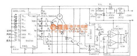
Multi-function fan control circuit using BA3101
Published:2011/12/6 21:40:00 Author:Ecco | Keyword: Multi-function fan , control circuit
View full Circuit Diagram | Comments | Reading(809)
Automatic intermittent lubrication control circuit
Published:2011/12/6 1:47:00 Author:Ecco | Keyword: Automatic, intermittent lubrication , control circuit
View full Circuit Diagram | Comments | Reading(754)
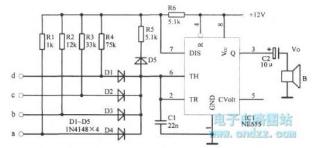
Multi-tone alarm
Published:2011/11/11 2:56:00 Author:Ecco | Keyword: Multi-tone alarm
View full Circuit Diagram | Comments | Reading(1116)
Timing control circuit diagram
Published:2011/10/18 21:25:00 Author:Ecco | Keyword: Timing control
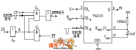
The timing control circuit is key to the design for responder, it should complete the following three functions: ① The host pulls the controlling switch to start position, then the speaker emits sound, the answer circuit and timing circuit will be in normal working condition. ② When the players press the answer key, speaker works, then the answer circuit and timing circuit stop working. ③ When the set answer time is up, no answer in time, the speaker also emits sound, then the answer circuit and timing circuit stop working.
(View)
View full Circuit Diagram | Comments | Reading(993)
Electric flute alarm circuit
Published:2011/11/8 21:10:00 Author:Ecco | Keyword: Electric flute alarm, 555
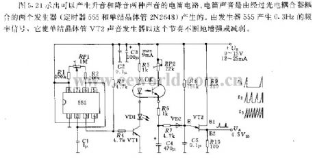
Figure 5.21 shows the tone circuit circuit which can produce two voices with rising tone and dropping tone. Electric flute sound is generated by two generators coupled by optical coupler ( single-junction transistor 2N2648 and the timer 555). 555 generates 0.3HZ frequency signal which makes single-junction transistor VT2 keep this sound increasing or decreasing according to the section.
(View)
View full Circuit Diagram | Comments | Reading(1558)
Motor immersion protection circuit
Published:2011/11/8 21:11:00 Author:Ecco | Keyword: Motor immersion protection
View full Circuit Diagram | Comments | Reading(1210)
The 8019 schematic diagram controlling by 5402
Published:2011/11/8 21:13:00 Author:Ecco | Keyword: schematic diagram
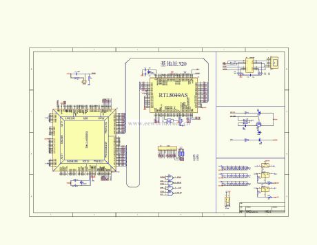
View full Circuit Diagram | Comments | Reading(883)
Automatic telephone recording controlling device
Published:2011/11/8 20:33:00 Author:Ecco | Keyword: Automatic, telephone recording , controlling device
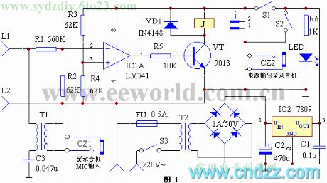
View full Circuit Diagram | Comments | Reading(924)
Motor overload protection circuit
Published:2011/11/8 20:32:00 Author:Ecco | Keyword: Motor overload protection
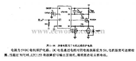
The circuit is the 5VDC motor protection circuit. The current extreme of DC current passing the motor is 5A, and the motor temperature is monitoring continuously, when it is more than 70 ℃, LTC1153 has fault signal sending to the computer, then the computer automatically shut off the machine.
(View)
View full Circuit Diagram | Comments | Reading(1787)
| Pages:69/312 At 206162636465666768697071727374757677787980Under 20 |
Circuit Categories
power supply circuit
Amplifier Circuit
Basic Circuit
LED and Light Circuit
Sensor Circuit
Signal Processing
Electrical Equipment Circuit
Control Circuit
Remote Control Circuit
A/D-D/A Converter Circuit
Audio Circuit
Measuring and Test Circuit
Communication Circuit
Computer-Related Circuit
555 Circuit
Automotive Circuit
Repairing Circuit